JUMO CTI-750 Operating Manual
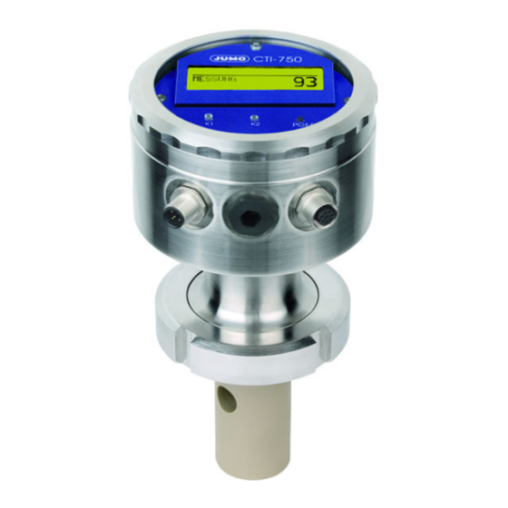
Inductive conductivity transmitter in stainless steel housing
Hide thumbs
Also See for JUMO CTI-750:
- Operating instructions manual (68 pages) ,
- Operating instructions manual (88 pages) ,
- Operating manual (88 pages)

Related Manuals for JUMO JUMO CTI-750


Summary of Contents for JUMO JUMO CTI-750
- Page 1 Inductive conductivity transmitter in stainless steel housing JUMO CTI-750 Type 202756 B 20.2756.0.1 Operating manual 11.07/00488788...
-
Page 3: Table Of Contents
Function .....................12 Identifying the device ............. 13 Type nameplate ..................13 Type declaration ..................14 JUMO CTI-750 as "Head transmitter" ............14 JUMO CTI-750 as "Transmitter with separate sensor" ......15 Device description ..............17 Technical data, transmitter ..............17 Assembly .................. 21 General ...................... 21 Dimensions / Process connections, head transmitter .......22... - Page 4 Contents Operation ................. 36 10.1 Operating elements ..................36 10.2 Principle of operation .................38 10.3 Principle .....................40 10.4 Measurement mode ...................41 10.5 Operator level .....................41 10.6 Administrator level ..................49 10.7 Calibration level ..................51 10.8 The desalination function ................52 Calibrating ................56 11.1 General ......................
- Page 5 A/D-converter Sediments CIP-Process Desalination reduction DESALINATION FUNCTION Desalination function DOSING TIME Desalination function: Start Dosing time Desalination function: Stop Pressure Desalination Desalination valve REDUCTION Levels of the Administrator level Reduction MOUNTING FACTOR DISTANCE Mounting factor Distance Installation position Alarm window Installation variants –...
- Page 6 – Manual operation MANUAL VALUE Parameters, configurable – Manual value Password Date of manufacture Polarization Attention-drawing signs PULSE DURATION Hold function Pulse duration HYSTERESIS Reference fluid CALIBR.-INTERVAL Reference measuring instrument Calibration interval Reference temperature Calibration timer REL. CELL CONSTANT Characteristic Relative cell constant Compensation range Configurable parameters...
- Page 7 LOCKING TIME Locking time Pre-calculated values Warning signs Resistant loop Wiping contact CELL CONSTANT Cell constant permissible storage temperature permissible ambient temperature...
-
Page 8: Typographical Conventions
1 Typographical conventions Warning signs Caution This sign is used if, by carefully following or not following instructions, harm to persons can occur Caution This sign is used if, by carefully following or not following instructions, dam- age to devices or data can occur Indicative signs Note This sign is used when your attention is to be drawn to something special. -
Page 9: General
Please get in touch with the nearest branch or with the head office. In case of technical queries Service-Hotline: Telephone:(06 61) 60 03-3 00 or (06 61) 60 03-6 53 Telefax: (06 61) 60 03-88 13 00 or (06 61) 60 03-88 16 53 E-mail: Service@jumo.net... -
Page 10: Structure Of The Jumo Cti-750
2 General Structure of the JUMO CTI-750 Examples Model: Model: Transmitter and Transmitter with conductivity measuring separate sensor, probe combined, type 202756/xx... type 202756/xx... (1) Transmitter (4) Inductive conductivity measuring probe (2) Process connection (5) with or without graphics LC-display... -
Page 11: Inductive Conductivity Measurement
/ display. In this case, the Setup program is required for programming. The JUMO CTI-750 can be supplied as a combine device (transmitter and measuring cell in one device) or as a shouldered version (transmitter and mea- suring cell connected by cables). -
Page 12: Function
3 Inductive conductivity measurement Function of the transmit- The JUMO CTI-750 transmitter is conceived for use at the location. A robust housing protects the electronics and the electrical connections from aggres- sive ambient influences (system of protection IP 67). In the standard version, the device has one analog signal input for the conductivity / concentration and the temperature. -
Page 13: Identifying The Device
4 Identifying the device Type nameplate on the transmitter JUMO GmbH & Co. KG Fulda, Germany www.jumo.net JUMO CTI-750 Typ: 202756/16-607-0000-82/000 VARTN: 20/00445843 F-Nr.: 00909467 01 0 0745 0001 DC 19...31 V on the connect- cable (only in case of F-Nr.: 00909467 01 0 0517 0001... -
Page 14: Type Declaration
4 Identifying the device Type explanation JUMO CTI-750 as "Head-mounted transmitter" (1) Basic type 202756 JUMO CTI-750 Inductive transmitter / switching device for conductivity / concentration and temperature (2) Basic type supplementation Head-mounted transmitter in stainless steel housing with display / keyboard... -
Page 15: Jumo Cti-750 As "Transmitter With Separate Sensor
4 Identifying the device JUMO CTI-750 as "Transmitter with separate sensor" (1) Basic type 202756 JUMO CTI-750 Inductive transmitter / switching device for conductivity / concentration and temperature (2) Basic type supplementation Transmitter in stainless steel housing, with display / keyboard... - Page 16 4 Identifying the device Ordering key Ordering example 202756 / 66 - 607 - 1000 - 82 / 767 Assembly material (Union / grooved nut, mounting bracket) not part of scope of supply. If required, please order as well, see accessories. Only in conjunction with additional code 767 (measuring cell material PEEK).
-
Page 17: Device Description
5 Device description Technical data, transmitter 5.1.1 General A/D-converter Resolution: 15-bit sampling time:500 ms = 2 measurements/s Voltage supply For operation on SELF- or PELV-circuits Standard production feature: DC 19…31 V (nominal DC 24 V), the device has reverse polarity protection Ripple: <... -
Page 18: Output Signal
5 Device description 5.1.2 Conductivity-/ Concentration transmitter Concentration - NaOH (sodium hydroxide solution) measurement 0...15 % by weight or 25...50 % by weight (implemented in - HNO (nitric acid); pay attention to the chemical resistance of the sensor! the device soft- 0...25 % by weight or 36...82 .% by weight ware) - Customer-specific concentration curve... -
Page 19: Output Signal, Temperature
5 Device description not temperature-compensated Note: The overall accuracy is formed from the accuracy of the transmitter + the accuracy of the sensor. 5.1.3 Temperature transmitter Temperature manual -20.0...25.0...150°C / °F acquisition automatic Temperature -20...150°C / °F measurement range Characteristic linear ≤... -
Page 20: Pressure
5 Device description Compensation -20...150°C range Function - Linear compensation (constant temperature coefficient). This type of compensation can be applied with acceptable for many normal types of water. The temperature coefficient used is then about 2.2 %/K. - Natural water (DIN EN27888 or ISO 7888). In this case, a so-called non-linear temperature compensation is applied. -
Page 21: Assembly
In immersion operation in a basin, an installation location that is representative for the typical conductivity or concentration must be provided. Mounting loca- The JUMO CTI-750 can be mounted in any position. tion Screwing in and No cable twisting should occur. -
Page 22: Dimensions / Process Connections, Head Transmitter
6 Installation Dimensions / Process connections, head transmitter Installation vari- ants Process connection Slotted union nut (1.4301) Model with process connection Model with process connection 607 107 = Stud thread G1 1/4A MK DN50 108 = Stud thread G1 1/2A 110 = Stud thread G2A Process Process... - Page 23 6 Installation Process connection (1.4301) Ring nut SMS 2" (1.4301) Model with process connection 690 SMS 2"...
-
Page 24: Jumo Cti-750 With Separate Sensor
6 Installation JUMO CTI-750 with separate sensor Transmitter- head ø110 Wall fastening... - Page 25 6 Installation Sensor part M12 socket M12 socket (PBT / PA) (PBT / PA) Cable gland Cable gland M16 (PA) M16 (PA) Process connection (1.4301) Shouldered version with Shouldered version with process connection 607 process connection MK DN50 107 = Stud thread G1 1/4A (union nut not part 108 = Stud thread G1 1/2A of scope of supply)
- Page 26 6 Installation M12 socket (PBT / PA) Cable gland M16 (PA) Process connection (1.4301) Shouldered version with process connection 690 SMS 2" (union nut not part of scope of supply)
- Page 27 6 Installation 6.3.1 Separate sensor as submerged version M12 socket (PBT/PA) Fixing screw Flange mova ø 18 ø 100 ø 165 Cable gland System of protection IP68 up to 0,2 bar) Optional accessories: according to EN 60529 Flange DN 32, Sales no.: 20/00083375 (PA) Submerged pipe...
-
Page 28: Assembly Examples
Ring nut DN50 (1.4301) Reducing Tee DIN, short SSS DN65/50 (e.g. 1.4301) (to be provided by the plant operator supplied by JUMO) Process sonnection 607 Screwed pipe fitting DN50 DIN11 851 (MK DN50, Milk cone) Tee DIN 11 852, SSS (1.4301) - Page 29 6 Installation Tee DIN, short SSS DN65/50 (e.g. 1.4301) (to be provided by the plant operator supplied by JUMO)
-
Page 30: Installation
7 Installation The electrical connections may only be set up by technically qualified personnel. When selecting the conductor material for the installation and for the elec- trical connections of the device, compliance is required with the specifica- tions of VDE 0100 "Regulations governing the installation of heavy-current systems with rated voltages below 1000 V"... -
Page 31: General
7 Installation General Open the oper- ating unit Unscrew the cover (1) Connect the cables SETUP For connecting the individual cores, pull out the threaded plug terminals (1) in the operating unit. Lead the connecting cables through the cable glands (2). -
Page 32: Removing The Pigmenting
7 Installation Wiring In the case of devices with a separate sensor (base type supplementation (2) /65 or /60), for every instrument, the transmitter and the separate sensor are matched to one another at the factory. When connecting the components, ensure that the production number of the external sensor (on the flag tag on the connecting cable) is identical to the pro- duction number of the transmitter (on the nameplate). -
Page 33: Outputs
7 Installation Connection lay- Connection Threaded Plug / Pin out of the trans- terminals mitter Voltage supply Standard production feature: 1 L+ I / 1 Voltage supply 2 L- I / 2 DC 19…31 V (with polarity reversal protection) In case of extra code 844: AC 24 V Outputs analog signal output... -
Page 34: Setup Program
8 Setup-Program Function Configurable With the optional Setup program that is available, the transmitter can be com- parameters fortably matched to the requirements. - Setting the measurement range and the measurement range limits. - Setting the behavior of the outputs in case of overshooting of the measure- ment range. -
Page 35: Commissioning
9 Commissioning The measuring transmitters are checked in the factory for flawless operability and shipped ready for operation. Head transmitter or transmitter with separate sensor Install the device, see "Installation", page 21. Connect the device, see "Installation", page 30. In the case of devices with a separate sensor (base type supplementation (2) 66), for every instrument, the transmitter and the separate sensor are matched to one another at the factory. -
Page 36: Operation
10 Operation 10.1 Operating elements JUMO CTI-750 with and with- LC-Display (1) Graphical LC-display, (6) LEDs "K1" / "K2" indicate the background lit up. status of the switching outputs. In normal operation, the LED (2) Key flows when the corresponding confirm inputs, select menu. - Page 37 10 Operation LC-Display (11) (10) Output K1 is active Output mode - manual (manual operation) Output K2 is active - hold (hold operation) Binary input 1 is Conductivity /concentration- triggered measured value Binary input 2 is Unit of the conductivity- /con- triggered centrations measured value Keyboard is locked...
-
Page 38: Principle Of Operation
10 Operation 10.2 Operation principle 10.2.1 Operating in levels Measurement mode, see chapter 10.4 "Measurement mode", page 41 OPERATOR LEVEL, see chapter 10.5 "Operating level", page 41 INPUT CONDUCTIVITY MEASUREMENT RANGE 1...4 TEMP.COMPENSATION TEMP.COEFFICIENT 1...4 REFERENCE TEMPERATURE REL.CELL CONSTANT MOUNTING FACTOR CONCENTR.MEASUREMENT CONCENTR.RANGE OFFSET... - Page 39 10 Operation DEVICE DATA LANGUAGE CONTRAST LIGHTING LCD INVERSE ADMINISTR.-LEVEL, see chapter 10.6 "Administrator level", page 49 Password PARAMETER-LEVEL, see chapter 10.6.1 "Parameter level", page 50 INPUT CONDUCTIVITY. OUTPUT CONDUCTIVITY INPUT TEMPERATURE OUTPUT TEMPERATURE OUTPUT BINARY 1 OUTPUT BINARY 2 INPUT BINARY 1 INPUT BINARY 2 DESALINATION FUNCTION...
-
Page 40: Principle
10 Operation 10.3 Principle Level... -
Page 41: Measurement Mode
10 Operation 10.4 Measurement mode Depiction In the measurement mode, the conductivity compensated to the reference temperature, or the concentration, and the temperature of the measurement medium are displayed. MEASUREMENT -> Measurement mode 20.5°C -> Temperature of the measurement medium 203 mS/cm ->... -
Page 42: Input Conductivity
10 Operation 10.5.1 INPUT CONDUCTIVITY (Input conductivity) MEASUREMENT RANGE 1...4 0...500 µS/cm 0...1000 µS/cm 0...2000 µS/cm 0...5000 µS/cm 0...10 mS/cm 0...20 mS/cm 0...50 mS/cm 0...100 mS/cm 0...200 mS/cm 0...500 mS/cm 0...1000 mS/cm 0...2000 mS/cm UNK The measurement ranges 2, 3 and 4 are only used if "INPUT BINARY"... -
Page 43: Mounting Factor
10 Operation MOUNTING FACTOR 80.0...100.0...120% If the minimum distances (20 mm) of the sensor to the outer wall cannot be maintained, a limited compensation can be achieved with this parameter. CONCENTR. MEASUREMENT NO FUNCT. NaOH HNO3 CUST. SPEC. (The input of the values is only possible with the optional Setup program) CONCENTR. -
Page 44: Output Conductivity
10 Operation 10.5.2 OUTPUT CONDUCTIVITY. (Output conductivity) SIGNAL TYPE 0...20 mA 4...20 mA 20...0 mA 20...4 mA 0...10 V 2...10 V 10...0 V 10...2 V SCALING START 1...4 0 µS/cm = 4 mA Can be set in the current measurement range, depending on the signal type The ranges 2, 3 and 4 are only used if "INPUT BINARY"... -
Page 45: Unit
10 Operation 10.5.3 INFLOW TEMPERATURE UNIT °C °F MEASUREMENT VALUE ACQUISITION Sensor manual MANUAL SPECIFICATION -20.0...25.0...150.0°C OFFSET -15.0...0.0...+15.0°C FILTERING TIME 00:00:00...00:00:01...00:00:25 H:M:S 10.5.4 OUTFLOW TEMPERATURE SIGNAL TYPE 0...20 mA 4...20 mA 20...0 mA 20...4 mA 0...10 V 2...10 V 10...0 V 10...2 V SCALING START -20 ... -
Page 46: Output Binary
10 Operation AT THE TIME OF CALIBRATION ACCOMPANYING FROZEN SAFETY VALUE SAFETY VALUE 0,0...4,0...22,0 mA (depending on the signal type) 0...10,7 V MANUAL OPERATION MANUAL VALUE 0,0...4,0...22,0 mA (depending on the signal type) 0...10,7 V 10.5.5 OUTPUT BINARY 1 and OUTPUT BINARY 2 FUNCTION NO FUNCTION COND. -
Page 47: Distance
10 Operation Hysterese Hysteresis Cond. Distance Abstand Limit value Grenzwert Setpoint Sollwert Alarm window LK1 Alarm window LK2 Wiper contact Wiper contact Triggering condition longer than Triggering condition shorter than pulse duration pulse duration LIMIT VALUE -20.0... 999.0 (depending on the function, see above) HYSTERESIS 0.0...1.0...999.0 (depending on the function, see above) DISTANCE... -
Page 48: Desalination Function
10 Operation SWITCH-ON DELAY 00:00:00...01:00:00 H:M:S SWITCH-OFF DELAY 00:00:00...01:00:00 H:M:S PULSE DURATION 00:00:00...01:00:00 H:M:S (see above: "Function, wiping contact) 10.5.6 INPUT BINARY 1 and INPUT BINARY 2 FUNCTION NO FUNCTION KEYBOARD LOCK/HOLD MEASUREMENT RANGE./TEMP C. DESALINATION FUNCTION. Setting parameters binary input 1 binary input 2 Measurement range- / MB1 / Tk1... -
Page 49: Administrator Level
10 Operation 10.5.8 DEVICE DATA LANGUAGE GERMAN ENGLISH FRENCH SPANISH POLISH SWEDISH ITALIAN PORTUGUESE DUTCH RUSSIAN By inputting the password 7485 in the Administrator level, the operating language is reset to English. CONTRAST 0...6...11 LIGHTING FOR OPERATION (about 50 s after the last keystroke, the lighting gets switched off) INVERSE LCD 10.6 Administrator level... -
Page 50: Levels Of The Administrator Level
10 Operation Levels of the Administrator level 10.6.1 Parameter level In this level, the Administrator can edit any parameter of the operator level. The structure of the parameter level in the Administrator level is identical to the operator level see "Operating level", page 41 and onwards. 10.6.2 Release level In this level, the Administrator can determine which parameters the operator is permitted to modify in the operator level.. -
Page 51: Calibration Level
10.7.1 REL. CELL CONSTANT. (relative cell constant) If this function has been released by the Administrator, the operator can cali- brate the relative cell constant of the JUMO CTI-750 here; see "Calibration of the relative cell constant", page 56. 10.7.2 TEMP. COEF. LINEAR (Temperature coefficient linear) If this function has been released by the Administrator, the operator can cali- brate the JUMO CTI-750 on fluids with linear temperature coefficients;... -
Page 52: The Desalination Function
- The desalination function is only possible in the mode "Conductivity mea- the case of the surement". Not in the case of concentration measurement.. JUMO CTI-750 - If the desalination function is activated, all the parameters that are not rele- vant for this function are turned off. -
Page 53: Desalination Reduction
10 Operation - The desalination reduction can be set in the range from 1...50% below the actual limit value of binary input 1. The default setting is 10% below the limit value. 10.8.1 Setting the desalination function All the parameters are plant-dependent and must be matched to the prevalent conditions. - Page 54 10 Operation With the keys , select "DESALINATION FUNCT.". with key confirm the selection. Use the key to switch to the operator level. EXIT With the key select "DESALINATION FUNCTION". With key , confirm the selection. Set the desalination reduction with the keys in the range from 1...10...50% below the actual limit value.
- Page 55 10 Operation With the keys , select "LOCKING TIME"; with key , confirm the selection. Set the locking time with the keys in the range from 0:00:00...00:01:00...18:00:00 H:M:S. with key , confirm the setting. If there is a failure of the supply voltage during the running of the desalination function, the function is canceled.
-
Page 56: Calibrating
In case of increased demands on the accuracy, the cell constant must first be calibrated. Precondition - the JUMO CTI-750 must be supplied with power. see chapter 7 "Installation", page 30ff. - The sensor must be connected to the transmitter (in case of "shouldered"... -
Page 57: Calibration Of The Temperature Coefficient Of The Measurement Solution
Press the key. The relative cell constant calculated by the JUMO CTI-750 is displayed. Accept the relative cell constant determined -> press the key for longer than 3 seconds, or discard the value ->... - Page 58 11 Calibration Precondition - the JUMO CTI-750 must be supplied with power. see chapter 7 "Installation", page 30ff. - The sensor must be connected to the transmitter (in case of "shouldered" construction). - The transmitter is in "Measurement mode". Submerge the conductivity sensor in a sample of the measurement solu- tion.
- Page 59 During the calibration, the temperature changing speed of the measurement solution of 10 K/min in the case of JUMO CTI-750 with a free-standing tem- perature sensor or 1 K/min in the case of JUMO CTI-750 with an integrated tempera- ture sensor must not be exceeded.
-
Page 60: Determining The Tc-Curve
11.3.2 Non-linear temperature coefficient (ALPHA) General Since the temperature coefficient of some media is not constant over a larger temperature range, the JUMO CTI-750 has the facility to divide a temperature range (T to T ) into 5 sub-ranges. In each of these ranges, compensation start can be carried out with different TC values. - Page 61 Here, the temperature range from the starting to the final temperature calibration on is divided into 5 equal sections. the JUMO CTI- The temperature range must be greater than 20 Kelvin and overlap the refer- ence temperature. Example: Reference temperature 25°C, starting temperature 18°C and final...
- Page 62 - 10 K/min in case of a free-standing temperature sensor and - 01 K/min in case of an integrated temperature sensor Precondition - the JUMO CTI-750 must be supplied with power. see chapter 7 "Installation", page 30ff. - The sensor must be connected to the transmitter (in case of "shouldered"...
- Page 63 11 Calibration With the keys , input the starting temperature and confirm with key . The starting temperature must be below the reference temperature (25.0°C). With the keys , input the final temperature and confirm with the key . The final temperature must be at least 20°C above the starting temperature.
- Page 64 The next temperature to be reached is displayed flashing. During the calibration, the temperature changing speed of the measurement solution of 10 K/min in the case of JUMO CTI-750 with a free-standing tem- perature sensor or 1 K/min in the case of JUMO CTI-750 with an integrated tempera- ture sensor must not be exceeded.
-
Page 65: Maintenance
12 Maintenance 12.1 Conductivity-clean sensor Do not use any solvents. Stubborn sediments or deposits can be dissolved with dilute hydrochloric acid and removed. Comply with the safety specifications. Deposits Deposits on the sensor part can be removed with a soft brush (e.g. bottle brush). -
Page 66: Rectifying Errors And Faults
13 Rectifying errors and faults Error Problem Possible cause Measure possibilities No display of measured Voltage supply absent Check voltage supply, value check terminals signal output Measured value display Sensor not submerged in Fill up tank 000 or medium; signal output 0% Tank level too low (e.g. - Page 67 In case of display values up to 20 mS, the resistance loop must have 1 turn. In case of display values from 50 mS onwards, the resistance loop must have 3 turns. The cell constant of the JUMO CTI-750 depends on the structural shape.! The Tee measuring cell has a cell constant of 6.80 1/cm.
- Page 68 13 Rectifying errors and faults Example 1 The JUMO CTI-750 with Tee-shaped measuring cell should display 20 mS: ·6.80 1/cm Ω = 340 20·10 S/cm To get a display of 20 mS/cm, the resistance loop (with 1 turn) must have a re- sistance of 340 Ohm.
-
Page 69: Pre-Calculated Values
13 Rectifying errors and faults Pre-calculated The display value 0 is obtained when the sensor is dry and without conducting values coats, as well as when there is no resistance loop. Structural shape/ Cell constant Material: PVDF Material: PEEK Material: PEEK K = 6.80 1/cm K = 5.45 1/cm K = 6.50 1/cm... - Page 70 13 Rectifying errors and faults Carry out test Determine test resistance. Connect the JUMO CTI-750 electrically, see chapter 7 "Installation", page Select the corresponding measurement range, see chapter 10.5.1 "INPUT CONDUCTIVITY (Input conductivity)", page 42 -> MEASUREMENT RANGE 1...4 Set TC to 0%/K, see chapter 10.5.1 "INPUT CONDUCTIVITY (Input con- ductivity)", page 42 ->...
- Page 71 Carry out test Prepare the conductivity test solution in a sufficiently large container Connect the JUMO CTI-750 electrically, see chapter 7 "Installation", page Select the measurement range according to the conductivity test solution, see chapter 10.5.1 "INPUT CONDUCTIVITY (Input conductivity)", page 42 - >...
-
Page 72: Annex
14 Annex 14.1 Before configuring If many parameters of the device are to be re-configured, it is advisable to make a note of all the parameters to be changed in the following table, and to process the parameters in the given sequence. The following list shows the maximum number of modifiable parameters. -
Page 73: Unit
14 Annex Parameter Selection / Range of values New setting see page Factory setting Signal type 0...20 mA 4...20 mA 20...0 mA 20...4 mA 0...10 V 2...10 V 10...0 V 10...2 V Scaling, beginning 0...90% = 4 mA (e.g.) from the measurement range scope Scaling: End 100...10% = 20 mA (e.g.) from measurement range scope... -
Page 74: Distance
14 Annex Parameter Selection / Range of values New setting see page Factory setting Scaling: End -3...150...200°C = 20 mA (100...10% of measurement range scope) In case of an alarm high safety value At the time of calibration accompanying frozen safety value Safety value 0.0...4.0...22.0 mA... -
Page 75: Lighting
14 Annex Parameter Selection / Range of values New setting see page Factory setting Function no function Keyboard locking/ Hold Measurement range / Temperature coefficient desalination function Desalination function Reduction 0...10...50% Dosing time 00:00:00...00:01:00...18:00:00 H:M:S Locking time 00:00:00...00:01:00...18:00:00 H:M:S Device data Language German English... - Page 76 JUMO GmbH & Co. KG JUMO Instrument Co. Ltd. JUMO Process Control, Inc. Street address: JUMO House 8 Technology Boulevard Moltkestraße 13 - 31 Temple Bank, Riverway Canastota, NY 13032, USA 36039 Fulda, Germany Harlow, Essex CM20 2TT, UK Phone:...
Need help?
Do you have a question about the JUMO CTI-750 and is the answer not in the manual?
Questions and answers