JUMO CTI-500 Calibration Instructions Manual
Inductive conductivity transmitter replacement sensor
Hide thumbs
Also See for CTI-500:
- Operating instructions manual (72 pages) ,
- Operating instructions manual (72 pages)
Advertisement
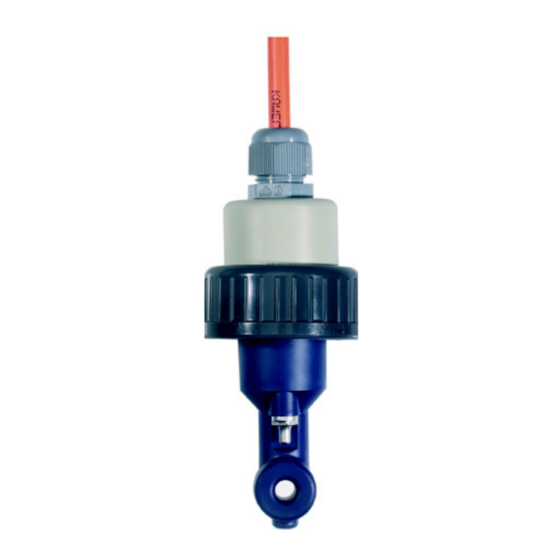
CTI-500
Replacement Sensor for
inductive conductivity/
concentration and
temperature transmitters
with switch contacts
Type 202755
B 20.2755.0.1
Calibration Instructions
03.06/00469148
Advertisement
Table of Contents

Subscribe to Our Youtube Channel
Related Manuals for JUMO CTI-500


Summary of Contents for JUMO CTI-500
- Page 1 CTI-500 Replacement Sensor for inductive conductivity/ concentration and temperature transmitters with switch contacts Type 202755 B 20.2755.0.1 Calibration Instructions 03.06/00469148...
- Page 3 1 Notes These calibration instructions and the calibration set (resistance decade) that comes with the replacement sensor are provided exclusively for the purpose of calibrating the replacement sensor! If a transmitter is supplied together with a sensor, then this combination is factory-calibrated. It is not possible to recalibrate such a combination using these calibration instructions and the calibration set.
- Page 4 “Installation” in the Operating Manual B20.2755.0 (Part No. 00444870). 3 Calibration 3.1 Requirements - The supply voltage for the CTI-500 must be present. see chapter "Installation" in the Operating Manual B20.2755.0 (Part No. 00444870). - The sensor must be connected to the transmitter.
- Page 5 selection with the key. - LEDs K1 and K2 blink. Pass the cable of the calibration set through the sensor opening. The calibration program will ask you to connect the first calibration resistor. The first calibration resistor is an open loop, as shown in the picture.
- Page 6 If an error occurs (e.g. if the plug of the calibration set was inserted in the wrong socket), a message will be displayed. The calibration must then be ended by pressing the key. EXIT The old calibration data (prior to the calibration attempt) are retained and will continue to be used.
- Page 7 Calibration is finished after step 5. Press the key for about 5 seconds - the calibration values are accepted and the procedure is concluded. The calibration values can be rejected by pressing the key. In this case, the transmitter will operate with EXIT the old values.
Need help?
Do you have a question about the CTI-500 and is the answer not in the manual?
Questions and answers