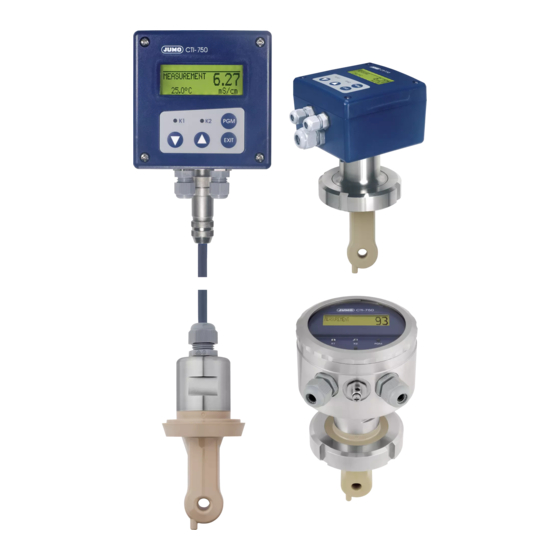
JUMO CTI-750 Operating Instructions Manual
Inductive conductivity/concentration and temperature transmitter with switch contacts
Hide thumbs
Also See for CTI-750:
- Operating instructions manual (68 pages) ,
- Operating manual (76 pages) ,
- Operating manual (88 pages)

Related Manuals for JUMO CTI-750


Summary of Contents for JUMO CTI-750
- Page 1 JUMO CTI-750 Inductive Conductivity/Concentration and Temperature Transmitter with switch contacts B 202756.0 Operating Instructions 2013-07-25/00452846...
- Page 2 WARNING! A sudden failure of the instrument or of a sensor connected to it could result in dangerous overdosing. Please take suitable precautionary measures for this case. NOTE! All the nececssary settings are described in this manual. However, if any difficulties should arise during start-up, please do not carry out any unauthorized manipulations.
-
Page 3: Table Of Contents
Contents Typographical conventions ............5 Warning signs ....................5 Note signs ....................5 General ..................6 Preface ......................6 Device configuration ..................6 Inductive conductivity measurement ........8 Area of application ..................8 Function .......................9 Instrument identification ............10 Nameplate ....................10 Type designation ..................11 The device as "Head transmitter" ..............11 The device as "Transmitter with separate sensor"... - Page 4 Contents Operation ................. 44 10.1 Controls ......................44 10.2 Principle of operation .................46 10.3 Principle of operation .................48 10.4 Measurement mode ...................49 10.5 Operator level .....................49 10.6 Administrator level ..................57 10.7 Calibration level ..................59 10.8 Dilution function ..................60 Calibration ................64 11.1 General .......................64 11.2...
-
Page 5: Typographical Conventions
1 Typographical conventions Warning signs DANGER! This symbol is used when there may be danger to personnel if the instruc- tions are ignored or not followed correctly! CAUTION! This symbol is used when there may be damage to equipment or data if the instructions are ignored or not followed correctly! Note signs NOTE! -
Page 6: General
2 General Preface Please read these operating instructions before commissioning the inst- rument. Keep the manual in a place that is accessible to all users at all times. NOTE! All necessary settings are described in this manual. However, if any difficul- ties should still arise during start-up, please do not carry out any unauthori- zed manipulations. - Page 7 2 General 2.2.2 Device with separate sensor Example Transmitter (with and without graphic LCD display) Process connection Temperature probe Inductive conductivity measurement sensor...
-
Page 8: Inductive Conductivity Measurement
3 Inductive conductivity measurement Area of application General The inductive measurement method permits largely maintenance-free acquisition of the specific conductivity, even in difficult media conditions. Unlike the conductive measurement method, problems such as electrode decomposition and polarization do not occur. Brief description The instrument is used for the measurement/control of conductivity or concentration in liquid media. -
Page 9: Function
3 Inductive conductivity measurement Function of the transmitter The instrument has been designed for use on site. A rugged housing protects the electronics and the electrical connections from corrosive environmental conditions (enclosure IP67). As standard, the device has one analog signal output each for conductivity/concentration and temperature respectively. -
Page 10: Instrument Identification
4 Instrument identification Nameplate on the transmitter JUMO GmbH & Co. KG Fulda, Germany www.jumo.net JUMO CTI-750 Type: 202756/15-607-0000-82/767,941 VARTN: 20/00544540 F No.: 12345678 01 0 1203 0001 DC 19...31 V on the connecting cable (only with separate sensor) CAUTION! -
Page 11: Type Designation
4 Instrument identification Type designation The device as "Head transmitter" Basic type 202756 Inductive transmitter/switching device for conductivity/ concentration and temperature Basic type extension Head transmitter in plastic housing, without display/keypad Head transmitter in plastic housing, with display/keypad Head transmitter in stainless steel housing, with display/keypad Process connection Thread G 1 1/4 A Thread G 1 1/2 A... -
Page 12: The Device As "Transmitter With Separate Sensor
4 Instrument identification Order code , ... Order example 202756 0000 List extra codes in sequence, separated by commas. The device as "Transmitter with separate sensor" Basic type 202756 Inductive transmitter/switching device for conductivity/ concentration and temperature Basic type extension a, b Transmitter in plastic housing, without display/keypad (without sensor) Transmitter with display/keypad (without sensor) - Page 13 4 Instrument identification Electrical connection Fixed cable with M12 socket connector on separate sensor Cable glands on the operating unit M12 plug/socket connectors on operating unit Two M16 cable glands and a blind grommet Extra code No extra code Internal temperature sensor Cell material PEEK Cell material PVDF Supply voltage 24 V AC...
- Page 14 4 Instrument identification Accessories Type Part No. Flange DN 32, material: PP 00083375 Flange DN 50, material: PP 00083376 Weld-on threaded adapter DN 50, DIN 11851 00085020 Adapter Clamp 1“ - 1,5“ to G 1 00530354 Adapter MK DN 50 to G 1 00530355 Ring nut DN 50, DIN 11851 00343368...
-
Page 15: Instrument Description
5 Instrument description Technical data 5.1.1 Conductivity transmitter A/D converter Resolution 15 bits Sampling time 500 ms = 2 measurements/s Power supply For SELV and PELV circuit operation only. Standard 19 - 31 V DC (24 V DC nominal) Residual ripple <5 % Reverse polarity protection Extra code 844... - Page 16 5 Instrument description Dependent on version and process connection 5.1.2 Measuring ranges There is a choice of four different measuring ranges. Any one of these ranges can be activated by an external switch or by a PLC. NOTE! The overall accuracy is composed of transmitter accuracy plus sensor accuracy.
-
Page 17: Temperature Compensation
5 Instrument description 5.1.3 Temperature transmitters Temperature acquisition Manually, -20.0 to 25.0 to 150 °C or °F, or automatically Measuring range -20 - 150 °C or °F Characteristic linear ≤ 0.5 % of the measuring range Accuracy ≤ 0.1 %/K Ambient temperature effect Output signal 0 - 10 V or 10 - 0 V... - Page 18 5 Instrument description 5.1.5 Inductive conductivity sensor Measuring range Accuracy (as % of measuring range span) ≤ 1 % 0 - 500 µS/cm ≤ 1 % 0 - 1000 µS/cm ≤ 0,5 % 0 - 2000 µS/cm ≤ 0,5 % 0 - 5000 µS/cm ≤...
-
Page 19: Installation
6 Installation General 6.1.1 Installation location Make sure that the site is readily accessible, for calibration at a later time. The fixing must be secure and free from vibration. Avoid direct sunlight! Take care that there is adequate flow through and around the sensor (2)! If the device is to be mounted in a pipeline, there must be at least 20 mm clearance between the sensor and the wall of the pipe. -
Page 20: Head Transmitter Dimensions
6 Installation Head transmitter dimensions 6.2.1 Operating device Head transmitter in a plastic casing for basic type extensions 10 or 15 and electrical connection 83 M12 flush-type connector M12 flush-type connector 5-pin 8-pin M12 socket (PBT / PA) M12 flush-type connector 8-pin 6.2.2 Process connections Version with process connection... - Page 21 6 Installation 2 (607) Version with process connection Version with process connection 607 = MK DN 50 606 = MK DN 40 608 = MK DN 65 607 = MK DN 50 609 = MK DN 80 608 = MK DN 65 and extra code 767 609 = MK DN 80 and extra code 768...
- Page 22 6 Installation 1 (617) 2 (616) Version with process connection Version with process connection 616 = Clamp 2" 617 = Clamp 2 1/2" 617 = Clamp 2 1/2" and extra code 768 and extra code 767 and 941 (retaining clip not included in delivery) (retaining clip not included in delivery) Version with process connection ®...
- Page 23 6 Installation < 200Nm < 200Nm Version with process connection Version with process connection 690 = SMS 2" 690 = SMS 2" and extra code 767 and 941 and extra code 768 ( < 20Nm) ( < 20Nm) Version with process connection Version with process connection 955 = Pressing screw G 1"...
-
Page 24: Device With Separate Sensor
6 Installation Device with separate sensor 6.3.1 Operating device Transmitter with a separate sensor, in a plastic casing with basic type extensions 26 or 66 and electrical connection 83 6.3.2 Drilling template for wall mounting Knock-through plugs (×4) Venting element, PBT... -
Page 25: Process Connections
6 Installation 6.3.3 Process connections Version with process connection Version with process connection 108 = screw-in thread G 1 1/2 A 107 = screw-in thread G 1 1/4 A 110 = screw-in thread G 2 A 108 = screw-in thread G 1 1/2 A and extra code 767 110 = screw-in thread G 2 A and extra code 768... - Page 26 6 Installation 2 (607) Split version with process connection Split version with process connection 607 = MK DN 50 606 = MK DN40 608 = MK DN 65 607 = MK DN50 609 = MK DN 80 608 = MK DN65 and extra code 767 609 = MK DN80 (retaining clip not included in delivery)
- Page 27 6 Installation 1 (617) 2 (616) Split version with process connection Split version with process connection 616 = Clamp 2" 617 = Clamp 2 1/2" 617 = Clamp 2 1/2" and extra code 768 and extra code 767 (retaining clip not included in delivery) (retaining clip not included in delivery) 1 = stainless steel 1.4301 2 = PEEK...
- Page 28 6 Installation Split version with process connection Split version with process connection 690 = SMS 2" 690 = SMS 2" and extra code 767 and extra code 768 (retaining clip not included in (retaining clip not included in < 200Nm) <...
- Page 29 6 Installation ® Varivent < 20Nm < 20Nm Split version with process connection Split version with process connection 955 = Pressing screw G 1" 956 = Pressing screw G1" < 20Nm) < 20Nm) EL = 57 mm EL = 87 mm and extra code 767 and extra code 767 1 (617)
- Page 30 6 Installation ø18 ø100 ø165 Optional accessory DN 32 Flange Part no. 00083375 ø18 ø125 ø165 Split version Optional accessory with process connection 706 DN 50 Flange immersion model Part no. 00083376 (pipe clips not included in delivery) 3 = PVDF 6 = PBT 7 = brass nickel plated EPDM...
-
Page 31: Mounting Examples
6 Installation Mounting examples Threaded pipe adapter Process connection 607, screwed pipe fitting DN 50, DIN 11851 (MK DN 50, milk cone), PEEK Ring nut DN 50, 1.4301 Weld-on threaded pipe adaptor DN 50, DIN 11851, 1.4301 (matching part for process connection 607) Tee DIN 11852, short, DN50, 1.4301 (to be provided by the plant operator;... - Page 32 6 Installation Clamp Process connection 617, Clamp 2 1/2", PEEK Clamping ring, 1.4301, Tee, short, 2.5" - 2" similar to DIN 11852, and 2" clamp adapter, 1.430 (to be provided by the plant operator; not supplied by the device manufacturer) ®...
- Page 33 6 Installation Pressing screw G 1 A to threaded pipe adapter DN 50 Process connection adapter Pressing screw G 1 A to threaded pipe adapter DN 50, DIN 11851 Tee DIN, short , SSS DN 65/50, 1.4301 (to be provided by the plant operator; not supplied by the device manufacturer) Pressing screw G 1 A to Clamp 1"...
- Page 34 6 Installation 6.4.1 Pipe-mounting kit NOTE! The pipe-mounting kit is also suitable for horizontal pipes. for type 202756, part no. 00515128 for type 202756, part no. 00515128...
-
Page 35: Installation
7 Installation ATTENTION! The electrical connection must only be carried out by properly qualified personnel! • The choice of cable, the installation and the electrical connection must conform to the requirements of VDE 0100 “Regulations on the Installation of Power Circuits with Nominal Voltages below 1000 V” or the appropriate local regulations. -
Page 36: General
7 Installation General Opening the operating unit ATTENTION! It is only necessary to open the housing for devices with cable glands. Devices with M12 plug/socket connectors should not be opened! ✱ Remove four screws (1) and take off the cover Connecting up the cables SETUP e-cond. -
Page 37: Electrical Connection
7 Installation ATTENTION! To connect the single conductors, pull off the pluggable screw terminals (1) in the operating unit. Pass the connecting cables through the cable glands (2). Wiring DANGER! For devices with a separate sensor, the transmitter and detached sensor are matched to one another at the factory! When connecting the components, please note that the serial number of the external sensor (marked on the label attached to the connecting cable) must... - Page 38 7 Installation Transmitter with separate sensor Power supply and actual value output (conductivity/concentration and temperature) M12 cable gland (PA) Separate sensor M12 flush-type connector Binary input and switching outputs M12 cable gland (PA) SETUP e-cond. e-temp. 9 10 11 12 13 14 Terminal assignment Symbol Supply...
- Page 39 7 Installation Terminal assignment Symbol Foto-MOS-Relay K1 (floating, no) Foto-MOS-Relay K2 (floating, no) Binary inputs Binary input E1 Binary input E2 7.2.2 Transmitter with electrical connection 83 (M12 plug-and-socket connection) Head transmitter Connector I Power supply and actual value output for conductivity/concentration M12 flush-type connector, 5-pin Blanking plug Connector II...
- Page 40 7 Installation Transmitter with separate sensor Connector I Power supply and actual value output for conductivity/concentration M12 flush-type connector, 5-pin Connector III Inductive conductivity sensor M12 flush-type connector, 8-pin Connector II Actual value output for temperature, and binary input and switching outputs M12 flush-type connector, 8-pin ATTENTION! In devices with a separate sensor and M12 plug / socket connectors, the...
- Page 41 7 Installation Binary inputs Binary input E1 Conn. II Conn. I Binary input E2 Conn. II Conn. I DANGER! The ground connector at the case must be connected with the functional earth (EN 60445). A steel piping must be connected with functional earth (EN 60445)!
-
Page 42: Setup Program
8 Setup program Function Configurable parameters The setup program, which is available as an option, can be used for easy adaptation of the transmitter to specific requirements. • Setting the measurement range and the range limits. • Setting the response of the output to an out-of-range signal. •... -
Page 43: Commissioning
9 Commissioning CAUTION! The transmitter has been tested in the factory for fault-free functioning, and is delivered ready for operation. Head-mounted transmitter or transmitter with separate sensor ✱ Mounting the instrument, see “Installation”, page 19. ✱ Connecting the instrument, see “Installation”, page 35. DANGER! For devices with a separate sensor, the transmitter and detached sensor are matched to one another at the factory! -
Page 44: Operation
10 Operation 10.1 Controls Device without LC display Device with LC display Grafik LC display, back-lit key, confirm entries/select menu key, cancel entry without saving/cancel calibration go back one EXIT menu level key, increase value/step on in selection key, reduce value/step on in selection LEDs K1 and K2 show the states of the switched outputs. - Page 45 10 Operation LC display (11) (10) Output K1 is activ Output K2 is activ Binary input 1 is activated Binary input 2 is activated Keypad is inhibited Device status (indications) • Alarm (e.g. overrange) • Calib blinking (calibration timer has run down) •...
-
Page 46: Principle Of Operation
10 Operation 10.2 Principle of operation 10.2.1 Operation in levels Measurement mode, see Chapter 10.4 "Principle of operation" page 39 OPERATOR LEVEL, see chapter 10.5 "Operator level", page 39. INPUT CONDUCTIVITY MEASUREMENT RANGE 1...4 TEMPERATURE COMPENSATION TEMP. COEFFICIENT 1...4 REFERENCE TEMPERATURE REL. - Page 47 10 Operation DEVICE DATA LANGUAGE CONTRAST LIGHTING INVERTING LCD ADMINISTR. LEVEL, see chapter 10.6, "Administrator level", page 47 Password PARAMETER LEVEL, see chapter 10.6.1 "Parameter level" page 48. INPUT CONDUCTIVITY OUTPUT CONDUCTIVITY INPUT TEMPERATURE OUTPUT TEMPERATURE OUTPUT BINARY 1 OUTPUT BINARY 2 INPUT BINARY 1 INPUT BINARY 2 DILUTION FUNCTION...
-
Page 48: Principle Of Operation
10 Operation 10.3 Principle of operation Operation in levels... -
Page 49: Measurement Mode
10 Operation 10.4 Measurement mode Representation In measurement mode, the conductivity is shown (compensated for the refe- rence temperature) or the concentration and temperature of the medium being measured. MEASUREMENT -> Measurement mode 20.5°C -> Temperature of the sample medium 203 mS/cm ->... - Page 50 10 Operation 10.5.1 CONDUCTIVITY IN (conductivity input) RANGE 1 — 4 0 — 500 µS/cm 0 — 1000 µS/cm 0 — 2000 µS/cm 0 — 5000 µS/cm 0 — 10 mS/cm 0 — 20 mS/cm 0 — 50 mS/cm 0 — 100 mS/cm 0 —...
- Page 51 10 Operation CONC. MEAS. TYPE NO FUNCTION NaOH HNO3 CUSTOMIZED (values can only be entered by using the optional setup program) CONC. MEAS. RANGE For HNO 0 — 25 % BY WEIGHT 36 — 82 % BY WEIGHT For NaOH 0 —...
- Page 52 10 Operation 10.5.2 CONDUCTIVITY OUT (conductivity output) SIGNAL TYPE 0 — 20 mA 4 — 20 mA 20 — 0 mA 20 — 4 mA 0 — 10 V 2 — 10 V 10 — 0 V 10 — 2 V SCALING START 1 —...
- Page 53 10 Operation 10.5.3 TEMPERATURE IN DIMENS. UNIT °C °F MEAS. MODE SENSOR MANUAL MANUAL VALUE -20.0 to 25.0 to 150 °C OFFSET -15.0 to 0.0 to 15.0 °C FILTER TIME 00:00:00 — 00:00:01 — 00:00:25 H:M:S 10.5.4 TEMPERATURE OUT SIGNAL TYPE 0 —...
- Page 54 10 Operation MANUAL MODE MAN. VALUE 0.0 — 4.0 — 22.0 mA (depending on the signal type) 0 — 10.7 V 10.5.5 BINARY OUTPUT 1 and BINARY OUTPUT 2 FUNCTION NO FUNCTION MIN. CONDUCT. MAX. CONDUCT. LK1 CONDUCT. LK2 CONDUCT. MIN.
- Page 55 10 Operation Pulse contact Pulse contact Trigger condition longer than Trigger condition shorter than pulse duration pulse duration LIMIT -20.0 — 999.0 (depending on the function, see above) HYSTERESIS 0.0 — 1.0 — 999.0 (depending on the function, see above) SPACING 0.0 —...
- Page 56 10 Operation 10.5.6 BINARY INPUT 1 and BINARY INPUT 2 FUNCTION NO FUNCTION HOLD/LOCK KEY RANGE/TEMPCO. DILUTION Setting parameters Binary input 1 Binary input 2 Range/temperature Range1/TC1 open open coefficient changeover Range2/TC2 closed open Range3/TC3 open closed Range4/TC4 closed closed Key inhibit closed Hold function...
-
Page 57: Administrator Level
10 Operation 10.5.8 INSTRUMENT DATA LANGUAGE GERMAN ENGLISH FRENCH SPANISH POLISH SWEDISH ITALIAN PORTUGUESE DUTCH RUSSIAN NOTE! Entering the password 7485 in the administrator level will reset the opera- ting language to English. CONTRAST 0 — 6 — 11 LIGHTING IF OPERATED (approx. - Page 58 10 Operation Levels within the administrator level 10.6.1 Parameter level The administrator can edit all parameters for the operator level in this level. The structure “Parameter level” within the administrator level is identical to the operator level, see “Operator level”, page 49 and the following. 10.6.2 Enable level In this level, the administrator can define which parameters can be altered or edited by the operator in the operator level.
-
Page 59: Calibration Level
10 Operation 10.7 Calibration level All the calibrations that have been enabled by the administrator (administrator level) can be carried out in this level. ✱ Press the key for at least 3 seconds. ✱ Use the key to select CALIBRATION LEVEL. 10.7.1 REL. -
Page 60: Dilution Function
10 Operation 10.8 Dilution function Brief description For cooling water, the conductivity is used to deduce the total salt content. If a conductivity limit is reached (at the maximum permissible salt content/con- centration), then the cooling water must be diluted. A dilution valve is opened, the concentrated water flows out, and is replaced by fresh water. - Page 61 10 Operation 10.8.1 Stop dilution All the parameters are system-dependent, and must be adjusted to suit sys- tem requirements. ✱ Press the key for at least 3 seconds. ✱ Use the key to select OPERATOR LEVEL; use the key to confirm the selection.
- Page 62 10 Operation ✱ Change to the operator level, using the key. EXIT ✱ Use the key to select DILUTION. ✱ Confirm the selection with the key. ✱ Use the key to set the dilution factor in the range from 1 — 10 — 50 % below the limit value. ✱...
- Page 63 10 Operation ✱ Set the lock time with the key in the range from 0:00:00 — 00:01:00— 18:00:00 H:M:S. ✱ Confirm the setting with the key. NOTE! If there is an interruption in the supply voltage during dilution, the function will be canceled.
-
Page 64: Calibration
11 Calibration 11.1 General The device offers various calibration options to increase the precision. NOTE! The conductivity sensor should be cleaned and calibrated at regular inter- vals, depending on the medium being measured. The K1 LED blinks during calibration. 11.2 Calibrating the relative cell constant In order to meet enhanced demands for precision, the cell constant must first be calibrated. - Page 65 11 Calibration ✱ Use the key to select REL. CELL CONSTANT; use the key to confirm the selection. ✱ When the measurement is stable, press the key. ✱ Use the key to correct the indicated uncompensated conductivity to match the known value for the reference solution. ✱...
-
Page 66: Calibrating The Temp. Coefficient Of The Sample Solution
11 Calibration 11.3 Calibrating the temp. coefficient of the sample solution 11.3.1 Linear temperature coefficient (ALPHA) The conductivity of any sample solution will change according to its individual temperature coefficient. We therefore recommend carrying out a calibration of the temperature coefficient. - Page 67 11 Calibration ✱ Use the key to enter the working temperature; confirm with the key. NOTE! The working temperature must be at least 5 °C above or below the refe- rence temperature (25.0 °C). The LC display now shows selected working temperature (blinking) reference temperature (blinking) present sensor temperature (steady) ✱...
- Page 68 11 Calibration The LC display now shows the derived temperature coefficient in %/°C. To accept the temperature coefficient that has been determined -> press the key for at least 3 seconds or to reject the value -> press the key. EXIT The transmitter is in the calibration menu.
- Page 69 11 Calibration 11.3.2 Non-linear temperature coefficient (ALPHA) General Since the temperature coefficient of some media is not constant over a sizeable temperature range, the device provides the option of subdividing a temperature range (T to T ) into 5 sections. A different TC value can be Start used for compensation in each of these range sections.
- Page 70 11 Calibration TC curve Temperature compensation with the TC curve The present temperature of the medium is applied to the TC curve to deter- mine the corresponding temperature coefficient, see “TC curve”, page 70. Intermediate values, e.g. (α at T ) between two known values (α...
- Page 71 11 Calibration Sequence for automatic calibration The TC curve is automatically recorded over a temperature range that has been defined by the user. The temperature range between the start and end temperatures is subdivided into 5 sections of equal size. The temperature range must be larger than 20 °C, and cover the reference temperature.
- Page 72 11 Calibration ✱ Use the key to enter the start temperature; confirm with the key. NOTE! The start temperature must be lower than the reference temperature (25.0 °C). ✱ Use the key to enter the end temperature; confirm with the key.
- Page 73 11 Calibration ✱ Warm up the sample medium until is it above/below the temperature that is blinking. The next target measured temperature is displayed as blinking. CAUTION! During calibration, the rate of change of temperature for the sample solution must not exceed 10 °C/min for a device with exposed temperature sensor, or 1 °C/min for a device with an internal temperature sensor.
-
Page 74: Maintenance
12 Maintenance 12.1 Cleaning the conductivity sensor CAUTION! Do not use solvents. Hard-to-remove crusts and deposits can be softened and removed with dilute hydrochloric acid. Observe the safety regulations! Deposits Deposits on the sensor section can be removed with a soft brush (e.g. a bottle brush). -
Page 75: Eliminating Faults And Malfunctions
13 Eliminating faults and malfunctions Possible errors Problem Possible cause Measures No measurement display Supply voltage Check supply voltage, also check or signal output missing terminals Measurement display 000 or Sensor not immersed in Top up the reservoir signal output 0 % medium, reservoir level (e.g. -
Page 76: Checking The Instrument
13 Eliminating faults and malfunctions 13.1 Checking the instrument General The instrument is calibrated at the factory, and is maintenance-free. If, never- theless, measurement deviations appear with no apparent cause, the transmit- ter can be tested as follows. 13.1.1 Resistance loop test Cell constant CAUTION! The cell constant of the device is type-dependent! - Page 77 13 Eliminating faults and malfunctions ✱ Connect resistor R to wire Calculating resistance Formula for calculating the resistance of the resistor loop: · K resistance of resistor loop number of loop windings cell constant required display in S/cm Note: 1 mS/cm = 1·10-3 S/cm 1 µS/cm = 1·10-6 S/cm For display values up to 20 mS, the resistor loop must have one winding.
- Page 78 13 Eliminating faults and malfunctions Pre-calculated values Display value 0 is obtained if the following conditions are met: • the sensor is dry and • the sensor does not have any conductive coatings and • a resistor loop is not installed. Display at Number Cell constant...
- Page 79 13 Eliminating faults and malfunctions 13.1.2 Reference liquid test Immerse in test solution Test sequence ✱ Prepare the conductivity test solution in a container of adequate size. ✱ Connect up the device, see Chapter 7 “Installation”, page 35. ✱ Select the range appropriate to the conductivity test solution, see Chapter 10.5.1 “CONDUCTIVITY IN (conductivity input)”, page 50 ->...
- Page 80 13 Eliminating faults and malfunctions 13.1.3 Reference measuring instrument test Immerse in test solution Test sequence ✱ Prepare the conductivity test solution in a container of adequate size. ✱ Connect up the device, see Chapter 7 “Installation”, page 35. ✱ Select the range appropriate to the conductivity test solution, see Chapter 10.5.1 “CONDUCTIVITY IN (conductivity input)”, page 50 ->...
-
Page 81: Appendix
14 Appendix 14.1 Before configuration If a number of instrument parameters have to be modified in the instrument, then it is advisable to note them in the table below, and then modify these parameters in the sequence given. NOTE! The following list shows the maximum number of parameters that can be altered. - Page 82 14 Appendix Parameter Selection/value range see page Factory setting setting Conductivity output Signal type 0 — 20 mA 4 — 20 mA 20 — 0 mA 20 — 4 mA 0 — 10 V 2 — 10 V 10 — 0 V 10 —...
- Page 83 14 Appendix Parameter Selection/value range see page Factory setting setting During alarm high safe value During calibration moving frozen safe value Safe value 0.0 — 4.0 — 22.0 mA Manual mode Manual value 0.0 — 4.0 — 22.0 mA Binary output 1 or binary output 2 Function no function conductivity MIN contact...
- Page 84 14 Appendix Parameter Selection/value range see page Factory setting setting Lock time 00:00:00 — 00:01:00 — 18:00:00 H:M:S Device data Language German English French Spanish Polish Swedish Italian Portuguese Dutch Russian Contrast 0 — 6 — 11 Lighting during operation LCD inverse...
- Page 88 JUMO GmbH & Co. KG JUMO Instrument Co. Ltd. JUMO Process Control, Inc. Street address: JUMO House 6733 Myers Road Moritz-Juchheim-Straße 1 Temple Bank, Riverway East Syracuse, NY 13057, USA 36039 Fulda, Germany Harlow - Essex CM20 2DY, UK Phone:...
Need help?
Do you have a question about the CTI-750 and is the answer not in the manual?
Questions and answers