
Related Manuals for JUMO ecoTRANS pH 03


Summary of Contents for JUMO ecoTRANS pH 03
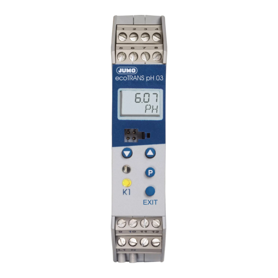
- Page 1 JUMO ecoTRANS pH 03 Microprocessor/transmitter / switching device for pH value / redox voltage and temperature Operating manual 20272300T90Z001K000 V2.00/EN/00506536...
-
Page 3: Table Of Contents
Content Typographical conventions ......6 Warning signs ......... . 6 Note signs . - Page 4 Content Calibration ........40 General information ........40 9.1.1 When is calibration required? .
- Page 5 Display and LED messages ..... . . 62 12.1 Operating states of JUMO ecoTrans pH 03 ....62 12.2 Underrange .
-
Page 6: Typographical Conventions
1 Typographical conventions Warning signs Danger This symbol is used when there may be danger to personnel if the instructions are ignored or not followed correctly! Caution This symbol is used when there may be damage to equipment or data if the instructions are ignored or not followed correctly! Caution This symbol is used where special care is required when handling components... -
Page 7: Notes
Please assist us in improving these operating instructions where necessary. For technical questions Service hotline: Phone: 0661 6003-300 or 0661 6003-653 Fax: 0661 6003-881300 or 0661 6003-881653 E-mail: Service@jumo.net... -
Page 8: Identifying The Instrument Version
3.1 Type description (1) Basic type 202723 JUMO ecoTRANS pH 03, Microprocessor/transmitter / switching device for pH value / redox voltage and temperature (2) Output I (pH value / redox voltage) Analog actual value output, freely programmable... -
Page 9: Mounting
4 Mounting °C ≤ 75 5 Electrical connection The choice of cable, the installation, and the electrical connection must conform to the requirements of VDE 0100 “Regulations on the Installation of High-Voltage Systems with Nominal Voltages below 1000 V” or the appropriate local regulations. To protect the device from static electrical discharge, the user must be electrostatically discharged before touching the instrument! -
Page 10: Connecting The Sensor
5.1 Connecting the sensor To connect the pH redox electrode, special coaxial lines are recommended as specified by JUMO datasheet 202990. Standard commercial antenna or computer lines with coaxial construction are generally not suitable. They may result in faulty readings or could destroy the pH or redox electrode. -
Page 11: Customizing The Special Coaxial Line
5.2 Customizing the special coaxial line Example: ~40 mm Strip insulation from the line as shown in the drawing. Remove the black semiconducting layer (2) from the insulation of the inner conductor as indicated. Twist the shield (1) and insulate with a shrink tubing. Insulate the black semiconducting layer with shrink tubing (2) to prevent short circuits. - Page 12 Terminal assignment EXIT...
- Page 13 Measurement Terminal assignment Symbol inputs pH electrode Reference system (braiding) Redox Glass electrode/metal combination electrode (inner conductor) electrode pH glass electrode 13 Glass electrode/metal electrode (inner conductor) Metal electrode (with isolated reference electrode) Reference 16 Reference system electrode (with isolated electrodes) Liquid potential (connect only with...
- Page 14 Binary input Outputs Terminal assignment Symbol Analog process value output pH/ redox (galvanically isolated) Analog process value output - temperature (galvanically isolated) Relay Break (SPST-NC) Make (SPST-NO) Ö Power Terminal assignment Symbol supply Power supply (with reverse polarity protection) DC 20 to 30 V...
-
Page 15: Commissioning
6 Commissioning 6.1 Brief description of the instrument The instrument measures and, depending on the configuration, regulates the pH or redox voltage in aqueous solutions. The range applications includes general water wastewater management, measuring drinking and wastewater, process water, surface and ocean water, swimming pool and fountain water, and professional aquariums, etc. -
Page 16: Block Diagram
Note: After the instrument is started, the output signal is 0 V or 0 mA. The relay is in idle state (inactive). After about 2 seconds, the JUMO ecoTRANS pH 03 begins working according to the configuration. -
Page 17: Adjusting / Changing Instrument Functions
7 Adjusting / changing instrument functions Changes can be made in the setup program or with the JUMO ecoTRANS pH 03 keys. 7.1 Process value display The process value display can be either - in static mode or in - alternating mode... -
Page 18: Operation
7.2 Operation The instrument can be operated on different levels. Access to all levels (except the user level) is protected by different codes On the User level (USER) all parameters can be viewed and/or modified depending on user rights (see Enable level). On the Calibration level (CALIB) the electrode zero point (intercept point) and/or the electrode slope can be calibrated. - Page 19 - To increase or reduce the value, press the UP or DOWN key. - The value can then be accepted with the P key. - The EXIT key is used to cancel the entry and switch to the next higher level.
-
Page 20: Selecting Levels
7.4 Selecting levels Process value display > 2 seconds EXIT Selection level EXIT USER (Operator level) EXIT ADMIN (Administrator level) EXIT RIGHT (Enable level) EXIT CALIB (Calibration level) Timeout (automatically jumps back after 60 sec. with no activity). See Section 7.5 "User level (USER)", page 21. See Section 7.6 "Administrator level (ADMIN)", page 22. -
Page 21: User Level (User)
7.5 User level (USER) -
Page 22: Administrator Level (Admin)
7.6 Administrator level (ADMIN) -
Page 23: Enable Level (Right)
7.7 Enable level (RIGHT) -
Page 24: Calibration Level (Calib)
7.8 Calibration level (CALIB) CALIB CODE See Section 9.5.1 "One-point calibration (zero point)", page 44 NULL See Section 9.5.2 "Two-point calibration (zero point and slope)", page 45 SLOPE The timeout function is not active during calibration! See Section 9 "Calibration", page 40. -
Page 25: Configurable Parameters
8 Configurable parameters Parameters can be set with the setup program or on the instrument. Since some parameters are independent of each other, it may be necessary when one parameter is changed to adjust others as well. Example: When the measurement variable is changed (from pH to redox voltage or vice versa) the display format, setpoints, and other parameters are adjusted. -
Page 40: Calibration
9 Calibration 9.1 General information The zero point (intercept) and slope of pH sensors stray from copy to copy. During the service life of the sensor, up to the time it must be replaced by a new sensor, the zero point and slope change. To allow for precise measurements, the transmitter must be adjusted (calibrated) to the current sensor parameters. -
Page 41: Starting Calibration From The Calibration Level "Calib
Calibration can be cancelled at any time with the EXIT key. Old calibration data will not be lost. Calibration is performed using the instrument keys. The zero point and slope of a sensor can also be entered manually. This should only be done in exceptional cases. -
Page 42: Canceling Calibration And Error Messages
9.3 Canceling calibration and error messages Calibration can be cancelled at any time with the EXIT key. Old calibration data will not be lost. During the calibration process, the transmitter calculates the electrode parameters zero point and if applicable slope. If the calculated values fall outside the permissible parameter limits, an error message is generated. -
Page 43: Acknowledging Errors
The parameter limits for NULL and SLOPE have been violated and/ or the two calibration points Ref.1 and Ref.2 are too close to each other. For two-point calibration of a pH sensor, the minimum spacing is 2 pH. For two-point calibration of a redox sensor, the minimum spacing is 2 mV. -
Page 44: Selecting Two-Point Calibration
9.4.2 Selecting two-point calibration Press the key and select CAL 2-PT. For more details see Section 9.5.2 "Two-point calibration (zero point and slope)", page 45. 9.5 Calibrating a pH measurement chain 9.5.1 One-point calibration (zero point) Confirm the selection with Display or editing option of the buffer temperature. -
Page 45: Two-Point Calibration (Zero Point And Slope)
Flashing Enter the actual buffer value with and confirm with The calculated zero point of the measurement chain appears. Accept the value with or press to cancel the calibration. EXIT The instrument goes into measurement mode. If an error message appears, see Section 9.3 "Canceling calibration and error messages", page 42. - Page 46 Confirm the selection with Display and editing option of the buffer temperature. Confirm the selection with The first reference value is then measured. Immerse the measurement chain in the first buffer (for example pH 7.00) Wait until the measurement value has stabilized. Confirm the measurement value with Flashing Enter the actual buffer value with...
- Page 47 Remove the measurement chain from the first buffer and rinse with distilled water. Immerse the measurement chain in the second buffer (for example pH 4.00) Wait until the measurement value has stabilized. Confirm the measurement value with Flashing Enter the actual buffer value with confirm with The calculated zero point (top line) and the calculated slope (bottom line) appear.
-
Page 48: Ph Antimony Measurement Chain
9.6 pH antimony measurement chain Antimony measurement chains are calibrated similarly to "normal" pH measurement chains, see Section 9.5 "Calibrating a pH measurement chain", page 44. 9.7 Redox measurement chain 9.7.1 General information The instrument offers two calibrating options for adjusting it to the redox measurement chain. - Page 49 The reference value is then measured. Wait until the measurement value has stabilized. Confirm the measurement value with Flashing Enter the actual buffer value with confirm with The calculated zero point of the measurement chain appears. Accept the value with or press to cancel the calibration.
-
Page 50: Two-Point Calibration
9.7.3 Two-point calibration In this type of calibration the display range can be scaled freely from 0 to 100%. Example: A span of -10 mV ... +1000 mV can be scaled to 0 ... 100% werden. The zero point can fall within the range of -999 ... - Page 51 Enter the desired value with (for example 20) and confirm with Remove the measurement chain from the first solution and rinse with distilled water. Immerse the measurement chain in the second solution (for example 295 mV). Wait until the measurement value has stabilized. Confirm the measurement value with Flashing Enter the desired value with...
-
Page 52: Analog Output
10 Analog output Analog outputs are configured on the user level (USER) or on the administrator level (ADMIN) in PH.OUT redox output) TE.OUT (temperature output); see Section 7.5 "User level (USER)", page 21. 10.1 Behavior of the output signal during calibration Two options are possible, "Concurrent"... -
Page 53: Output Signal In Case Of Error
10.3 Output signal in case of error Depending on the configuration, the output signal may assume the "LOW" or "HIGH" state in case of error. Output signal Output signal Output signal nominal HIGH 0...20 mA 22.0 mA 0 mA 4...20 mA 22.0 mA 3.4 mA 0...10 V... -
Page 54: Relay Output
11 Relay output 11.1 Relay behavior Depending on the setting, the JUMO ecoTRANS pH 03 monitors a limit value. 11.2 Binary output 1 (submenu "BIN.1") Setting options = No function (default setting) = Window contact main value (active inside a window) - Page 55 Contact function for settings 1 and 5 Hysteresis HYS.1. Distance DST.1 Switching point ALAR.1 Contact function for settings 2 and 6 Hysteresis HYS.1. Distance DST.1 Switching point ALAR.1...
- Page 56 Contact function for settings 3 and 7 Hysteresis HYS.1. Switching point ALAR.1 Contact function for settings 4 and 8 Hysteresis HYS.1. Switching point ALAR.1...
-
Page 57: Manual Mode Of The Relay Output
11.3 Manual mode of the relay output For test purposes or when starting up systems, a constant signal can be generated by the transmitter. Manual mode can be set with parameter: USER / BIN.1 / SIM.1 to = inactive = active => LED "K1" is lit = No manual mode. -
Page 58: Behavior Of The Relay During Calibration
After "Supply voltage On" manual mode is always deactivated. 11.4 Behavior of the relay during calibration The behavior of the relay with the parameter: USER / BIN.1 / CAL.1 set to Relay inactive Relay active Relay unchanged (during calibration the relay status remains set to the status that was valid before the calibration process) 11.5 Pulse function of the relay output The limit comparator is reset after an adjustable "pulse time."... - Page 59 Triggering condition is longer than pulse duration Triggering condition Time Pulse contact Time Pulse duration T.PUL1 Triggering condition is shorter than pulse duration Triggering condition Time Pulse contact Time Pulse duration T.PUL1...
-
Page 60: Behavior Of The Relay In Case Of Error
11.6 Behavior of the relay in case of error The behavior of the relay can be adjusted with the following parameters: USER / BIN.1 and ERR.1 set to Relay inactive Relay active Relay unchanged ("frozen": the relay status remains set to the status that was valid before the error) Function pH value... - Page 61 Limit comparator of pH value/redox voltage with active temperature compensation - Underrange pH value/redox voltage - Overrange pH value/redox voltage - Underrange temperature - Overrange temperature Limit comparator - temperature - Underrange temperature - Overrange temperature Calibration timer - Timeout...
-
Page 62: Display And Led Messages
12 Display and LED messages 12.1 Operating states of JUMO ecoTrans pH 03 Two LED indicate operating states Instrument status Red LED (top) Yellow LED (bottom) Normal mode On if LC1 is active Error Flashing On if LC1 is active Initialization 12.2 Underrange... -
Page 63: Short-Circuit
If no automatic temperature compensation or temperature measurement is required parameter SENS.T must be set accordingly; see Section 8.1.2 "Measurement input - temperature (submenu "TEMP")", page 28. 12.5 Short-circuit 12.6 Initialization of dependent parameters After a parameter has been changed, other dependent parameters are automatically changed. -
Page 64: Operation Via Setup Interface
13 Operation via setup interface EXIT (1) JUMO ecoTRANS pH 03 (2) PC interface line (optional accessory) (3) JUMO PC setup software, multilingual D / GB / F (optional accessory) (4) PC or Notebook with USB interface ® ® operating system: Windows 2000... -
Page 65: Operation With Pc Setup Program
13.1 Operation with PC setup program (1) Navigation tree The navigation tree provides fast access (double click) to individual setting options. (2) Diagnostics window As soon as a connection is established with an instrument, current data is displayed here. (3) Working area Clicking the arrow ( ) shows possible settings. -
Page 66: Technical Data
14 Technical data Inputs Analog input 1 (pH / redox) - Electrodes - Glass or metal electrodes with isolated reference electrode - Antimony electrode Measurement ranges for pH / redox -2 ... 16 pH or -1500 ... +1500 mV Accuracy for pH / redox ±... - Page 67 ≤ 400 Ω or 0(4) … 20mA load ≤ 400 Ω 20 … (4)0mA load galvanically isolated from inputs: ΔU ≤ 30V AC or ΔU ≤ 50 V DC Scope of scaling at least 10% of the scope of the measurement range deviation from the characteristic curve of the output signal ≤...
- Page 68 Supply DC 20 … 30 V, residual ripple<5%, power consumption≤ 4 W, with reverse polarity protection. Operates only on SELV or PELV circuits. Electrical connection Screw terminals up to 2.5 mm Operating temperature range 0 … +50°C Functional temperature range -10 …...
-
Page 69: Environment/Disposal
Mounting On DIN rail 35mm x 7.5mm to DIN EN 60 715 Installation position Weight Approx. 150g 15 Environment/disposal Defective instruments can be sent to JUMO for proper disposal. - Page 72 JUMO GmbH & Co. KG Street address: Moritz-Juchheim-Straße 1 36039 Fulda, Germany Delivery address: Mackenrodtstraße 14 36039 Fulda, Germany Postal address: 36035 Fulda, Germany Phone: +49 661 6003-0 Fax: +49 661 6003-607 Email: mail@jumo.net Internet: www.jumo.net JUMO Instrument Co. Ltd.
Need help?
Do you have a question about the ecoTRANS pH 03 and is the answer not in the manual?
Questions and answers