JUMO CTI-750 Operating Instructions Manual
Inductive conductivity transmitter
Hide thumbs
Also See for CTI-750:
- Operating manual (76 pages) ,
- Operating instructions manual (88 pages) ,
- Operating manual (88 pages)

Related Manuals for JUMO CTI-750


Summary of Contents for JUMO CTI-750
- Page 1 Inductive Conductivity Transmitter JUMO CTI-750 Type 202756 B 20.2756.0 Operating Instructions 12.05/00452846...
-
Page 3: Table Of Contents
Function .......................9 Instrument identification ............10 Nameplate ....................10 Type designation ..................11 JUMO CTI-750 as “Head-mounted transmitter” ........11 JUMO CTI-750 as “Transmitter with separate sensor” ......12 Instrument description ............13 Technical data for transmitter ..............13 Mounting .................. 17 General .......................17 Dimensions / Process connections for head transmitter ......18 JUMO CTI-750 with separate sensor (split version) ........19... - Page 4 Contents Operation ................. 29 10.1 Controls ......................29 10.2 Principle of operation .................31 10.3 Measurement mode ...................32 10.4 Operator level .....................32 10.5 Administrator level ..................40 10.6 Calibration level ..................42 10.7 Dilution function ..................43 Calibration ................47 11.1 General .......................47 11.2 Calibrating the relative cell constant ............47 11.3 Calibrating the temp.
-
Page 5: Typographical Conventions
1 Typographical conventions Warning signs Danger This symbol is used when there may be danger to personnel if the instructions are ignored or not followed correctly! Caution This symbol is used when there may be damage to equipment or data if the instructions are ignored or not followed correctly! Note signs Note... -
Page 6: General
Your comments will be appreciated. Phone +49 661 6003-0 +49 661 6003-607 e-mail mail@jumo.net All necessary settings are described in this manual. However, if any difficulties should still arise during start-up, please do not carry out any unauthorized manipulations. You could endanger your rights... -
Page 7: Design Of The Jumo Cti-750
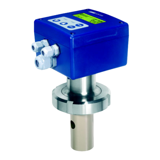
2 General Design of the JUMO CTI-750 Examples Version: Version: Transmitter Transmitter with combined with separate sensor, conductivity sensor, Type 202756/xx... Type 202756/xx... (1) Transmitter (4) Inductive conductivity sensor (2) Process connection (5) With or without graphics LC display (3) Temperature probe... -
Page 8: Inductive Conductivity Measurement
In this case, the setup program is needed for programming. The JUMO CTI-750 is available either as a combined unit (transmitter and measuring cell together in one unit) or as a split version (transmitter and cell connected by cable). -
Page 9: Function
3 Inductive conductivity measurement Function of the The JUMO CTI-750 transmitter has been designed for use on site. A rugged transmitter housing protects the electronics and the electrical connections from corrosive environmental conditions (enclosure IP67). As standard, the device has one analog signal output each for conductivity/concentration and temperature respectively. -
Page 10: Instrument Identification
4 Instrument identification Nameplate on the transmitter JUMO GmbH & Co. KG Fulda, Germany www.jumo.net JUMO CTI-750 Typ: 202756/15-607-0000-82/000 VARTN: 20/00445843 F-Nr.: 00909467 01 0 0517 0001 DC 19...31 V on the connecting cable (only with F-Nr.: 00909467 01 0 0517 0001... -
Page 11: Type Designation
4 Instrument identification Type designation JUMO CTI-750 as “Head-mounted transmitter” (1) Basic type 202756 Inductive transmitter/switching device for conductivity/concentration and temperature: JUMO CTI-750 (2) Basic type extensions head-mounted transmitter without display/keypad head-mounted transmitter with display/keypad (3) Process connection screwed pipe connection DN50, DIN 11 851 (MK DN50, milk cone) clamp 2 1/2"... -
Page 12: Jumo Cti-750 As "Transmitter With Separate Sensor
4 Instrument identification JUMO CTI-750 as “Transmitter with separate sensor” (1) Basic type 202756 Inductive transmitter/switching device for conductivity/concentration and temperature: JUMO CTI-750 (2) Basic type extensions replacement transmitter without display/keypad (without sensor) replacement transmitter with display/keypad (without sensor) transmitter without display/keypad... -
Page 13: Instrument Description
5 Instrument description Technical data for transmitter 5.1.1 General A/D converter resolution: 15-bit sampling time: 500 msec = 2 measurements/sec Supply standard: 19 — 31 V DC (24 V DC nominal), with reverse-polarity protection ripple: < 5% ≤ 3 W power consumption with display: power consumption without display: ≤... - Page 14 5 Instrument description 5.1.2 Conductivity/concentration transmitter Concentration - NaOH (caustic soda) measurement 0 — 15 % by weight or 25 — 50 % by weight (implemented in - HNO (nitric acid); check chemical resistance of the sensor ! the device 0 —...
-
Page 15: Temperature Compensation
5 Instrument description 5.1.3 Temperature transmitter Temperature manually 0.0 to 25.0 to 150°C/°F acquisition automatically Temperature 0 to 150°C/°F measurement range Characteristic linear ≤ 0.5% of range Accuracy ≤ 0.1%/°C Ambient temperature error Output signal 0 — 10 V / 10 — 0 V 2 —... - Page 16 5 Instrument description 5.1.5 Sensor Material PEEK (polyether ether ketone) or PVDF (polyvinylidene fluoride) Note: Temperature, pressure and sample medium affect the operating life of the cell Temperature of 120°C max. the sample briefly 140°C (sterilization) medium Pressure 10 bar max. Tolerance Measurement range (in % of range...
-
Page 17: Mounting
“Mounting factor” parameter. For submerged operation in basins, a location must be chosen that is representative of the typical conductivity or concentration. Operating The JUMO CTI-750 can be mounted in any position. position Screwing in and The cable must not be twisted! unscrewing the Avoid putting tension on the cable. -
Page 18: Dimensions / Process Connections For Head Transmitter
6 Mounting Dimensions / Process connections for head transmitter Installation variations Version with Version with process connection -607 process connection -617 MK DN50 clamp 2 " (retaining clip not included in delivery) Version with Version with process connection -686 process connection -690 VARIVENT ®... -
Page 19: Jumo Cti-750 With Separate Sensor (Split Version)
6 Mounting JUMO CTI-750 with separate sensor (split version) Transmitter head Drilling jig for wall-mounting... - Page 20 6 Mounting Sensor component Split version with Split version with process connection -617 process connection -607 clamp 2 " MK DN50 (retaining clip not (union nut not included in delivery) included in delivery) M12 socket (PBT / PA) Cable gland M16 (PA) Process connection 686 ®...
-
Page 21: Mounting Examples
6 Mounting Mounting examples Weld-on threaded pipe adaptor DN50, DIN 11 851 (matching part for process connection -607) Sales No. 20/00085020... - Page 22 6 Mounting 6.4.1 Pipe-mounting kit The screws (1) M5 x 30 are used with pipe diameters from 30 to 40 mm. The screws (2) M5 x 40 are used with pipe diameters from 40 to 50 mm. The pipe-mounting kit is also suitable for horizontal pipes.
-
Page 23: Installation
7 Installation The electrical connection must only be carried out by properly qualified personnel! The choice of cable, the installation and the electrical connection must conform to the requirements of VDE 0100 “Regulations on the Installation of Power Circuits with Nominal Voltages below 1000 V” or the appropriate local regulations. -
Page 24: General
7 Installation General Opening the operating unit It is only necessary to open the housing for devices with cable glands. Devices with M12 plug/socket connectors should not be opened! Remove four screws (1) and take off the cover Connecting up the cables To connect the single conductors, pull off the pluggable screw terminals (1) in the operating unit. - Page 25 7 Installation Wiring For devices with a separate sensor (type code extensions (2) /60 or /65), the transmitter and detached sensor are matched to one another at the factory! When connecting the components, please note that the serial number of the external sensor (marked on the label attached to the connecting cable) must match the serial number marked on the nameplate of the transmitter! Caution:...
- Page 26 7 Installation Connections Connection Screw Conn./pin for the terminals transmitter Supply standard: 1 L+ I / 1 supply voltage 2 L- I / 2 19 — 31 V DC (with reverse-polarity protection) with extra code 844: 24 V AC Outputs Analog signal output: I / 3 Conductivity/concentration...
-
Page 27: Setup Program
8 Setup program Function Configurable The setup program, which is available as an option, can be used for easy parameters adaptation of the transmitter to specific requirements. - Setting the measurement range and the range limits. - Setting the response of the output to an out-of-range signal. - Setting the functions of the switched outputs K1 and K2. -
Page 28: Commissioning
9 Commissioning The transmitter has been tested in the factory for fault-free functioning, and is delivered ready for operation. Head-mounted transmitter or transmitter with separate sensor Mounting the instrument, see “Mounting”, page 17. Connecting the instrument, see “Installation”, page 23. For devices with a separate sensor (type code extensions (2) /60 or /65), the transmitter and detached sensor are matched to one another at the factory! When connecting the components, please note that the serial number of the... -
Page 29: Operation
10 Operation 10.1 Controls JUMO CTI-750 without LC display JUMO CTI-750 with LC display (1) Graphics LC display, (5) LEDs K1 and K2 show the back-lit states of the switched outputs. In normal operation, the LED confirm entries/select menu lights up if the corresponding EXIT output is active. - Page 30 10 Operation LC display (11) (10) Output K1 is active Output mode - Hand (manual operation) Output K2 is active - Hold (hold operation) Binary input 1 is Conductivity/concentration activated measurement Binary input 2 is Unit for conductivity/ activated concentration measurement Keypad is inhibited (10) Temperature of the medium...
-
Page 31: Principle Of Operation
10 Operation 10.2 Principle of operation Operation in levels... -
Page 32: Measurement Mode
10 Operation 10.3 Measurement mode Representation In measurement mode, the conductivity is shown (compensated for the reference temperature) or the concentration and temperature of the medium being measured. MEASUREMENT -> Measurement mode 20.5°C -> Temperature of the sample medium 203 mS/cm -> Conductivity of the medium (compensated for the reference/comparison temperature –... - Page 33 10 Operation 10.4.1 CONDUCTIVITY IN (conductivity input) RANGE 1 — 4 0 — 500 µS/cm 0 — 1000 µS/cm 0 — 2000 µS/cm 0 — 5000 µS/cm 0 — 10 mS/cm 0 — 20 mS/cm 0 — 50 mS/cm 0 — 100 mS/cm 0 —...
- Page 34 10 Operation MOUNTING FACTOR 80.0 — 100.0 — 120% If it is not possible to achieve the minimum clearance of 20 mm between the sensor and the outer wall, then a limited compensation can be made through this parameter. CONC. MEAS. TYPE NO FUNCTION NaOH HNO3...
- Page 35 10 Operation 10.4.2 CONDUCTIVITY OUT (conductivity output) SIGNAL TYPE 0 — 20 mA 4 — 20 mA 20 — 0 mA 20 — 4 mA 0 — 10 V 2 — 10 V 10 — 0 V 10 — 2 V SCALING START 1 —...
- Page 36 10 Operation 10.4.3 TEMPERATURE IN DIMENS. UNIT °C °F MEAS. MODE SENSOR MANUAL MANUAL VALUE 0.0 to 25.0 to 150°C OFFSET -15.0 to 0.0 to 15.0°C FILTER TIME 00:00:00 — 00:00:01 — 00:00:25 H:M:S 10.4.4 TEMPERATURE OUT SIGNAL TYPE 0 — 20 mA 4 —...
- Page 37 10 Operation DURING CALIBRATION MOVING FROZEN SAFE VALUE SAFE VALUE 0.0 — 4.0 — 22.0 mA (depending on the signal type) 0 — 10.7 V MANUAL MODE MAN. VALUE 0.0 — 4.0 — 22.0 mA (depending on the signal type) 0 —...
- Page 38 10 Operation LK1 alarm window LK2 alarm window Pulse contact Pulse contact Trigger condition longer than Trigger condition shorter than pulse duration pulse duration LIMIT 0.0 — 999.0 (depending on the function, see above) HYSTERESIS 0.0 — 1.0 — 999.0 (depending on the function, see above) SPACING 0.0 —...
- Page 39 10 Operation ON-DELAY 00:00:00 — 01:00:00 H:M:S OFF-DELAY 00:00:00 — 01:00:00 H:M:S PULSE DURATION 00:00:00 — 01:00:00 H:M:S (see above: “Function, Pulse contact”) 10.4.6 BINARY INPUT 1 and BINARY INPUT 2 FUNCTION NO FUNCTION HOLD/LOCK KEY RANGE/TEMPCO. DILUTION Setting parameters Binary input 1 Binary input 2 Range/...
-
Page 40: Administrator Level
10 Operation 10.4.8 INSTRUMENT DATA LANGUAGE GERMAN ENGLISH FRENCH SPANISH POLISH SWEDISH ITALIAN PORTUGUESE Entering the password 7485 in the administrator level will reset the operating language to English. CONTRAST 0 — 6 — 11 LIGHTING IF OPERATED (approx. 50 sec after the last key operation: the lighting will be switched off) LCD INVERSE 10.5 Administrator level... - Page 41 10 Operation Levels within administrator level 10.5.1 Parameter level The administrator can edit all parameters for the operator level in this level. The structure “Parameter level” within the administrator level is identical to the operator level, see “Operator level”, page 32 and the following. 10.5.2 Enable level In this level, the administrator can define which parameters can be altered or edited by the operator in the operator level.
-
Page 42: Calibration Level
10.6.2 TEMPCO LINEAR (linear temperature coefficient) If this function has been enabled by the administrator, then the operator can calibrate the JUMO CTI-750 for liquids with a linear temperature coefficient; see “Linear temperature coefficient (ALPHA)”, page 48. 10.6.3 TEMPCOMP NON-LIN. (non-linear temperature coefficient) -
Page 43: Dilution Function
- The dilution function is only available in the “Conductivity measurement” with the mode – not for concentration measurement. JUMO CTI-750 - When the dilution function is activated, all the parameters that are irrelevant for this function are switched off. - Page 44 10 Operation - The dilution factor can be adjusted through binary input 1 over a range 1 — 50% below the limit value. The preset value is 10% below the limit. 10.7.1 Stop dilution All the parameters are system-dependent, and must be adjusted to suit system requirements.
- Page 45 10 Operation Use the key to select DILUTION; use the key to confirm the selection. Change to the operator level, using the key. EXIT Use the key to select DILUTION. Confirm the selection with the key. Use the key to set the dilution factor in the range from 1 —...
- Page 46 10 Operation Use the key to select LOCK TIME; use the key to confirm the selection. Set the lock time with the key in the range from 0:00:00 — 00:01:00— 18:00:00 H:M:S. Confirm the setting with the key. If there is an interruption in the supply voltage during dilution, the function will be canceled.
-
Page 47: Calibration
In order to meet enhanced demands for precision, the cell constant must first be calibrated. Requirements - The supply voltage for the JUMO CTI-750 must be present. see Chapter 7 “Installation”, page 23ff. - The sensor must be connected to the transmitter (applies to the split version). -
Page 48: Calibrating The Temp. Coefficient Of The Sample Solution
Press The relative cell constant calculated by the JUMO CTI-750 will be displayed. To accept the relative cell constant that has been determined -> press the key for at least 3 seconds or to reject the value ->... - Page 49 11 Calibration see Chapter 7 “Installation”, page 23ff. - The sensor must be connected to the transmitter (applies to the split version). - The transmitter is in the measurement mode. Immerse the conductivity sensor in a sample of the solution to be measured.
- Page 50 10°C/min for a JUMO CTI-750 with exposed temperature sensor, 1°C/min for a JUMO CTI-750 with an internal temperature sensor. As soon as one of the target temperatures has been reached, its display becomes static (no longer blinking).
- Page 51 11.3.2 Non-linear temperature coefficient (ALPHA) General Since the temperature coefficient of some media is not constant over a sizeable temperature range, the JUMO CTI-750 provides the option of subdividing a temperature range (T to T ) into 5 sections. A different TC Start value can be used for compensation in each of these range sections.
- Page 52 The temperature range between the start and end calibration temperatures is subdivided into 5 sections of equal size. on the The temperature range must be larger than 20°C, and cover the reference JUMO CTI-750 temperature. Example: Reference temperature 25°C, start temperature 18°C and end temperature 50°C.
- Page 53 - 01°C / min for an internal temperature sensor. Requirements - The supply voltage for the JUMO CTI-750 must be present. see Chapter 7 “Installation”, page 23ff. - The sensor must be connected to the transmitter (for the split version).
- Page 54 11 Calibration Use the key to enter the start temperature; confirm with the key. The start temperature must be lower than the reference temperature (25.0°C). Use the key to enter the end temperature; confirm with the key. The end temperature must be at least 20°C above the start temperature.
- Page 55 Warm up the sample medium until is it above the temperature that is blinking. Repeat the procedure as often as required, until the JUMO CTI-750 has determined all 6 temperature coefficients. The LC display now shows the derived temperature coefficients in %/°C.
-
Page 56: Maintenance
12 Maintenance 12.1 Cleaning the conductivity sensor Do not use solvents. Hard-to-remove crusts and deposits can be softened and removed with dilute hydrochloric acid. Observe the safety regulations! Deposits Deposits on the sensor section can be removed with a soft brush (e.g. a bottle brush). -
Page 57: Eliminating Faults And Malfunctions
13 Eliminating faults and malfunctions Possible Problem Possible cause Measures errors No measurement display Supply voltage Check supply voltage, missing also check terminals signal output Measurement display Sensor not immersed in Top up the reservoir 000 or medium, signal output 0% reservoir level (e.g. - Page 58 For display values up to 20 mS, the loop must have 1 turn. For display values above 50 mS, the loop must have 3 turns. The cell constant of the JUMO CTI-750 depends on the style. The T-shaped measuring cell has a cell constant of 6.80 1/cm.
- Page 59 13 Eliminating faults and malfunctions Example 1 The JUMO CTI-750 with a T-shaped measuring cell is to show 20 mS: ·6.80 1/cm Ω = 340 20·10 S/cm To obtain a display of 20 mS/cm, the resistance loop (with 1 turn) must have a resistance of 340 Ohm.
- Page 60 13 Eliminating faults and malfunctions Precalculated The display value 0 is obtained if the sensor is dry and without a conductive values deposit, and has no resistance loop fitted. Style / cell constant Material: PEEK Material: PEEK K = 6.80 1/cm K = 6.50 1/cm Number of Cell constant...
- Page 61 Test Calculate the test resistance. sequence Connect up the JUMO CTI-750, see Chapter 7 “Installation”, page 23. Select the corresponding measurement range, see Chapter 10.4.1 “CONDUCTIVITY IN (conductivity input)”, page 33 -> RANGE 1 — 4 Set TC to 0%/°C, see Chapter 10.4.1 “CONDUCTIVITY IN (conductivity input)”, page 33 ->...
- Page 62 Prepare the conductivity test solution in a container of adequate size. sequence Connect up the JUMO CTI-750, see Chapter 7 “Installation”, page 23. Select the range appropriate to the conductivity test solution, see Chapter 10.4.1 “CONDUCTIVITY IN (conductivity input)”, page 33 -> RANGE 1 — 4 Set TC to 0%/°C, see Chapter 10.4.1 “CONDUCTIVITY IN (conductivity...
-
Page 63: Appendix
14 Appendix 14.1 Before configuration If a number of instrument parameters have to be modified in the instrument, then it is advisable to note them in the table below, and then modify these parameters in the sequence given. The following list shows the maximum number of parameters that can be altered. - Page 64 14 Appendix Parameter Selection / value range see page Factory setting setting Scaling start 0 — 90% = 4 mA (e.g.) of range span Scaling end 100 — 10% = 20 mA (e.g.) of range span During alarm high safe value During calibration moving frozen...
- Page 65 14 Appendix Parameter Selection / value range see page Factory setting setting During calibration moving frozen safe value Safe value 0.0 — 4.0 — 22.0 mA Manual mode Manual value 0.0 — 4.0 — 22.0 mA Binary output 1 or binary output 2 Function no function conductivity MIN contact...
- Page 66 14 Appendix Parameter Selection / value range see page Factory setting setting Language German English French Spanish Polish Swedish Italian Portuguese Contrast 0 — 6 — 11 Lighting during operation LCD inverse...
Need help?
Do you have a question about the CTI-750 and is the answer not in the manual?
Questions and answers