
Related Manuals for JUMO ecoTRANS Lf 03


Summary of Contents for JUMO ecoTRANS Lf 03
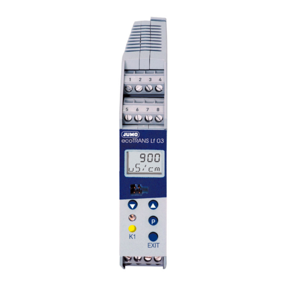
- Page 1 Lf 03 Transmitter / Switching Device for Conductivity Type 202732 B 20.2732.0 Operating Manual 02.05/00429233...
-
Page 3: Table Of Contents
Notes ......... . 5 Identifying the instrument version . - Page 4 Display and LED messages ..... . . 59 12.1 Operating states of the JUMO ecoTrans Lf 03 ....59 12.2 Underrange .
-
Page 5: Notes
1 Notes All necessary settings are described in this Operating Manual. However, if any difficulties should still arise during start-up, please do not carry out any manipulations on the unit. You could endanger your rights under the instrument warranty! Please contact the nearest subsidiary or the head office in such a case. -
Page 6: Identifying The Instrument Version
The supply voltage must correspond to the voltage given on the nameplate. 2.1 Type designation (1) Basic type 202732 JUMO ecoTRANS Lf 03, Microprocessor transmitter / switching device for conductivity (freely programmable ranges) (2) Output I (conductivity / resistivity) analog signal output, freely programmable... -
Page 7: Installation
3 Installation °C £ 75 4 Electrical connection The choice of cable, the installation, the fusing and the electrical connection must conform to the requirements of VDE 0100 “Regulations on the Installation of Power Circuits with Nominal Voltages below 1000 V” or the appropriate local regulations. The electrical connection must only be carried out by qualified personnel. - Page 8 The load circuit must be fused for the maximum relay current, in order to prevent the output relay contacts becoming welded in the event of a short circuit. Do not connect any additional loads to the screw terminals for the supply of the instrument. Any electrical connection other than that specified in the connection diagram may result in the destruction of the instrument.
- Page 9 Terminal assignment EXIT Outputs Terminals Symbol Analog signal output for conductivity (electrically isolated) Analog signal output for temperature (electrically isolated)
- Page 10 common Relay n.c. (break) n.o. (make) Ö Open-collector output 1 (electrically isolated) Open-collector output 2 (electrically isolated) Measurement Terminals Symbol inputs Conductivity outer electrode, cell on coaxial cells inner electrode, on coaxial cells Resistance temperature sensor thermometer in 2-wire circuit Resistance temperature sensor thermometer...
- Page 11 Supply Terminals Symbol Supply voltage (with reverse- polarity protection) Connection of the conductivity cell Conductivity cell JUMO (JUMO types) ecoTRANS Lf 03 Plug-in head Attached cable Outer electrode white Inner electrode brown Temperature yellow compensation green...
-
Page 12: Commissioning
Note After initializing the controller, the output signal is 0 V or 0 mA. The logic outputs or relays are in the quiescent state (inactive). After approx. 2 sec, the JUMO ecoTRANS Lf 03 operates according to its configuration. -
Page 13: Setting / Altering The Instrument Functions
6 Setting / altering the instrument functions Alterations can be carried out in the setup program or from the keys of the JUMO ecoTRANS Lf 03. 6.1 Actual-value display The actual value is displayed either in the - static mode or in the... -
Page 14: Operation
6.2 Operation The operation of the instrument is arranged on levels. The access to all levels (exception: operator level) is protected by different codes At the operator level (USER), all parameters can be viewed or altered in accordance with the user rights (see enabling level). - Page 15 - In order to alter a parameter, it must be enabled at the enabling level (set from “rEAd” to “Edit”). - Press the UP or DOWN key to increase or decrease the value. - Accept the value by pressing the P key. - Use the EXIT key to cancel the entry and change to the next- higher level.
-
Page 16: Level Selection
6.4 Level selection see Chapter 6.5 “The operator level (USER)”, page 17 see Chapter 6.6 “The administrator level (ADMIN)”, page 18 see Chapter 6.7 “The enabling level (RIGHT)”, page 19 see Chapter 6.8 “The calibration level (CALIB)”, page 20 or time-out (automatic return after 60 sec without operator action) -
Page 17: The Operator Level (User)
6.5 The operator level (USER) -
Page 18: The Administrator Level (Admin)
6.6 The administrator level (ADMIN) -
Page 19: The Enabling Level (Right)
6.7 The enabling level (RIGHT) Parameters at the operator level (USER) Value is shown can be altered EDIT READ... -
Page 20: The Calibration Level (Calib)
6.8 The calibration level (CALIB) see Chapter 8 “Calibration”, page 41. see Chapter 8.4 “Calibrating the temperature coefficient using automatic temperature measurement”, page 44 or Chapter 8.5 “Calibrating temperature coefficient using manual temperature entry”, page 47. see Chapter 8.6 “Calibrating the relative cell constant”, page 49. The time-out function is not active during calibration! -
Page 21: Setting Ranges
7 Setting ranges 0 — 1 µS to 0 — 200 mS, depending on the cell constant Unit 0 = S/cm 1 = mho/cm Cell Range constant 0 – 1.000 µS/cm 0 – 1.000 µmho/cm 0 – 2.00 µS/cm 0 – 2.00 µmho/cm 0.01 0 –... - Page 22 Unit 2 = kΩ*cm 3 = MΩ*cm Cell Range constant 1000 – 9999 kΩ*cm 1.00 – 99.99 MΩ*cm 500 – 9999 kΩ*cm 0.50 – 50.00 MΩ*cm 0.01 200 – 9999 kΩ*cm 0.20 – 20.00 MΩ*cm 50 – 2500 kΩ*cm 0.05 – 2.50 MΩ*cm 200 –...
-
Page 23: Configurable Parameters
8 Configurable parameters... -
Page 41: Calibration
8 Calibration 8.1 General The cell constants of conductivity cells stray somewhat depending on the type and additionally change during operation (due to deposits such as lime, or as a result of wear). This results in a change of the output signal from the cell. It is therefore necessary that the user is able to compensate for the deviations of the cell constant from the nominal value, either by manual entry or an automatic calibration of the cell constant K... -
Page 42: Activating The Calibration Mode
8.2 Activating the calibration mode The setup interface and the measurement inputs for conductivity and temperature are not electrically isolated. This means that, in unfavorable conditions, equalizing currents may flow when the PC interface is connected. These equalizing currents may result in damage to the devices connected. -
Page 43: Selecting The Calibration Procedure
or Chapter 6.8 “The calibration level (CALIB)”, page 20 The code for enabling the calibration mode is: Start the calibration in the setup program. 8.3 Selecting the calibration procedure Calibrating the temperature coefficient Confirm selection with continue with Chapter 8.4 “Calibrating the temperature coefficient using automatic temperature measurement”, page 44 Chapter 8.5 “Calibrating the temperature coefficient using manual temperature entry”, page 47... -
Page 44: Calibrating The Temperature Coefficient Using Automatic Temperature Measurement
8.4 Calibrating the temperature coefficient using automatic temperature measurement Note During calibration, the reference temperature and the working temperature can be approached in any sequence. Immerse the conductivity cell and the temperature sensor in the medium to be measured. blinks The currently measured temperature is displayed. - Page 45 - the current value can be accepted immediately by pressing the key (for less than 1 second). - When the first calibration point has been accepted, the lower line will show NEXT. Press the key. Temper the medium to be measured to the working temperature. - The LC display shows the temperature in the upper line, and the uncompensated conductivity in the line below.
- Page 46 discard it by pressing the EXIT key. - The instrument will now show the currently present conductivity (the actual value). Note Possible errors: 2 identical calibration points or temperature coefficient larger than 5.5% - The instrument indicates an error. After pressing the key or EXIT, the selected calibration procedure is shown (see Chapter 8.3 “Selecting the calibration procedure”, page 43).
-
Page 47: Calibrating The Temperature Coefficient Using Manual Temperature Entry
8.5 Calibrating the temperature coefficient using manual temperature entry Note During calibration, the reference temperature and the working temperature can be approached in any sequence. Immerse the conductivity cell and the temperature sensor in the medium to be measured. blinks WORK.T shows you that the working temperature that will be used later on has to be entered. - Page 48 - When the first calibration point has been accepted, NEXT will be shown in the bottom line. Press Temper the medium to the working temperature. - The uncompensated conductivity is shown in the bottom line in the LC display. The current value can be accepted immediately by pressing (for less than 1 second).
-
Page 49: Calibrating The Relative Cell Constant
Note Possible errors: 2 identical calibration points or temperature coefficient larger than 5.5% - The instrument indicates an error. After pressing the key or EXIT, the selected calibration procedure is shown. 8.6 Calibrating the relative cell constant General Because of manufacturing variations, each conductivity cell has a real cell constant which deviates slightly from the ideal nominal cell constant. - Page 50 Immerse the conductivity cell into a solution with a known conductivity. approx. 3 sec - The uncompensated conductivity of the reference solution (actual value) and CAL.C are shown in alternation. As soon as the value displayed is stable: press (for less than 1 second).
- Page 51 outside 20 — 500%. < 20% Conductivity = 0 > 500% The instrument indicates an error. After pressing or EXIT, the selected calibration procedure is shown (see Chapter 8.3 “Selecting the calibration procedure”, page 43). The latest valid measurement continues to be active.
-
Page 52: Analog Output
9 Analog output The analog outputs are configured at the operator level (USER) or the administrator level (ADMIN) in CO.OUT (conductivity output) TE.OUT (temperature output) see Chapter 6.5 “The operator level (USER)”, page 17. 9.1 Response during calibration You can choose between “following” or “unchanged” (constant). 9.2 Response of the output signal in fault condition Depending on the configuration, the output signal can adopt the LOW or HIGH condition in the event of a fault. -
Page 53: Response Of The Output Signal On Leaving The Scaling Range
10 — 2 V 1.8 V 9.4 Manual operation of the analog output The JUMO ecoTRANS Lf 03 can output a constant analog signal, for test purposes or commissioning, see also Chapter 10.2 “Manual operation of the relay outputs”, page 54. -
Page 54: Relay Output / Open-Collector
10 Relay output / open-collector 10.1 Response of the relay Depending on the setting, the JUMO ecoTRANS Lf 03 monitors a limit, similar to a limit comparator (LK), as a MAX LK or MIN LK. The hysteresis is asymmetric with respect to the limit. - Page 55 “-” means the corresponding output is not in manual mode. 1st place: analog output for conductivity 2nd place: analog output for temperature 3rd place: logic output 1 4th place: logic output 2 (if available) In the example above, the analog temperature output is in manual mode, all other outputs are not.
-
Page 56: Response Of The Relay During Calibration
10.3 Response of the relay during calibration The parameter USER / BIN.1 (or BIN.2) / CAL.1 (or CAL.2) can be used to set the relay response to: relay inactive relay active relay unchanged (during calibration, the relay remains at the status that was valid before the start of the calibration) 10.4 Pulse function of the relay output The limit comparator is reset after an adjustable pulse time. -
Page 57: The Usp Contact (For High-Purity Water)
USP <645>. If, at a given temperature, the conductivity of the water is higher than specified in the USP table, the USP contact of the JUMO ecoTRANS Lf 03 will switch. The limits are defined in steps; at 8°C, for example, a value of 5°C is applied. -
Page 58: Usp Pre-Alarm
If the conductivity exceeds the value for the corresponding temperature, the configured contact will switch. 11.1 USP pre-alarm The USP pre-alarm switches before the water quality reaches the set limit. The parameter: USER / BIN.1 / S.USP1 (0 — 100) can be used to define a margin between pre-alarm and USP limit, as a percentage value referred to the active limit. -
Page 59: Display And Led Messages
12 Display and LED messages 12.1 Operating states of the JUMO ecoTrans Lf 03 Two LEDs indicate the operating states Device status LED red (top) LED yellow (bottom) Normal operation on, when LK1 is active Error blinks on, when LK1 is... -
Page 60: Short Circuit
12.5 Short circuit 12.6 Initialization of dependent parameters After altering one parameter, other dependent parameters are altered automatically. Please check all dependent parameters! 12.7 Calibration timer has run down In accordance with the specifications (of the plant manufacturer, for example), calibration of the cell constant and/or of the temperature coefficient should be carried out. -
Page 61: Operation Via Setup Interface
– Windows 2000 ® – Windows XP ® – Windows NT 4.0 or higher JUMO ecoTRANS Lf 03 PC interface cable EXIT JUMO PC setup software multilingual D / GB / F Caution The setup interface and the measurement inputs for conductivity and temperature are not electrically isolated. -
Page 62: Operation Through Setup
A double-click on the text will call up the corresponding editing window. Customized linearization for the temperature probe A table for 30 value pairs can be used to adapt any temperature probe to the temperature input of the JUMO ecoTRANS Lf 03. -
Page 63: Technical Data
14 Technical data Conductivity input Electrolytic conductivity cells with the cell constants 0.01; 0.1; 1.0; 3.0; 10.0 (2-electrode principle). The cell constant can be adjusted over the range 20 — 500%. Lead compensation, conductivity input The effect of long cables can be compensated on ranges larger than about 20 mS/cm by entering the lead resistance, within the range from 0.00 to 99.99 Ω. - Page 64 A parallel resistor with 8.2 kΩ is required! - NTC 2K25 measuring range: 0 to +150°C resistance: 2.25 kΩ at 25°C A parallel resistor with 8.2 kΩ is required! - KTY11-6 measuring range: -10 to +150°C resistance: 2 kΩ at 25°C - All temperature probes can be connected in 2-, 3- or 4-wire circuit.
- Page 65 Open-collector output contact rating: 100 mA, 35 V DC with resistive load, voltage drop in the switched state ≤ 1.2V, not short-circuit proof A/D converter resolution 14 bit Sampling time 500 msec = 2 measurements per second Ambient temperature error ≤...
-
Page 66: Environment / Waste Disposal
DIN rail mounting: PC (polycarbonate) Mounting on a 35 x 7.5 mm DIN rail to EN 60 715 Operating position unrestricted Weight approx. 150g 15 Environment / waste disposal Faulty devices can be returned to JUMO for proper disposal.
Need help?
Do you have a question about the ecoTRANS Lf 03 and is the answer not in the manual?
Questions and answers