
Related Manuals for JUMO DELOS SI


Summary of Contents for JUMO DELOS SI
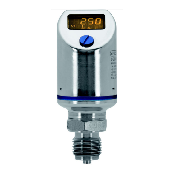
- Page 1 JUMO DELOS SI Precision pressure transmitter with switching contacts and display Operating Manual 40505200T90Z003K000 V2.00/EN/00526948...
-
Page 3: Table Of Contents
Content Safety information ................5 Warning symbol ....................5 Note symbols .......................5 Description ..................7 General ........................7 Identifying the instrument version ..........9 Nameplate ......................9 Block diagram ......................9 Order details .......................10 Accessories ......................12 Software ......................12 Electrical connection ..............13 Installation instructions ..................13 Color assignment of M12 x 1 round plug ............13 Terminal assignment for output 470 ..............14 Terminal assignment for output 471 ..............14... - Page 4 Content Getting started ....................29 Unlocking the instrument (code entry) ...............30 Cancel operation ....................31 Selecting the unit of the measured value (Uni.P) ..........31 Setting the zero point (offset) (Off.P) ..............34 Setting the filter time constant (damping) (DamP) ..........35 Setting the output signal (S.TyP) ...............35 Setting scaling ....................36 Setting the error signal (S.Err) ................39 7.10...
-
Page 5: Safety Information
1 Safety information Warning symbol DANGER! This symbol indicates that personal unjury caused by electrical shock may occur, if the respective precautionary measures are not carried out. CAUTION! This symbol in connection with the signal word indicates that damage to assets or data loss will occur if the respective precautionary measures are not taken. - Page 6 1 Safety information...
-
Page 7: Description
2 Description General • Depending on its design, the instrument measures relative or absolute pressure in liquid and gaseous media. • The pressure is displayed digitally. • Depending on the design, the following outputs are available: - 1 PNP switching output - 2 PNP switching outputs - 1 PNP switching output + 1 analog output 4 to 20 mA - 1 PNP switching output + 1 analog output 0 to 20 mA... - Page 8 2 Description...
-
Page 9: Identifying The Instrument Version
3 Identifying the instrument version Nameplate on the pressure switch Made in Germany www.jumo.net DELOS SI 405052/000 TN 12345678 0...250 mbar DC 12...30 V 4...20 mA/OC: 250 mA F.-Nr.: 001234567801008350123 Type Output signal Sales no. Manufacturing number Measuring range Date of manufacture... -
Page 10: Order Details
3 Identifying the instrument version Order details (1) Basic type 405052/000 JUMO DELOS SI – Precision pressure transmitter with switching contacts and display 405052/004 JUMO DELOS SI – Precision pressure transmitter with switching contacts and display for increased measuring material temperatures upt to 200 °C 405052/999 JUMO DELOS SI –... - Page 11 This JUMO product is licensed under United States and Canadian patents. Purchasers of the JUMO product outs- ide of the United States and Canada should advise JUMO of any planned sales of products incorporating the JUMO product into the United States and Canada.
-
Page 12: Accessories
3 Identifying the instrument version Accessories Article Part no. PC interface cable including USB/TTL converter 00456352 Y transmitter cable, 5 pole 00507861 Combination tool 00526614 Cable connector, straight, 4 pole, M12 × 1, 2 m PVC cable 00404585 Cable connector, angled, 4 pole, M12 × 1, 2 m PVC cable 00409334 Cable socket, 5 pole, M12 ×... -
Page 13: Electrical Connection
4 Electrical connection Installation instructions DANGER! The electrical connection must only be performed by qualified personnel! The load circuits must be fused for the maximum load currents in each case to prevent the instrument from being destroyed. Electromagnetic compatibility meets the requirements of EN 61326. No other consumers can be connected to the voltage supply of the instrument. -
Page 14: Terminal Assignment For Output 470
4 Electrical connection Terminal assignment for output 470 One PNP switching output Voltage supply 1 L+ DC 12 to 30 V 3 L- Output 4 K1 Highside Open Collector maximum 0.25 A Interface Terminal assignment for output 471 Two PNP switching outputs Voltage supply 1 L+ DC 12 to 30 V... -
Page 15: Terminal Assignment For Outputs 475, 476, And 477
4 Electrical connection Terminal assignment for outputs 475, 476, and 477 One PNP switching output + one analog output Voltage supply 1 L+ DC 12 to 30 V 3 L- Output 4 K1 Highside Open Collector maximum 0.25 A 2 Analog 0(4) to 20 mA/0 to 10 V Interface... - Page 16 4 Electrical connection...
-
Page 17: Mounting
5 Mounting General information CAUTION! The compatibility of the instrument with the measuring medium must be tested, see chapter 11 „Technical data“, page 57. Mounting location • Find a location that ensures easy accessibility for later operation. • The fastening must be secure and must ensure low vibration for the instrument. •... - Page 18 5 Mounting 5.1.1 Rotating the display The display image can be rotated 180° in the software, siehe „Display position“, page 27. This may make it easier to read when the instrument is installed overhead, for example. 5.1.2 Rotating the housing The instrument housing can be rotated a maximum of 320°...
-
Page 19: Dimensions Of Electronic Pressure Switches
5 Mounting Dimensions of electronic pressure switches Type 405052/000-... Typ 405052/004-... for increased medium temperature Ø 42 NOTE! The overall height is 40 mm greater for instruments with basic type extension 004 (for increased medium temperature up to 200 °C). See drawing... - Page 20 5 Mounting 5.2.1 Process connections, not front-flush G 1/2 1/4-18 NPT 1/4-18 NPT 11.07 G 1/2 G 1/4 G 1/2 G 1/4 G 1/2 Profile seal DN G 1/4 Profile seal DN G 1/2 5.2.2 Process connections, front-flush G 3/4 G 3/4 with 2-way seal G 3/4 Ø...
- Page 21 5 Mounting 603 to 607 G 1 with 2-way seal Taper socket with union nut Ø 30 Profile seal DN G 1 O-ring 26.7 × 1.78 612 to 616 Clamp Process connection Ø D Ø D Ø D Ø D 36.5 RD 44 ×...
- Page 22 Tank connection with grooved union nut Ø 45 Ø 35 ø19 ø26 ø40 R 52 × 1/6 Ø 55 Ø 63 O-ring 29.82 × 2.62 JUMO PEKA NOTE! For detailed information about this process connection system, see data sheet 409711.
-
Page 23: Operation
6 Operation Controls Protective screw Hexagon socket • Unscrew the protective screw (1). • "Turn/push" the control element (2) with the enclosed combination tool (or a 0.5 × 3 screwdriver). LC display 6.2.1 Measurement mode Normal display Example: The display is lit yellow. -
Page 24: Levels
6 Operation 6.2.2 Settingmode Example: The display is lit red. Operation Press the combination tool less than 1 second ( 1 s) Continue Press the combination tool less than 1 second ( 1 s) Yes (accept) Press the combination tool more than 3 seconds ( 3 s) No (Cancel) No activity for more than 60 seconds ( ... -
Page 25: Parameter
6 Operation Parameter 6.4.1 Input Parameter Display Setting range Pressure unit mbar Note: The units kPa and mbar cannot be configured for all mea- suring ranges. Offset -20.00 to 0.00 to +20.00 % of the measuring range (zero-point correction) Note: Automatic offset correction see chapter 7.5 "Setting the zero point (offset) (Off.P)", page 34. - Page 26 6 Operation 6.4.3 Binary output 1 Parameter Display Setting range Switching function Hysteresis, make contact (for switching output only) Hysteresis, break contact Window, make contact Window, break contact see chapter 7.10 "Setting the switching function (B.Fct)", page 40. Switching point 0.00 to 100.00 % of nominal measuring range (for switching output only) see chapter 7.10 "Setting the switching function (B.Fct)",...
- Page 27 6 Operation Parameter Display Setting range Hysteresis 0.00 to 100.00 % of nominal measuring range (for second switching see chapter 7.10 "Setting the switching function (B.Fct)", output and configured page 40. switching point or reset Note: point only) Used only with window switching functions. Switching delay 0.00 to 99.99 s (for second switching out-...
- Page 28 6 Operation...
-
Page 29: Commissioning
7 Commissioning Getting started NOTE! This is a suggestion for configuring the instrument reliably in little time. By checking the setting options of this list before starting the configuration, you can avoid timeouts during the configuration. • Mounting the instrument, see chapter 5 "Mounting", page 17. •... -
Page 30: Unlocking The Instrument (Code Entry)
7 Commissioning Unlocking the instrument (code entry) The instrument is protected by a code to prevent unauthorized operation. The code is set to 0072 in the factory. It can only be changed with the setup program. If the code is set to 0000 with the setup program, the instrument is unprotected. Unlocking Protective screw Combination tool... -
Page 31: Cancel Operation
7 Commissioning • Press the combination tool briefly - the instrument switches to the parameter level. NOTE! After an incorrect code is entered: Cancel operation • Press and hold the combination tool (2) longer than 3 seconds or • wait for timeout (no activity for longer than 60 seconds). Selecting the unit of the measured value (Uni.P) •... - Page 32 7 Commissioning Flashing Continuous The measured pressure is shown in bar. • "Rotate" The measured pressure is shown in Kilopascal. • "Rotate" The measured pressure is shown in Megapascal (MPa). • "Rotate" The measured pressure is shown in psi. To confirm setting: "Press" until the display is no longer flashing.
- Page 33 7 Commissioning 7.4.1 Display and setting options of the instrument Measuring range Unit Display Start -0.4 to +0.4 bar mbar -400.0 400.0 -0.400 0.400 -40.00 40.00 -0.040 0.040 -5.802 5.802 -1 to +3 bar mbar -1000 3000 -1.000 3.000 -100.0 300.0 -0.100 0.300...
-
Page 34: Setting The Zero Point (Offset) (Off.p)
7 Commissioning Setting the zero point (offset) (Off.P) 7.5.1 Automatic offset adjustment This setting is used to accept the current measured value as the new zero point. NOTE! Automatic offset adjustment is only possible for instruments with a relative pressure measuring range! •... -
Page 35: Setting The Filter Time Constant (Damping) (Damp)
7 Commissioning Setting the filter time constant (damping) (DamP) The filter time constant (damping) can be used to smooth the measured value. Small filter time constant: the display is refreshed quickly. Large filter time constant: Display refresh is slower. The value is entered in seconds with two places after the decimal. •... -
Page 36: Setting Scaling
7 Commissioning Setting scaling Customer-specific measuring range The customer measuring range (2) is defined by: • Range start (4) • Range end (5) • Span (MSP) Example Actual The instrument has a nominal measuring range (1) from 0 to 4 bar Target The customer would like to measure the pressure in the range from 1 to 2 bar (25 % of the nominal measuring range). - Page 37 7 Commissioning Customer-specific scaling It is often useful to scale part of the nominal measuring range to the output signal. Example Actual The instrument has a nominal measuring range (1) from 0 to 4 bar and the instrument has an output signal from 4 to 20 mA (3).
- Page 38 7 Commissioning 7.8.1 Setting the starting value of scaling (Sc.Lo) HINWEIS! The output signal can only be scaled for instruments with analog output! Setting range: 0 to 75 % of the nominal measuring range Factory setting: Initial value of measuring range Example The instrument has a nominal measuring range -400 to +400 mbar The output signal of the instrument is 0 to 20 mA...
-
Page 39: Setting The Error Signal (S.err)
7 Commissioning 7.8.2 Setting the final value of scaling (Sc.Hi) NOTE! The output signal can only be scaled for instruments with analog output! Explanation chapter 7.8.1 "Setting the starting value of scaling (Sc.Lo)", page 38. Setting range: 25 to 100 % of the nominal measuring range Factory setting: Final value of measuring range Setting... -
Page 40: Setting The Switching Function (B.fct)
7 Commissioning Example: 3.40nA = For underrange error signal = 0 mA for measuring range 0 to 20 mA error signal = 3.4 mA for measuring range 4 to 20 mA error signal = 0 V for measuring range 0 to 10 V 22nA = For overrange error signal = 22 mA for measuring range 0 to 20 mA... - Page 41 7 Commissioning Setting • Unlock the instrument, see chapter 7.2 "Unlocking the instrument (code entry)", page 30. • "Rotate" until the bottom line shows "B.Fct". • "Press" B.RSp B.Sp 0 = Hysteresis of make contact (switching difference) (factory setting) B.RSp B.Sp 1 = Hysteresis of break contact (switching difference) = min.
- Page 42 7 Commissioning 7.10.2 Window Relay response 2 = Window function make contact B.Hys B.Hys B.RSp B.Sp 3 = Window function break contact B.Hys B.Hys B.RSp B.Sp...
-
Page 43: Setting The Switching Point (B.sp)
7 Commissioning 7.11 Setting the switching point (B.SP) See chapter 7.10 "Setting the switching function (B.Fct)", page 40. Setting range: 0 to 100 % of the nominal measuring range Factory setting: 50 % of the nominal measuring range Setting • Unlock the instrument, see chapter 7.2 "Unlocking the instrument (code entry)", page 30. •... -
Page 44: Setting The Switching Difference (Hysteresis) (B.hys)
7 Commissioning 7.13 Setting the switching difference (hysteresis) (B.HYS) See chapter 7.10 "Setting the switching function (B.Fct)", page 40. Setting range: 0 to 100 % of the nominal measuring range Factory setting: 40 % of the nominal measuring range Setting •... -
Page 45: Setting The Display Alignment (D.dir)
7 Commissioning 7.15 Setting the display alignment (D.Dir) Setting range: std = standard = instrument upright turn = turned = instrument overhead Factory setting: Setting • Unlock the instrument, see chapter 7.2 "Unlocking the instrument (code entry)", page 30. • "Rotate" until the bottom line shows "D.Dir". •... -
Page 46: Setting The Display Unit (D.uni)
7 Commissioning 7.16 Setting the display unit (D.Uni) Setting range: Uni.P = pressure unit set as for "Uni.P", see chapter 7.4 "Selecting the unit of the measured value (Uni.P)", page Pro2 = percentage of scaled measuring range = "Sc.Hi" minus "Sc.Lo", see chapter 7.8.1 "Setting the starting value of scaling (Sc.Lo)", page 38 and chapter 7.8.2 "Setting the final value of scaling (Sc.Hi)", page 39. -
Page 47: Displaying The Version Of The Operating Device Software (Sw.di)
7 Commissioning 7.17 Displaying the version of the operating device software (SW.Di) Setting range: Read only Factory setting: Setting • Unlock the instrument, see chapter 7.2 "Unlocking the instrument (code entry)", page 30. • "Rotate" until the bottom line shows "SW.Di". •... - Page 48 7 Commissioning...
-
Page 49: Calibration
8 Calibration Setting the zero point (offset) 8.1.1 Automatic offset adjustment NOTE! Automatic offset adjustment is only possible for instruments with a relative pressure measuring range! On the instrument See chapter 7.5.1 "Automatic offset adjustment", page 34. By setup program Not possible. - Page 50 8 Calibration...
-
Page 51: Setup Program
9 Setup program Function Configurable parameters The optionally available PC setup software (Sales no. 00522384) can be used to operate the instrument conveniently from a PC. Depending on the device design, the following settings are possible, for example: • Measuring range and limits of measuring range. •... - Page 52 9 Setup program DC 24 V NOTE! During the installation, the driver for the USB/TTL converter is also installed on the PC. Activity Step Install the setup program software on the notebook/PC. Screw the connecting cable (b) onto the plug of the pressure switch (2). Connect the USB/TTL converter (3) to the connecting cable (b) and PC interface line (gray) (c).
-
Page 53: Start The Setup Program
9 Setup program Start the setup program Start/Programs/JUMO instruments/Setup program JUMO DELOS K, SI, HP... - Page 54 9 Setup program...
-
Page 55: Eliminating Errors And Faults
10 Eliminating errors and faults 10.1 Possible errors Display Possible cause Measure • Overrange or underrange Configure other measuring range, see chapter 7.4 "Selecting the unit of • Broken sensor the measured value (Uni.P)". Device error: 1), 6), 7), 8): Call Customer Service; see the back of the Operating •... - Page 56 10 Eliminating errors and faults...
-
Page 57: Technical Data
11 Technical data General Reference conditions DIN 16086 and EN 60770 Sensor system Silicon sensor with stainless steel separating diaphragm Pressure transfer means Synthetic oil (silicon oil), FDA-compliant oil Permissible load change > 10 million Location Mounting position Position-dependent zero point Device standing upright, process connection on bottom offset ... - Page 58 11 Technical data Measuring range and accuracy Nominal measuring range Linearity Accuracy at Long-term Overload Burst stability capacity pressure 20 °C -20 to +75 °C % MSP % MSP % MSP % MSP per year -1 to +24 bar relative pressure 0,25 -1 to +9 bar relative pressure 0,25...
- Page 59 11 Technical data Outputs All analog outputs in 3-wire technology/Switching outputs: open collector, PNP switching Attenuation 0 to 99.99 s Analog output Current Output 475 4 to 20 mA (and 1× PNP switching output) Output 476 0 to 20 mA (and 1× PNP switching output) Voltage Output 477 0 to 10 V (and 1×...
- Page 60 FPM as standard 571, 576, 652 Process connection 575 FPM as standard, O-ring at front; FDA-compliant Process connection 997 FPM, VMQ, silicon EPDM; FDA-compliant, options see data sheet (JUMO PEKA) 409711 Measuring diaphragm Material Stainless steel 316 L Ra 0.8 µm...
- Page 61 11 Technical data Electromagnetic compatibility With 4-pin connecting cable and grounded enclosure only! Interference emission Class B Interference immunity Industrial requirements Protection IP67 IEC 60068-2-6 IEC 60068-2-27 IEC 61326-2-3 The product is suitable for industrial use as well as for households and small businesses. EN 60529 (with suitable mating piece when connected) Auxiliary power Voltage supply U...
- Page 62 11 Technical data...
- Page 64 JUMO GmbH & Co. KG JUMO Instrument Co. Ltd. JUMO Process Control, Inc. Street address: JUMO House 6733 Myers Road Moritz-Juchheim-Straße 1 Temple Bank, Riverway East Syracuse, NY 13057, USA 36039 Fulda, Germany Harlow, Essex, CM20 2DY, UK Delivery address:...
Need help?
Do you have a question about the DELOS SI and is the answer not in the manual?
Questions and answers