
Related Manuals for JUMO AQUIS 500 CR


Summary of Contents for JUMO AQUIS 500 CR
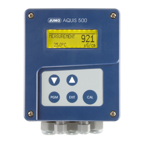
- Page 1 JUMO AQUIS 500 CR Transmitter/Controller for conductivity, TDS, resistivity and temperature Type 202565 B 202565.0 Operating Instructions V2.00/EN/00476321...
- Page 2 WARNING: A sudden malfunction of the devicedevice, or one of the sensors connected to it, could potentially result in dangerous, imprecise dosing! Suitable preventive measures must be in place to prevent this from happening. Note: Please read these Operating Instructions before placing the device in operation. Keep the manual in a place which is accessible to all users at all times.
-
Page 3: Table Of Contents
Contents Typographical conventions ............5 Warning signs ....................5 Note signs ....................5 Description ................6 Identifying the device version ..........7 Nameplate ....................7 Type designation ..................8 Scope of delivery ..................8 Accessories (in delivery package) ..............9 Accessories (optional) ................10 Mounting .................. 11 General .......................11 Surface mounting ..................11 Pipe installation set / weather protection roof ...........12... - Page 4 Contents Administrator level ..................36 6.10 Device info ....................43 6.11 Controller functions ..................44 Commissioning ............... 45 Fast start ....................45 Setup examples ..................46 Calibration ................66 General .......................66 Calibrating the relative cell constant ............66 Cell constants ....................68 Calibrating the temp. coefficient of the sample solution ......68 Calibration logbook ..................71 Setup program ................
-
Page 5: Typographical Conventions
1 Typographical conventions Warning signs Danger This symbol is used when there may be danger to personnel if the instructions are disregarded or not followed accurately! Caution This symbol is used when there may be damage to equipment or data if the instructions are ignored or not followed accurately! Caution This symbol is used where special care is required when handling components... -
Page 6: Description
2 Description General The device is used for the measurement/control of electrolytic conductivity, resistivity or the TDS value. In addition, the JUMO AQUIS 500 CR offers the option of displaying the measured conductivity according to a customer- specific table. Either 2-electrode or 4-electrode conductivity cells can be connected to the device. -
Page 7: Identifying The Device Version
3 Identifying the device version Nameplate on the TN: 00491200 JUMO AQUIS 500 CR transmitter Typ: 20256 / 0- 5 1 888 000 000 000- 3 2 /000 Fulda, Germany www.jumo.net F-Nr.: 0168122901016010001 AC 110..240V -15/+10% 48..63Hz ≤ 14VA The date of manufacture is coded in the 12th to 15th position (from the left) of the “F-Nr.”... -
Page 8: Type Designation
3 Identifying the device version Type designation (1) Basic type 202565 JUMO AQUIS 500 CR Transmitter/controller for conductivity, TDS, resistivity and temperature (2) Basic type extensions for panel mounting in surface-mountable housing (3) Output 1 (for principle measurement variable or continuous controller) no output analog output 0(4) —... -
Page 9: Accessories (In Delivery Package)
3 Identifying the device version Accessories (in delivery package) Contents Designation 3 x plug-in screw terminals 3 x small plug-in links 2 x cable clips for cable diameter > 5 mm 2 x cable clips for cable diameter < 5 mm 1 x cable clip for cable diameter <... -
Page 10: Accessories (Optional)
00456352 adapter (USB connecting cable) Fixing for suspension fitting 00453191 The pole-mounting kit is needed for mounting the protection cover. By using the pole-mounting kit, the JUMO AQUIS 500 can be fitted to a pole (e.g. support pillar or railing). -
Page 11: Mounting
4 Mounting General Mounting Find a location that ensures easy accessibility for the later calibration. location The fastening must be secure and must ensure low vibration for the device. Avoid direct sunlight! Permissible ambient temperature at the installation location: -10 to 55°C with max. -
Page 12: Pipe Installation Set / Weather Protection Roof
4 Mounting Pipe installation set / weather protection roof The pipe installation set for JUMO AQUIS 500 (part no.: 00483664) can be used to fasten the device (and optionally the protective roof for JUMO AQUIS 500, part no.: 00398161) onto pipes or railings with a diameter from 30 to 50 ø30-50... -
Page 13: Mounting In A Panel
4 Mounting Mounting in a panel Drilling template See section 12.2 "Panel cut-out", page The panel must be sufficiently thick to achieve the specified IP65 enclosure protection! Prepare the panel cut-out and holes based on the drill template. Place the control panel (1) with gasket (2) in the panel cut-out and fasten it with screws (2) spacing rollers (4) and nuts (5). - Page 14 4 Mounting Make the electrical connection. Break off the required flap(s) (3) from the cable cover (2) so that the cable can be laid in the cable path. Attach the cable cover (2) onto the control panel (1). Depth behind panel...
-
Page 15: Electrical Connection
5 Electrical connection Installation notes The electrical connection must only be carried out by qualified professional persons. The choice of cable, the installation and the electrical connection must conform to the requirements of VDE 0100 “Regulations on the Installation of Power Circuits with Nominal Voltages below 1000 V”... -
Page 16: Electrical Isolation
5 Electrical connection Electrical isolation Setup interface 3700 V AC Relay contacts Binary input 30 V AC 50 V DC Analog output 1 Main input 30 V AC 50 V DC Analog output 2 Secondary input (Pt100 / Pt1000) 3700 V AC Supply voltage Not with 12 —... -
Page 17: Preparatory Work
5 Electrical connection Preparatory work Opening the Prior to opening, loosen all cable fittings (2) so that the cables are device moveable. Push connection cable a little into the case so that enough cable reserve is available for opening. Loosen the 4 front-panel screws (1) of the case lid and pull them out as much as possible. -
Page 18: Connection Of Conductivity Cells
5 Electrical connection Connection of conductivity cells Items needed from the accessories Switchgear Switchgear Surface Surface mounting panel mounting panel mounting mounting 4 Fabricating the connecting The connecting cable between sensor and transmitter must be a cable shielded cable with a maximum diameter of 8 mm. Strip the cable as shown in the diagram. - Page 19 5 Electrical connection Insulate the screen at the cable end with heat shrink tube. Apply core ferrules to the ends of the conductors. Core ferrule dimensions see Chapter 5.1 “Installation notes”, page 15. Connecting The electrical connection for the surface-mountable housing is easily the cables accessible when the device is folded out.
- Page 20 5 Electrical connection 5.4.1 Conductivity cell with 2-electrode system figure without cable cover Lead the connecting cables in through the cable glands. Lay the signal cable as shown in the diagram. Use the cable clip (3) to clamp the signal cable to the shielding. Break off the required flap(s) from the cable cover so that the cable can be laid in the cable path.
- Page 21 5 Electrical connection 5.4.2 Conductivity cell with 4-electrode system figure without cable cover Lead the connecting cables in through the cable fittings. Lay the signal cable as shown in the diagram. Use the cable clip (3) to clamp the signal cable to the shielding. Break off the required flap(s) from the cable cover so that the cable can be laid in the cable path.
-
Page 22: Terminal Assignments
5 Electrical connection Terminal assignments Connection Screw terminals Supply voltage Supply voltage (23): 1 N (L-) 110 — 240 V AC -15/+10%, 48 — 63 Hz 2 L1 (L+) Supply voltage (25): 20 — 30 V AC/DC, 48 — 63 Hz Supply voltage (30): 12 —... - Page 23 5 Electrical connection Connection Screw terminals Binary input Outputs Analog output 1 + 13 - 14 0 — 20 mA resp. 20 — 0 mA, or 4 — 20 mA resp. 20 — 4 mA, 0 — 10 V resp. 10 — 0V (electrically isolated) Analog output 2 + 15...
-
Page 24: Operation
6 Operation Displays and controls (1) LC display (2) Control panel with 5 keys (3) Five cable glands (max.) -
Page 25: Lc Display
6 Operation LC display 6.2.1 Measurement mode (normal display) (10) (11) Relay K1 is active Output mode - Hand (manual operation) Relay K2 is active - Hold (hold operation) Binary input 1 is Conductivity/concentration actuated measurement Keypad is inhibited Unit for conductivity/ Device status (indications) concentration measurement - Alarm (e.g overrange) -
Page 26: Principle Of Operation
6 Operation Principle of operation Meas. mode > 3 sec EXIT CTRL. SETPOINTS SETPOINT 1 < 2 sec or timeout SETPOINT (adjustable) MIN/MAX VALUES < 2 sec EXIT OUTPUT LEVEL Controller 1 Controller < 2 s EXIT MANUAL MODE OVERVIEW <... - Page 27 6 Operation 6.3.1 Operation in levels Measurement mode (normal display); see Chapter 6.4 “Measurement mode”, page 29 CTRL. SETPOINTS MIN/MAX values see Chapter 6.5.1 “MIN/MAX values”, page 29 Output level display see Chapter 6.5.2 “Output level display”, page 30 Manual mode overview see Chapter 6.6.4 “MANUAL/ Simulation overview”, page OPERATOR LEVEL, see Chapter 6.8 “Operator level”, page 36...
- Page 28 6 Operation Measurement mode ADMINISTRATOR LEVEL BASIC SETTINGS, see Chapter 6.9.4 “Basic settings”, page 41 CELL TYPE CELL CONSTANT PROBE BREAK DETECT OPERATING MODE TEMP. COMP. TEMP. COEFF. RANGE 1 UNIT RANGE 1 DEC. POINT AUTORANGE RANGE 2 UNIT RANGE 2 DEC. POINT NEW DEVICE INITIALIZE CALIB.
-
Page 29: Measurement Mode
6 Operation Measurement mode 6.4.1 Normal display Presentation The normal display shows either the conductivity (compensated for the reference temperature) or the concentration and temperature of the medium being measured. MEASUREMENT -> Measurement mode 24.3°C -> Temperature of the sample medium 2032 µS/cm ->... - Page 30 6 Operation In order to return to the measurement mode: Press the key or wait for the timeout. EXIT If you change the basic setting or switch off the supply voltage, then the MIN and MAX values will be deleted. Measurements with overrange will be ignored.
-
Page 31: Manual Mode / Simulation Mode
In MANUAL mode the settings for "higher order controllers" are taken into consideration. 6.6.1 MANUAL mode via "higher order control functions" Higher order The JUMO AQUIS 500 is configured for higher order control functions when switching the following setting is made: functions User level / controller channel 1 or 2 / control type Limit value or pulse length or pulse frequency or modulating or continuous controller. - Page 32 To exit HOLD mode, press the keys for longer than 3 seconds. EXIT Control is no longer through the JUMO AQUIS 500. The output level of the controller channels is 0%. Controller channel 1 is activated by the key. In this case the output level of controller channel 1 is 100%.
- Page 33 Set Administrator level / Password / Parameter level / Switching output 1 or 2 / Manual mode no simulation, Inactive or Active. No simulation = No manual mode, control is via the JUMO AQUIS 500. Inactive = Relay K1 or K2 is de-energized.
- Page 34 Administrator level / Password / Parameter level / Analog output 1 or 2 / Simulation / Off or On. With "On" the output takes on the value of the "Simulation value" parameter. When the JUMO AQUIS is in display mode, the word MANUAL appears in the status line of the display. Deactivation Administrator level / Password / Parameter level / Analog output 1 or 2 / Simulation / Off.
-
Page 35: Hold Mode
6 Operation HOLD mode In HOLD status the outputs take on the states programmed in the relevant parameter (controller channel, switching output or analog output). This function can be used to "freeze" switching outputs and the analog outputs of the device. This means the current status of the output will be retained even when the measured value changes. -
Page 36: Operator Level
6 Operation Operator level All the parameters that have been enabled by the administrator (Administrator level, see “Administrator level”, page 36) can be edited in this level. All other parameters (marked by a key ) can only be read. Press the key for at least 3 seconds. - Page 37 6 Operation 6.9.1 Administrator levels ADMIN. LEVEL PASSWORD EXIT PARAMETER LEVEL timeout (adjustable) EXIT ENABLE LEVEL timeout EXIT BASIC SETTINGS timeout EXIT CALIBRATION LEVEL timeout EXIT CALIB. ENABLE timeout DELETE EXIT LOGBOOK timeout...
- Page 38 6 Operation 6.9.2 Parameter level Here you can make the same settings as at the operator level. Since the user has administrator rights in this case, parameters can also be altered that would be locked at the operator level. For the list of adjustable parameters, see Chapter 6.8 “Operator level”, page 36ff.
- Page 39 6 Operation Reset time Derivative time Pulse period Min. ON time Output level limit Max. pulse frequency Hysteresis Pull-in delay Drop-out delay Controller alarm In Hold mode In event of error MAX process value MIN process value CNTRL.SPEC.FUNCT. (Reglersonderfunktion) I switch-off separate controllers Manual mode SWITCH OUTPUT 1 or SWITCH OUTPUT 2...
- Page 40 6 Operation Output Analog process value output Continous control- ler Principal mea- Principal measure- Temperature surement variable ment variable DISPLAY Language Lighting LCD inverse Meas. display type Upper display Lower display Bar graph calibration start Bar graph calibration end MIN/MAX reset Operator timeout Contrast...
-
Page 41: Basic Settings
6 Operation 6.9.4 Basic settings The basic settings for the device are defined at this level. The parameters are altered by keys. Use the key to select the next parameter. Cell type 2-wire 4-wire Cell constant Cell constant 0.01 / 0.1 / 0.5 / 0.01 / 0.1 / 0.5 / 0.5 /1.0 1.0 / 3.0 / 10.0... -
Page 42: Calibration Level
6 Operation If you leave the "Basic settings" level with EXIT, all changes will be discarded and the previous settings will be restored. 6.9.5 Calibration level LINEAR TEMP.CO. (linear temperature coefficient) see Chapter 8.4 “Calibrating the temp. coefficient of the sample solution”, page 68. -
Page 43: Device Info
6 Operation 6.9.7 Delete logbook REALLY DELETE LOGBOOK ? YES / NO 6.10 Device info The present configuration for all important parameters is shown here. e.g. CELL TYPE -> 2-WIRE CELL CONSTANT -> 1.0 PROBE BREAK DETECT -> OFF OP. MODE ->... -
Page 44: Controller Functions
6 Operation 6.11 Controller functions Simple In the JUMO AQUIS 500, simple switching functions, such as alarm contacts switching and limit comparators or the signal from the calibration timer, are configured at functions the parameter level, through the parameters for “Switching output 1 or 2”. -
Page 45: Commissioning
7 Commissioning Fast start This is a recommendation for configuring the device reliably in a short time. If you check the setting options from this list before starting the configuration, you can avoid timeouts during configuration. Mount the device, see Chapter 4 “Mounting”, page 11. Install the device, see Chapter 5 “Electrical connection”, page 15 ff. -
Page 46: Setup Examples
7 Commissioning Setup examples 7.2.1 Measuring drinking water with a 2-electrode cell Measurement range: 0 — 1000 µS/cm Display: No decimal place Cell constant K: 1.0 1/cm Output signal: 4 — 20 mA Temperature compensation: Linear Temperature measurement: By Pt100 Controller function: Limit controller, MAX function Limit:... - Page 47 7 Commissioning Call up basic settings ADMIN. LEVEL PASSWORD EXIT PARAMETER LEVEL timeout (adjustable) EXIT ENABLE LEVEL timeout EXIT BASIC SETTINGS timeout continue on next page EXIT CALIBRATION LEVEL timeout EXIT CALIB. ENABLE timeout EXIT DELETE LOGBOOK timeout...
- Page 48 7 Commissioning Basic settings Cell type for main input: procedure 2-wire 4-wire Cell constant Cell constant 0.01 / 0.1 / 0.5 / 0.01 / 0.1 / 0.5 / 0.5 /1.0 1.0 / 3.0 / 10.0 / 3.0 / 10.0 Contamination detection Off / On Probe break detection Off / On...
- Page 49 7 Commissioning Call up the parameter level ADMIN. LEVEL PASSWORD EXIT PARAMETER LEVEL continue on timeout next page (adjustable) EXIT ENABLE LEVEL timeout EXIT BASIC SETTINGS timeout EXIT CALIBRATION LEVEL timeout EXIT CALIB. ENABLE timeout DELETE EXIT LOGBOOK timeout...
- Page 50 7 Commissioning Concluding device settings Input for Sensor type: Pt100/Pt1000 temperature Unit: °C Filter time constant: 00:00:02 Offset: 0.0°C Controller Controller type: Limit channel 1 Setpoint: 600 µS/cm MIN/MAX contact: As required Hysteresis: As required Pull-in delay: As required Drop-out delay: As required Controller alarm: As required...
- Page 51 7 Commissioning 7.2.2 Measuring highly-purified water with a 2-electrode cell Measurement range: 0 — 2 µS/cm Display: 2 decimal places Cell constant K: 0.01 1/cm Output signal: 0 — 20 mA Temperature compensation: Off Temperature measurement: By Pt100 Controller function: USP contact, as per USP <645>...
- Page 52 7 Commissioning Call up basic settings ADMIN. LEVEL PASSWORD EXIT PARAMETER LEVEL timeout (adjustable) EXIT ENABLE LEVEL timeout EXIT BASIC SETTINGS timeout continue on next page CALIBRATION EXIT LEVEL timeout CALIB. EXIT ENABLE timeout EXIT DELETE LOGBOOK timeout...
- Page 53 7 Commissioning Basic settings Cell type for the main input: 2-wire 4-wire procedure Cell constant Cell constant 0.01 / 0.1 / 0.5 / 0.01 / 0.1 / 0.5 / 1.0 / 3.0 / 10.0 0.5 /1.0 / 3.0 / 10.0 Contamination detection Off / On Probe break detection...
- Page 54 7 Commissioning Call up parameter level ADMIN. LEVEL PASSWORD EXIT PARAMETER LEVEL continue on timeout next page (adjustable) EXIT ENABLE LEVEL timeout EXIT BASIC SETTINGS timeout CALIBRATION EXIT LEVEL timeout CALIB. EXIT ENABLE timeout DELETE EXIT LOGBOOK timeout...
- Page 55 7 Commissioning Concluding device settings Input for Sensor type: Pt100/Pt1000 temperature Unit: °C Filter time constant: 00:00:02 Offset: 0.0°C Controller Controller type : channel 1 Controller Controller type : channel 2 Switching Function: output 1 Switching Function: No function output 2 Analog output 1 Signal selector: Main value...
- Page 56 7 Commissioning 7.2.3 Measuring highly-purified water with a 2-electrode cell Measurement range: 0 — 20 MΩ x cm Display: 2 decimal places Cell constant K: 0.01 1/cm Relative cell constant as per test report for the cell: 102.5% Output signal: 4 —...
- Page 57 7 Commissioning Call up basic settings ADMIN. LEVEL PASSWORD EXIT PARAMETER LEVEL timeout (adjustable) EXIT ENABLE LEVEL timeout EXIT BASIC SETTINGS timeout continue on next page EXIT CALIBRATION LEVEL timeout EXIT CALIB. ENABLE timeout DELETE EXIT LOGBOOK timeout...
- Page 58 7 Commissioning Basic settings Cell type for main input: procedure 2-wire 4-wire Cell constant Cell constant 0.01 / 0.1 / 0.5 / 0.01 / 0.1 / 0.5 / 0.5 /1.0 1.0 / 3.0 / 10.0 / 3.0 / 10.0 Contamination detection Off / On Probe break detection Off / On...
- Page 59 7 Commissioning Call up parameter level ADMIN. LEVEL PASSWORD EXIT PARAMETER LEVEL continue on timeout next page (adjustable) EXIT ENABLE LEVEL timeout EXIT BASIC SETTINGS timeout CALIBRATION EXIT LEVEL timeout EXIT CALIB. ENABLE timeout EXIT DELETE LOGBOOK timeout...
- Page 60 7 Commissioning Concluding device settings Input for Cell constant: 0.01 conductivity Relative cell constant: 102.5% Offset for the meas. range: 0.0°C Temperature compensation: ASTM D1125-95 Filter time constant: As required Calibration interval: As required Input for Sensor type: Pt100/Pt1000 temperature Unit: °C Filter time constant:...
- Page 61 7 Commissioning 7.2.4 Measuring with autorange and a 2-electrode cell Meas. range 1: 0 — 2 µS/cm Display for range 1: 2 decimal places Meas. range 2: 0 — 200 µS/cm Display for range 2: 1 decimal place Cell constant K: 0.1 1/cm Output signal: 4 —...
- Page 62 7 Commissioning Call up basic settings ADMIN. LEVEL PASSWORD EXIT PARAMETER LEVEL timeout (adjustable) EXIT ENABLE LEVEL timeout EXIT BASIC SETTINGS timeout continue on next page EXIT CALIBRATION LEVEL timeout EXIT CALIB. ENABLE timeout DELETE EXIT LOGBOOK timeout...
- Page 63 7 Commissioning Basic settings Cell type for main input: procedure 2-wire 4-wire Cell constant Cell constant 0.01 / 0.1 / 0.5 / 0.01 / 0.1 / 0.5 / 1.0 / 3.0 / 10.0 / 3.0 / 10.0 0.5 /1.0 Contamination detection Off / On Probe break detection Off / On...
- Page 64 7 Commissioning Call up parameter level ADMIN. LEVEL PASSWORD EXIT PARAMETER LEVEL continue on timeout next page (adjustable) EXIT ENABLE LEVEL timeout EXIT BASIC SETTINGS timeout CALIBRATION EXIT LEVEL timeout EXIT CALIB. ENABLE timeout DELETE EXIT LOGBOOK timeout...
- Page 65 7 Commissioning Concluding device settings Input for Sensor type: Pt100/Pt1000 temperature Unit: °C Filter time constant: 00:00:02 Offset: 0.0°C Controller Controller type : channel 1 Controller Controller type : channel 2 Switching Function: Autorange output 1 Switching Function: No function output 2 Analog output 1 Signal selector:...
-
Page 66: Calibration
EMC. More information on highly-purified water measurement in form of a scientific paper can be found on the Internet at www.jumo.de. For this purpose, enter the keyword "FAS 614" into the search box. - Page 67 8 Calibration - The transmitter must be in the measurement mode. Immerse the conductivity sensor in a reference solution with a known conductivity. The temperature of the sample solution must remain constant during calibration! If calibration has been enabled in the administrator level for the user, then the procedure can be started by pressing the key.
-
Page 68: Cell Constants
8 Calibration The present measured value and temperature will be displayed. Cell constants 2-electrode Cell constant Setting range for Resulting usable systems relative cell constant range [1/cm] [1/cm] 0.01 20 — 500% 0.002 — 0.05 0.02 — 0.5 0.2 — 5 0.6 —... - Page 69 8 Calibration Immerse the conductivity sensor in a sample of the solution to be measured. If calibration has been enabled in the administrator level for the user, then the procedure can be started by pressing the key. If calibration has not been enabled for the user, then this must be implemented in the administrator level / calibration level (the password 300 is required).
- Page 70 8 Calibration Press the key. The LC display now shows the conductivity on the right (399µS/cm) at the current temperature (24.3°C). On the left, you can see the other temperatures – T1 (25°C) and T2 (70.0°C) – that are to be used. Press the key.
-
Page 71: Calibration Logbook
8 Calibration The transmitter is now in the measurement mode, and shows the compensated conductivity of the solution. Calibration logbook The most recent calibration that was performed successfully is recorded in the calibration logbook. - Relative cell constant (CELL CONST.) = 102.9%. -
Page 72: Setup Program
9 Setup program Function Configurable The setup program (available as an option) can be used for easy adaptation of parameters the device to the requirements. - Setting the measurement range and the range limits. - Setting the response of the outputs to an out-of-range signal. - Setting the functions of the switching outputs K1 and K2. -
Page 73: Eliminating Faults And Malfunctions
10 Eliminating faults and malfunctions 10.1 Possible faults Problem Possible cause Measures No measurement display Supply voltage Supply voltage missing should be checked, current output also check terminals. Measurement display Sensor not immersed in Top up the reservoir. 000 or medium, Analog output 0/4 mA or reservoir level too low... -
Page 74: Checking The Device
10 Eliminating faults and malfunctions 10.2 Checking the device General The device is calibrated at the factory and is maintenance-free. If, nevertheless, measurement deviations appear with no apparent cause, the transmitter can be tested as follows. 10.2.1 Reference liquid test Test sequence Prepare the conductivity test solution in a container of adequate size. -
Page 75: Appendix
11 Appendix 11.1 Operator level parameters If a number of device parameters have to be modified in the device, then it is advisable to note them in the table below, and then modify these parameters in the sequence given. The following list shows the maximum number of parameters that can be altered. - Page 76 11 Appendix Parameter Selection / value range Factory setting setting Proportional band 0 — 9999 Reset time 0 — 9999 Derivative time 0 — 999 Pulse period 2.5 — 20 — 999.5 Minimum ON time 0.5 — 999.5 Output level limit 0 —...
- Page 77 11 Appendix Parameter Selection / value range Factory setting setting In Hold mode FROZEN 100% In event of error FROZEN 100% MAX setpoint 0 — 9999 MIN setpoint 0 — 9999 Controller special function I switch-off INACTIVE ACTIVE Separate controllers Manual mode LOCKED PULSED...
- Page 78 11 Appendix Parameter Selection / value range Factory setting setting Switching output 2 Function NO FUNCTION CONTROLLER 1 CONTROLLER 2 CTRLR ALARM 1 CTRLR ALARM 2 CTRLR ALARM AF1 MAIN VAR. AF2 MAIN VAR. AF7 MAIN VAR. AF8 MAIN VAR. AF1 TEMP.
- Page 79 11 Appendix Parameter Selection / value range Factory setting setting Safe value 0 — 22 mA Simulation Simulation value 0 — 22 mA Analog output 2 Signal selector TEMPERATURE CONTROLLER 1 CONTROLLER 2 Signal type 0 — 20 mA 20 — 0 mA 4 —...
- Page 80 11 Appendix Parameter Selection / value range Factory setting setting Lower display TEMPERATURE OUTP. LEVEL 1 OUTP. LEVEL 2 SETPOINT 1 SETPOINT 2 NONE COMPENSATED UNCOMPENSATED Upper display COMPENSATED UNCOMPENSATED TEMPERATURE OUTP. LEVEL 1 OUTP. LEVEL 2 SETPOINT 1 SETPOINT 2 NONE MIN/MAX reset Interface timeout...
-
Page 81: Parameter Explanations
11 Appendix 11.2 Parameter explanations TEMP. COMPENSATION LINEAR NATURAL WATER (permissible temperature range 0 to 36°C as per EN 27 888) ASTM D1125-95 (permissible temperature range 0 to 100°C) FUNCTION NO FUNCTION Alarm window AF1 MAIN VAR. Alarm window AF2 MAIN VAR. Limit function AF7 MAIN VAR. - Page 82 11 Appendix Trigger condition Trigger condition Pulse contact Pulse contact Pulse contact Pulse contact Triggering condition longer than Triggering condition shorter than pulse duration pulse duration Time Pulse duration Spacing Setpoint / Limit HySt Hysteresis Actual value / Measurement value MEAS.
- Page 83 11 Appendix TREND The operator can quickly recognize in which direction the measurement is changing. rising falling stable strong medium slightly slightly medium strong The measurement trend is derived from the last 10 measurements. With a 500 msec sampling cycle, this means that the last 5 seconds are taken into account.
- Page 84 11 Appendix Confirm selection with In order to return to the measurement mode: Press the key several times, or wait for the timeout. EXIT LOWER DISPLAY Operating mode Lower display Upper display This parameter is only available for the measurement display types NORMAL and TREND.
-
Page 85: Glossary
This factor varies from 0.55 to 1.0, and a typical value for drinking water is about 0.67. On modern devices, such as the JUMO AQUIS 500 CR, this factor can be individually entered, thus enabling the most accurate measurement. - Page 86 11 Appendix Detection of deposits Deposit detection can be activated for 4-electrode cells. During normal operation, it can happen that deposits form on electrodes. This has the result that a lower concentration is displayed than actually present. When the “deposit detection” function is activated, the device tells you when the cell needs to be serviced.
- Page 87 11 Appendix Pulse frequency controller (output is active for X > W and a P control structure) 100% Maximum pulse frequency 50% of pulse frequency No pulses Process value X Proportional band X X - W Setpoint W If the process value X exceeds setpoint W, the P controller will control proportionally to the control deviation.
- Page 88 11 Appendix Wash timer The wash timer can be used to implement automated sensor cleaning. This function is assigned to a switching output (1 or 2) for that purpose. The cycle duration (cleaning interval) can be adjusted in the range from 1 to 240 hours.
- Page 89 11 Appendix USP table, then the USP contact of the JUMO AQUIS 500 CR will switch. The limits are defined in steps. For example: at 8°C a value of 5°C is applied. Note: Temperature compensation must be switched off (temperature coefficient = 0) during monitoring.
- Page 90 11 Appendix Ph. Eur. pre-alarm The Ph. Eur. pre-alarm switches before the water quality reaches the set limit. The parameter: SWITCH OUTPUT 1 / FUNCTION / PRE-ALARM (0 — 100) is used to define a margin between the pre-alarm and the Ph.Eur. limit, as a percentage value referred to the active limit.
-
Page 91: Device Description
12 device description 12.1 Technical data 12.1.1 Inputs Main input Indication range Accuracy Temperature error ≤ 0.6% of range + 0.3 µS x cell µS/cm 0.000 — 9.999 0.2%/10°C 00.00 — 99.99 constant (K) 000.0 — 999.9 0000 — 9999 ≤... - Page 92 12 device description 12.1.5 4-electrode systems Cell constant Setting range of Resulting usable [1/cm] relative cell constant range [1/cm] 0.1 — 0.75 20 — 150% 0.2 — 1.5 12.1.6 Binary input Activation through floating contact Function key inhibit HOLD alarm suppression 12.1.7 Controller Controller type limit comparators, limit controller, pulse width controller, pulse frequency controller,...
-
Page 93: Standard Accessories
12 device description 12.1.13 Housing Material Cable entry cable glands, 3xM16 and 2xM12 max. Special feature venting device to prevent condensation -10 to 50°C Ambient temperature range (the specified accuracy is adhered to within this range) Operating temperature range -15 to 65°C (device is operational) Storage temperature range -30 to 70°C... - Page 94 12 device description...
-
Page 95: Panel Cut-Out
12 device description 12.2 Panel cut-out 100.5 Note: 1. Fix template to panel. 2. Drill holes ( 4.5 mm and 10 mm dia.) 3. Cut out the section within the marked lines. 4. Deburr. In order to ensure the enclosure protection as per data sheet, the panel must be of adequate thickness and stability. - Page 96 12 device description...
-
Page 97: Index
13 Index MIN/MAX values Mounting location – Accessories Administrator Analog output Nameplate Normal display Binary input Block diagram Operation in levels Operator Output Cable routing Output level display Calibration enable Outputs Conductivity input Overview of MANUAL mode Conductor Conductor cross-sections Connection of conductivity cell (2-electrode Panel mounting system) - Page 98 13 Index...
- Page 100 JUMO GmbH & Co. KG JUMO Instrument Co. Ltd. JUMO Process Control, Inc. Street address: JUMO House 6733 Myers Road Moritz-Juchheim-Straße 1 Temple Bank, Riverway East Syracuse, NY 13057, USA 36039 Fulda, Germany Harlow - Essex CM20 2DY, UK Phone:...
Need help?
Do you have a question about the AQUIS 500 CR and is the answer not in the manual?
Questions and answers