
Related Manuals for JUMO 404304 Series


Summary of Contents for JUMO 404304 Series
- Page 1 Pressure and differential pressure transmitters Operating Instructions 40430400T90Z000K000 EN/00392602...
-
Page 3: Table Of Contents
Content Typographical conventions ......................5 Warning signs ............................5 Note signs ............................5 General .............................. 6 Preface ..............................6 Application ............................7 Identifying the device vision ......................8 Order details ............................8 Mounting ............................10 Installation ............................11 Electrical connection .......................... 11 Commissioning .......................... -
Page 4: Typographical Conventions
1 Typographical conventions Warning signs Danger This sign is used when there may be danger to personnel if the instructions are disregarded or not followed accurately. Caution This sign is used when there may be damage to equipment or data if the instructions are disregarded or not followed accurately. - Page 5 2 General Preface Please read these Operating Instructions before commissioning the instrument. Keep the instructions in a place which is accessible to all users at all times. Please assist us to improve these operating instructions, where necessary. Your suggestions will be welcome. All the necessary settings are described in this manual.
-
Page 6: General
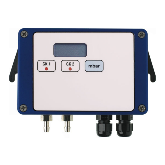
2 General Application General note Pressure and differential pressure transmitters Type 404304 are used for mea- suring very low pressures. Corresponding to the measuring range, the CuBe diaphragm inside the instrument is very sensitive. Do not blow into the pressure connections, as this may damage or destroy the instrument. - Page 7 3 Identifying the device vision Order details (1) Basic type 404304 Pressure transmitter with inductive measuring system (2) Basic type extensions none with one limit contact with two limit contacts LCD readout, 31/2-digit with one limit contact and LCD readout, 31/2-digit with two limit contacts and LCD readout, 31/2-digit (3) Nominal input range 0 to 10 Pa...
-
Page 8: Identifying The Device Vision
3 Identifying the device vision (4) Output 0 to 20 mA 0 to 20 mA, square root 4 to 20 mA, 2-wire 4 to 20 mA 4 to 20 mA, square root 0 to 10 V 0 to 10 V, square root 0 to 20 mA, extended response time 0 to 20 mA, square root, extended response time 0 to 20 mA, 2-wire, extended response time... -
Page 9: Mounting
4 Mounting Fixing Use the lugs to fix the instrument. The instrument should preferably be fixed vertically (pressure connections below), since it has been factory-calibrated in this posi- tion. This ensures that no condensate from the pressure lines will enter the measuring system. -
Page 10: Installation
5 Installation Electrical connection When connecting the instrument, please observe the VDE regulati- ons concerning work with mains supply voltage, as well as the regulations of the trade insurance associations regarding work on and with electrical equipment and installations. Never connect the supply voltage to the output terminals! For the required supply voltage, see nameplate. - Page 11 5 Installation Connection 2-wire Multimeter TP4 OFFSET TP3 - SPAN Time control TP2 + SPAN TP1 ZERO Supply TP5 LCD Connection Terminals Terminal block Output 4 to 20 mA, 2-wire DC 12 to 32 V proportional current in supply line...
-
Page 12: Commissioning
6 Commissioning After The output signal can be measured after the supply voltage has been con- connecting the nected. supply voltage For gauge pressure measurement, connect the pressure to be measured to the “+” input. The other pressure connection remains open. -
Page 13: Calibration
7 Calibration Only adjust the instrument potentiometers listed in the instructions below! The other potentiometers are factory-set and must not be adjusted! Required aids • pressure generator • reference pressure measuring device • supply for pressure /differential pressure transmitter • voltmeter/ammeter (multimeter) Setup Setup 2-wire... - Page 14 8 Setting the limit contacts Rating of limit contact: 6 A max. at 230 VAC Required aids • pressure generator • supply for pressure/differential pressure transmitter • reference pressure measuring device or voltmeter/ammeter (multimeter) Controls TP3 TP4 5 6 7 8 9 10 TP7 TP8 Description...
- Page 15 8 Setting the limit contacts Potentiometer for switch-off delay of GK2 Setting range: 0 to 10 sec Potentiometer for switch-off delay of GK2 Setting range: 0 to 10 sec Jumper for switching point of GK1 in the positive/negative pressure ranges (for ± ranges) Bridge 1-2 =>...
- Page 16 8 Setting the limit contacts Multimeter connection for testing limit contact 2 (GK2) 1-3 => switching point of limit contact Example 1: measuring range 0 to 3 hPa, switching point at 1.5 hPA (50%) => 0.5 V Example 2: measuring range -2 to +8 hPa, switching point at +3.5 hPA (55%) =>...
-
Page 17: Setting The Limit Contacts
8 Setting the limit contacts Setting the limit contact The range 0—100% always corresponds to 0 to 1 V, e.g.: by using a pressure range 0 to +3 hPa corresponds to 0 to 1 V multimeter pressure range -3 to +3 hPa corresponds to -0.5 to +0.5 V pressure range -2 to +8 hPa corresponds to -0.2 to +0.8 V Connect multimeter to connector ST4 (for GK1) or ST5 (for GK2), see table above. - Page 18 JUMO GmbH & Co. KG JUMO Instrument Co. Ltd. JUMO Process Control, Inc. Street address: JUMO House 6733 Myers Road Moritz-Juchheim-Straße 1 Temple Bank, Riverway East Syracuse, NY 13057, USA 36039 Fulda, Germany Harlow, Essex, CM20 2DY, UK Delivery address:...
Need help?
Do you have a question about the 404304 Series and is the answer not in the manual?
Questions and answers