Dexter Laundry T-900 Operator's Manual
Industrial washer model t-900/950 on-premise n-series control
Hide thumbs
Also See for T-900:
- Parts & service manual (154 pages) ,
- Operators manual installation & operation instructions (340 pages) ,
- Service manual (116 pages)
Table of Contents
Advertisement
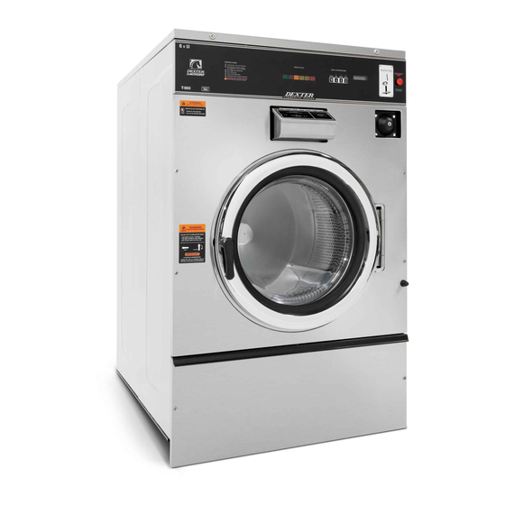
INDUSTRIAL WASHER
MODEL T-900/950 ON-PREMISE
N-SERIES CONTROL
WARNING: THIS WASHER IS EQUIPPED WITH DEVICES AND FEATURES RELATING TO ITS SAFE
OPERATION. TO AVOID INJURY OR ELECTRICAL SHOCK, DO NOT PERFORM ANY SERVICING UNLESS
QUALIFIED TO DO SO.
IT IS THE RESPONSIBILITY OF THE OWNER TO CHECK THIS EQUIPMENT ON A FREQUENT
BASIS TO ASSURE ITS SAFE OPERATION.
A machine should NOT be allowed to operate if any of the following occur:
-
Excessively high water level.
-
If machine is not connected to a properly grounded circuit.
-
If the door does not remain securely locked during the entire cycle.
-
Vibration or shaking from an inadequate mounting or foundation.
WARNING - SAFETY PRECAUTIONS
Always shut off power and water supply before servicing.
-
Do not overload the washer.
-
Do not open door when cylinder is in motion or it contains water.
-
Do not bypass any safety devices of this washer.
-
Do not use volatile or flammable substances in or near this washer.
-
Keep all panels in place. They protect against shock and injury and add rigidity to the washer.
-
PREVENTIVE MAINTENANCE REQUIREMENTS
DAILY
Check that the loading door remains securely locked and cannot be opened during an entire
-
cycle.
Check the water connections for leaks.
-
Clean the top, front, and sides of the cabinet to remove residue.
-
Clean the soap dispenser and lid and check that all dispenser mounting screws are in-place and
-
tight.
Check the drain valve for leaking and that it opens properly.
-
Check the loading door for leaks. Clean the door seal of all foreign matter.
-
Leave the loading door open to aerate the washer when not in use.
-
QUARTERLY
Make sure the washer is inoperative by switching off the main power supply.
-
Check the V-belts for wear and proper tension.
-
Clean lint and other foreign matter from around motor.
-
Check all water connections for leaks.
-
Wipe and clean the inside of the washer and check that all electrical components are free of
-
moisture and dust.
Remove and clean water inlet hose filters. Replace if necessary.
-
Check anchor bolts. Retighten if necessary
-
IMPORTANT: Replace any and all panels that were removed to perform daily and/or quarterly
maintenance.
8514-244-001 REV PR page 1
OPERATOR'S MANUAL
INSTALLATION & OPERATION
INSTRUCTIONS
Please read this information and retain for reference.
Advertisement
Table of Contents

Subscribe to Our Youtube Channel
Related Manuals for Dexter Laundry T-900


Summary of Contents for Dexter Laundry T-900
- Page 1 INDUSTRIAL WASHER MODEL T-900/950 ON-PREMISE N-SERIES CONTROL OPERATOR’S MANUAL INSTALLATION & OPERATION INSTRUCTIONS Please read this information and retain for reference. WARNING: THIS WASHER IS EQUIPPED WITH DEVICES AND FEATURES RELATING TO ITS SAFE OPERATION. TO AVOID INJURY OR ELECTRICAL SHOCK, DO NOT PERFORM ANY SERVICING UNLESS QUALIFIED TO DO SO.
-
Page 2: Table Of Contents
MACHINE CONTROL PROGRAMMABLE COMPUTER UP TO 30 CYCLES SOLENOID OPERATED VALVES, 30-120 PSI T-900: 2 VALVES, 9 GAL/MIN (34 L/MIN) EACH WATER INLET T-950: 2 DUAL VALVES 9 GAL/MIN (34 L/MIN) EACH. 2 SINGLE VALVES 12 GAL/MIN (45 L/MIN) EACH. -
Page 3: Installation Instructions
Refer to Figures Figure 1-1 and Figure 1-2 for machine bolt-down dimensions. Contact a Dexter laundry equipment distributor for recommended steel mounting bases. If an elevated concrete pedestal is desired, it should be embedded into the existing floor. - Page 4 Figure 1-1: Concrete Pedestal Mounting Figure 1-2: Floor Outline 8514-244-001 REV PR page 4...
- Page 5 Figure 1-3: Machine Mounting Detail 8514-244-001 REV PR page 5...
- Page 6 Figure 1-4: T-900/950 Industrial Washer Mounting Diagram **NOTE: Top water valves shown in Figure 1-4 are only on T-950 model. 8514-244-001 REV PR page 6...
-
Page 7: Plumbing
PLUMBING Two (for T-900 models) or four (for T-950 models) 48 inch (1.22 m) water supply hoses are provided with each machine. The threaded connections on the hoses are ¾-11 ½ NHT. Separate hot and cold water lines must be supplied to the machine, maintaining 30 psi to 120 psi (207 kPa to 827 kPa) water flow pressure. -
Page 8: Installing The Electrical Connection
1.6.1 INSTALLING THE ELECTRICAL CONNECTION 1.6.1.1 Disconnect all power to the washer. 1.6.1.2 Locate the power terminal block cover in the upper left corner of the machine when viewed from the back. Remove the screw and lift out the cover. Connections are as shown in Figure 1-5. -
Page 9: Maximum Spin Speed Adjustment
N Series Washer Max Spin Model (Left) (Right) 24V ACM AVI ACI 10V M01 MI1 MI2 MI3 MI4 MI5 MI6 Speed 60 G T-600, T-900, 80 G T-1200 100 G Default Setting (No Jumper Required) 100 G T-950, T-1450 140 G... -
Page 10: Injection Source Connections
INJECTION SOURCE CONNECTIONS The washer control may be programmed to send six 120V output signals for a chemical injection system of up to four chemical sources. There are convenient electrical connection points for the injection pumps in the rear of the machine, as shown in Figure 1-5. The four independent pumps can be controlled through the signals A, B, C and D. -
Page 11: Washer Operation
WASHER OPERATION CONTROL BUTTONS There are four (4) push buttons that control the washer operation. Each button is shown in Figure 2-1, followed by an explanation of each button. Figure 2-1: Washer Control Keypad Layout SCROLL DOWN ARROW: Press momentarily / press and hold. Scroll Down decreases the cycle number displayed by one each time the switch is pressed. -
Page 12: Starting The Washer
STARTING THE WASHER 2.2.1 Turn on power to the washer. 2.2.2 Ensure washer is in “RUN” mode. Locate the “ADVANCE/RUN/PROGRAM” key switch and key. The current mode is indicated by the alignment of the key slot. If washer is not in “RUN” mode, insert and turn the key to the “RUN” position. -
Page 13: Optional Soak
long as these two buttons are pressed. 2.2.7 Add bleach if desired. If you wish to manually add bleach during the cycle, add bleach in the “BLEACH” compartment 3 minutes after the start of the “WASH” cycle. NOTE: Any additional washing chemicals may be added at the appropriate time by pouring into the round opening on the top of the washer. - Page 14 “READY” “FAULT” “RUN” Washer Condition LED Status Status Status Idle Mode (No Cylinder Movement) Tumbling Stop from Tumble FLASHING Ramp to Intermediate or Final Extract Spin Spinning (Intermediate or Final) Stop from Spin FLASHING (Intermediate or Final) Faulted Table 4: Variable Frequency Drive Indicators 8514-244-001 REV PR page 14...
-
Page 15: Machine Programming Instructions
MACHINE PROGRAMMING INSTRUCTIONS This Dexter T-900/950 computer control OPL machine has 30 different selectable cycles; 29 of the 30 cycles are preset with the most common industry applications. See section 3.3 for complete cycle information. If these cycle settings do not meet the required application, each cycle is reprogrammable by the user simply and reliably. - Page 16 3.1.6 Press “ENTER” to display the settings. Available settings to alter in each bath are Cycle Time, Water Temperature, Water Level, Injection Source, and Spin Time. 3.1.7 Input settings. The first setting to alter is the Cycle Time as indicated by the “CYCLE TIME”...
-
Page 17: Programming A New Cycle
3.1.8 Program another bath. If desired, repeat steps 3.1.5 through 3.1.7 to program another bath. Otherwise, continue to the next step. 3.1.9 Program another cycle. To program a different cycle when any of the nine bath LEDs are illuminated, press the “EXIT” button. The “SELECT CYCLE” LED will immediately illuminate. -
Page 18: Default Washer Cycle Programs
DEFAULT WASHER CYCLE PROGRAMS The factory default cycles pre-programmed into the washer are listed with each bath and setting option in this section. All wash cycles can be reprogrammed, refer to section 3.1 for instructions. To reset all customized programs back to original factory default settings, refer to section 3.5 and complete step 14 of the Test Diagnostic Cycle. - Page 19 Cycle 1 Shirts - No Starch (Shirt/Laundry) Bath Cycle Water Water Spin Time Bath Injection Source Time (min.) Temp. Level (min.) Flush Prewash Wash 5 (Detergent/Bleach) Rinse 1 Rinse 2 Rinse 3 Rinse 4 Rinse 5 Final Rinse Cycle 2 Shirts - Starch (Shirt/Laundry) Bath Cycle Water...
- Page 20 Cycle 4 White Pillowcases (Hotel/Motel) Bath Cycle Water Water Spin Time Bath Injection Source Time (min.) Temp. Level (min.) Flush 1 (Detergent) Prewash Wash 2 (Bleach) Rinse 1 Rinse 2 Rinse 3 Rinse 4 Rinse 5 Final Rinse 4 (Sour/Softener) Cycle 5 White Towels (Hotel/Motel) Bath Cycle...
- Page 21 Cycle 7 Delicate (Hotel/Motel) Bath Cycle Water Water Spin Time Bath Injection Source Time (min.) Temp. Level (min.) Flush Prewash Wash 5 (Detergent/Bleach) Rinse 1 Rinse 2 Rinse 3 Rinse 4 Rinse 5 Final Rinse 4 (Sour/Softener) Cycle 8 Rags and Mops (Hotel/Motel) Bath Cycle Water Water...
- Page 22 Cycle 10 Stain Treatment – Chlorine Bleach (Hotel/Motel) Bath Cycle Water Water Spin Time Bath Injection Source Time (min.) Temp. Level (min.) Flush Prewash Wash 5 (Detergent/Bleach) Rinse 1 Rinse 2 Rinse 3 Rinse 4 Rinse 5 Final Rinse Cycle 11 Reclaim Part 1 (Hotel/Motel) Bath Cycle Water...
- Page 23 Cycle 13 Sheets and Pillowcases (Health Care) Bath Cycle Water Water Spin Time Bath Injection Source Time (min.) Temp. Level (min.) Flush Prewash Wash 1 (Detergent) Rinse 1 2 (Bleach) Rinse 2 Rinse 3 Rinse 4 Rinse 5 Final Rinse 4 (Sour/Softener) Cycle 14 Towels (Health Care)
- Page 24 Cycle 16 Personals (Health Care) Bath Cycle Water Water Spin Time Bath Injection Source Time (min.) Temp. Level (min.) Flush Prewash Wash 5 (Detergent/Bleach) Rinse 1 Rinse 2 Rinse 3 Rinse 4 Rinse 5 Final Rinse 4 (Sour/Softener) Cycle 17 Delicate (Health Care) Bath Cycle Water...
- Page 25 Cycle 19 Colored Cotton Table Linen (Food & Beverage) Bath Cycle Water Water Spin Time Bath Injection Source Time (min.) Temp. Level (min.) Flush Prewash Wash 1 (Detergent) Rinse 1 2 (Bleach) Rinse 2 Rinse 3 Rinse 4 Rinse 5 Final Rinse 6 (Sour/Starch) Cycle 20...
- Page 26 Cycle 22 White Chef Coats (Food & Beverage) Bath Cycle Water Water Spin Time Bath Injection Source Time (min.) Temp. Level (min.) Flush 1 (Detergent) Prewash Wash 1 (Detergent) Rinse 1 Rinse 2 2 (Bleach) Rinse 3 Rinse 4 Rinse 5 Final Rinse 4 (Sour) Cycle 23...
- Page 27 Cycle 25 White/Colored 100% Polyester Table Linen (Food & Beverage) Bath Cycle Water Water Spin Time Bath Injection Source Time (min.) Temp. Level (min.) Flush Prewash Wash 5 (Detergent/Bleach) Rinse 1 Rinse 2 Rinse 3 Rinse 4 Rinse 5 Final Rinse 6 (Sour/Starch) Cycle 26 White Chef Coats (Food &...
- Page 28 Cycle 28 Oxygen Bleach Terry (Other) Bath Cycle Water Water Spin Time Bath Injection Source Time (min.) Temp. Level (min.) Flush Prewash Wash 5 (Detergent/Bleach) Rinse 1 Rinse 2 Rinse 3 Rinse 4 Rinse 5 Final Rinse 4 (Sour/Softener) Cycle 29 Oxygen Bleach Terry - No Iron (Other) Bath Cycle Water...
- Page 29 Cycle _____ Description _________________________________ Bath Cycle Water Water Spin Time Bath Injection Source Time (min.) Temp. Level (min.) Flush Prewash Wash Rinse 1 Rinse 2 Rinse 3 Rinse 4 Rinse 5 Final Rinse Cycle _____ Description _________________________________ Bath Cycle Water Water Spin Time Bath...
-
Page 30: Rapid Advance Mode
RAPID ADVANCE MODE Rapid Advance mode is a key-controlled override to interrupt the current cycle, drain the water, and advance to the next mode of the wash cycle, including Pre Wash, Wash, Rinse 1, Rinse 2, Rinse 3, Rinse 4, Rinse 5, and Final Rinse. -
Page 31: Diagnostic Test Cycle
Notes: The cycle cannot be advanced during the “open drain” step of the baths. The cycle cannot be advanced when the hot and cold water valves to the tub are on after advancing during or after a chemical injection. The cycle cannot be advanced again while the hot and cold water valves to the tub are on after advancing when the water temperature was 65°C to 90°C. - Page 32 until the display reads “31”. 3.5.4 Press “START”. All lights will be on and “00” will be in the display. From this point, the operator must observe the functions of the washer with the washer top panel removed to ensure correct operation. Each step in this test will turn on an output on the I/O interface assembly, and the corresponding red LED on the I/O interface assembly will light.
- Page 33 Step 10: Tumble counter clockwise (REV. #14 LED will be lit) Step 11: Open Drain Valve (ensures that drain valve is open before spin) Step 12: Intermediate Extract (Rev. #13 and Speed 1 #15 red LEDs will be lit.) Step 13: High Speed Extract (Rev. #13, Speed 1 #15, and Speed 2 #16 red LEDs will be lit.) IMPORTANT: Do not use step 14 if you have customized any wash cycles as...
-
Page 34: Troubleshooting
TROUBLESHOOTING CAUTION: Label all wires prior to disconnection when servicing controls. Wiring errors can cause improper and dangerous operation. Verify proper operation after servicing. ATTENTION: Lors des opérations d'entretien des commandes, étiqueter tous les fils avant de les déconnecter. Toute erreur de câblage peut être une source de danger et de panne. If any of the following symptoms occur on this washer, check the suggested remedies listed below. - Page 35 Door will not Thermoactuator Check to see if thermoactuator(s) and/or its mechanism are stuck or open binding and not allowing the door lock motor to open. Check to be sure that red light on Input/Output PCB for locking thermoactuator is not illuminated and that Input/Output PCB is not sending 120VAC power to the locking thermoactuator during the last 70 seconds of the cycle.
- Page 36 Machine Variable Check small green, blue, orange, black, white, red wires (shielded cable) starts and Frequency Drive from the VFD to ensure a good connection at each termination point at advances and Motor drive or at relays and including all molex connectors. through 1.
- Page 37 Intermediate CPU board, Check input/output PCB for illuminated red speed 1 #15 and high speed 2 speed #1 Ribbon Cable #16 output lights. If no red output lights illuminated, check single red light works, but no Input/Output on CPU. Single red light should be illuminated. If light is flashing or not high speed on, remove power from washer for 2 minutes to reset board.
- Page 38 No hot water Water valves Check to ensure that water valve is operating. If not, check for 120VAC to in detergent water valve from Input/Output PCB. If 120VAC, change water valve. If no dispenser voltage check Input/Output PCB. Fill hose or Water Check water inlet screens for blockage and clean screens if necessary.
- Page 39 IMPORTANT TRANSIENT VOLTAGE SURGE SUPPRESSORS Like most electrical equipment your new machine can be damaged or have its life shortened by voltage surges due to lightning strikes which are not covered by factory warranty. Local power distribution problems also can be detrimental to the life of electrical components.
-
Page 40: Service And Parts
Strainer, Inlet Hose 4 or 8 Contact distributor or Dexter Laundry, Inc. if a steel-mounting base is required. For service and parts information, contact your local Dexter agent. To find your local Dexter agent, use the Distributor Locator at the website shown below. If a Dexter agent is not available, contact Dexter Laundry, Inc.
Need help?
Do you have a question about the T-900 and is the answer not in the manual?
Questions and answers