Table of Contents
Advertisement
Quick Links
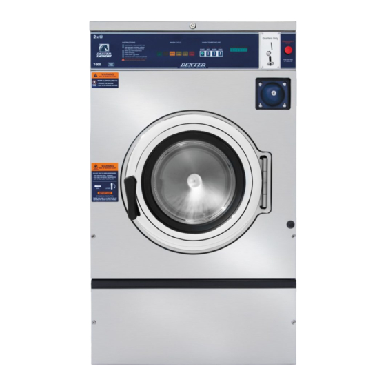
INDUSTRIAL WASHERS
MODEL T-350/450/650/750/950/1450 EXPRESS
MODEL T-675/975/1475 EXPRESS PLUS
ON-PREMISE O-SERIES CONTROL
WARNING - THIS WASHER IS EQUIPPED WITH DEVICES AND FEATURES RELATING TO ITS SAFE
OPERATION. TO AVOID INJURY OR ELECTRICAL SHOCK, DO NOT PERFORM ANY SERVICING UNLESS
QUALIFIED TO DO SO.
IT IS THE RESPONSIBILITY OF THE OWNER TO CHECK THIS EQUIPMENT ON A FREQUENT
BASIS TO ASSURE ITS SAFE OPERATION.
A machine should NOT be allowed to operate if any of the following occur:
-
Excessively high water level.
-
If machine is not connected to a properly grounded circuit.
-
If the door does not remain securely locked during the entire cycle.
-
Vibration or shaking from an inadequate mounting or foundation.
WARNING - SAFETY PRECAUTIONS
Always shut off power and water supply before servicing.
-
Do not overload the washer.
-
Do not open door when cylinder is in motion or it contains water.
-
Do not bypass any safety devices of this washer.
-
Do not use volatile or flammable substances in or near this washer.
-
Keep all panels in place. They protect against shock and injury and add rigidity to the washer.
-
PREVENTIVE MAINTENANCE REQUIREMENTS
DAILY
Check that the loading door remains securely locked and cannot be opened during an entire
-
cycle.
Clean the top, front, and sides of the cabinet to remove residue.
-
Clean the soap dispenser and lid and check that all dispenser mounting screws are in-place and
-
tight.
Check the loading door for leaks. Clean the door seal of all foreign matter.
-
Leave the loading door open to aerate the washer when not in use.
-
QUARTERLY
Make sure the washer is inoperative by switching off the main power supply.
-
Check the V-belts for wear and proper tension.
-
-
Clean lint and other foreign matter from around motor.
-
Check all water connections for leaks.
Check the drain valve for leaking and that it opens properly.
-
Wipe and clean the inside of the washer and check that all electrical components are free of
-
moisture and dust.
Remove and clean water inlet hose filters. Replace if necessary.
-
Check anchor bolts. Retighten if necessary.
-
IMPORTANT: Replace any and all panels that were removed to perform daily and/or quarterly
maintenance.
8514-290-001 REV E page 1
OPERATOR'S MANUAL
INSTALLATION & OPERATION
INSTRUCTIONS
Please read this information and retain for reference.
Advertisement
Table of Contents

Related Manuals for Dexter Laundry T-675 EXPRESS PLUS


Summary of Contents for Dexter Laundry T-675 EXPRESS PLUS
- Page 1 INDUSTRIAL WASHERS MODEL T-350/450/650/750/950/1450 EXPRESS MODEL T-675/975/1475 EXPRESS PLUS ON-PREMISE O-SERIES CONTROL OPERATOR’S MANUAL INSTALLATION & OPERATION INSTRUCTIONS Please read this information and retain for reference. WARNING - THIS WASHER IS EQUIPPED WITH DEVICES AND FEATURES RELATING TO ITS SAFE OPERATION.
-
Page 2: Table Of Contents
TABLE OF CONTENTS WASHER SPECIFICATION SHEETS ..............4 INSTALLATION INSTRUCTIONS ................6 FOUNDATION REQUIREMENTS ..............6 MOUNTING HEIGHT ..................6 FOUNDATION AND PAD OPTIONS ..............7 MACHINE ANCHORING ................. 9 MACHINE GROUTING .................. 10 FLOOR LOAD DATA..................11 MACHINE MOUNTING DETAILS ..............12 2.7.1 T-350 Machine Mounting Detail ............. - Page 3 OPERATING INSTRUCTIONS ................36 STARTING THE WASHER ................36 END OF CYCLE ................... 37 EMERGENCY STOP / SAFETY DOOR LOCK ............ 37 VARIABLE FREQUENCY DRIVE INDICATORS ..........38 MACHINE PROGRAMMING INSTRUCTIONS ............39 ENTER PROGRAMMING MODE ..............39 WATER LEVEL ADJUSTMENT ............... 40 WASHER ERROR MESSAGES ................
-
Page 4: Washer Specification Sheets
WASHER SPECIFICATION SHEETS EXPRESS MODELS T-350 T-450 T-650 T-750 T-950 T-1450 Capacity Dry Weight Capacity - lb (kg) (9.1) (13.6 kg) (18.1) (22.7) (27.2) (40.8) Cylinder Volume - cu ft (L) (76.5) (107.6 L) (170) (184.1) (254.9) 13.7 (388) Speed High Extract Speed - g (RPM) (819) (750 RPM) - Page 5 EXPRESS PLUS MODELS T-675 T-975 T-1475 Capacity Dry Weight Capacity - lb (kg) (18.1) (27.2) (40.8) Cylinder Volume - cu ft (L) (170) (254.9) 13.7 (388) Speed High Extract Speed - g (RPM) (993) (969) (816) Intermediate Extract Speed - g (RPM) (411) (375) (338)
-
Page 6: Installation Instructions
T-350: approximately 8 inches (203 mm) T-450: approximately 6 inches (152 mm) T-650/750/950/1450: approximately 4 inches (102 mm) T-675/975/1475: approximately 4 inches (102 mm) Contact a Dexter laundry equipment distributor for recommended steel mounting bases. Available steel mounting bases: Washer Part Number... -
Page 7: Foundation And Pad Options
T-950/975 9945-118-001 6” (152 mm) T-1450/1475 9945-145-001 4” (103 mm) If an elevated concrete pedestal is desired, it should be embedded and tied into the existing floor. DO NOT install a pad on top of the existing floor. Cut through existing floor as shown below. See Machine Mounting Detail Figures for floor thickness and bolt sizes. - Page 8 2.3.3 NEW PAD TIED TO EXISTING FLOOR: If the existing floor is not reinforced concrete that meets the minimum thickness requirements, DO NOT install a pad on top of the existing floor. The existing floor and the machine pad must be tied together as one piece as follows: Cut an opening through the existing floor that is wider and deeper than the washer as shown below.
-
Page 9: Machine Anchoring
2.3.3.2 NEW RAISED CONCRETE PEDESTAL TIED TO EXISTING FLOOR: 2.3.4 STEEL MOUNTING BASE ON CONCRETE FLOOR: MACHINE ANCHORING All installations require concrete floors and quality grade anchor bolts or expansion anchors. Mounting hardware is not provided with the machines. Refer to appropriate model Machine Mounting Detail Figures 1- 1, 1-2 and 1-3 for floor thickness and bolt sizes. -
Page 10: Machine Grouting
EXPANSION ANCHORS ARE NOT RECOMMENDED FOR USE IN RAISED CONCRETE PEDESTALS BECAUSE THE ANCHORS ARE TOO CLOSE TO AN EDGE, CAUSING IT TO BREAK OUT. ANCHORING OPTIONS: 2.4.1 Cast in place bolts headed by square fish plates. See Machine Mounting Detail Figures 1-1 thru 1-3 for exact washer model. Or after concrete has completely cured: 2.4.2 Use Hilti Adhesive System ‘HAS’... -
Page 11: Floor Load Data
2.5.4 Mix non-shrinking machinery grout according to the grout instructions. The grout should not be too runny or too firm. Completely fill the 1/2” [12.7] space between the washer base and the mounting surface. Force grout under all base angles and plates until completely filled. -
Page 12: Machine Mounting Details
MACHINE MOUNTING DETAILS FLOOR OUTLINE Figure 1-2 RAISED CONCRETE PEDESTAL MOUNTING OPTION MACHINE MOUNTING DETAIL Figure 1-1 Figure 1-3 2.7.1 T-350 Machine Mounting Detail 8514-290-001 REV E page 12... -
Page 13: T-350 Machine Side By Side Mounting Detail
SIDE BY SIDE MOUNTING DIMENSIONS Figure 1-4 2.7.2 T-350 Machine Side By Side Mounting Detail 8514-290-001 REV E page 13... -
Page 14: T-350 Industrial Washer Dimensions
2.7.3 T-350 Industrial Washer Dimensions 8514-290-001 REV E page 14... -
Page 15: T-450 Machine Mounting Detail
FLOOR OUTLINE Figure 1-2 RAISED CONCRETE PEDESTAL MOUNTING OPTION MACHINE MOUNTING DETAIL Figure 1-1 Figure 1-3 2.7.4 T-450 Machine Mounting Detail 8514-290-001 REV E page 15... -
Page 16: T-450 Machine Side By Side Mounting Detail
SIDE BY SIDE MOUNTING DIMENSIONS Figure 1-4 2.7.5 T-450 Machine Side by Side Mounting Detail 8514-290-001 REV E page 16... -
Page 17: T-450 Industrial Washer Dimensions
2.7.6 T-450 Industrial Washer Dimensions 8514-290-001 REV E page 17... -
Page 18: T-650/675 Machine Mounting Detail
FLOOR OUTLINE Figure 1-2 MACHINE MOUNTING DETAIL Figure 1-3 RAISED CONCRETE PEDESTAL MOUNTING OPTION Figure 1-1 2.7.7 T-650/675 Machine Mounting Detail 8514-290-001 REV E page 18... -
Page 19: T-650/675 Machine Side By Side Mounting Detail
SIDE BY SIDE MOUNTING DIMENSIONS Figure 1-4 2.7.8 T-650/675 Machine Side By Side Mounting Detail 8514-290-001 REV E page 19... -
Page 20: T-650/675 Industrial Washer Dimensions
2.7.9 T-650/675 Industrial Washer Dimensions 8514-290-001 REV E page 20... -
Page 21: T-750 Machine Mounting Detail
FLOOR OUTLINE Figure 1-2 MACHINE MOUNTING DETAIL Figure 1-3 RAISED CONCRETE PEDESTAL MOUNTING OPTION Figure 1-1 2.7.10 T-750 Machine Mounting Detail 8514-290-001 REV E page 21... -
Page 22: T-750 Machine Side By Side Mounting Detail
SIDE BY SIDE MOUNTING DIMENSIONS Figure 1-4 2.7.11 T-750 Machine Side By Side Mounting Detail 8514-290-001 REV E page 22... -
Page 23: T-750 Industrial Washer Dimensions
2.7.12 T-750 Industrial Washer Dimensions 8514-290-001 REV E page 23... -
Page 24: T-950/975 Machine Mounting Detail
FLOOR OUTLINE Figure 1-2 RAISED CONCRETE PEDESTAL MOUNTING OPTION MACHINE MOUNTING DETAIL Figure 1-3 Figure 1-1 2.7.13 T-950/975 Machine Mounting Detail 8514-290-001 REV E page 24... -
Page 25: T-950/975 Machine Side By Side Mounting Detail
SIDE BY SIDE MOUNTING DIMENSIONS Figure 1-4 2.7.14 T-950/975 Machine Side By Side Mounting Detail 8514-290-001 REV E page 25... -
Page 26: T-950/975 Industrial Washer Dimensions
2.7.15 T-950/975 Industrial Washer Dimensions 8514-290-001 REV E page 26... -
Page 27: T-1450/1475 Machine Mounting Detail
FLOOR OUTLINE Figure 1-2 MACHINE MOUNTING DETAIL RAISED CONCRETE PEDESTAL MOUNTING OPTION Figure 1-3 Figure 1-1 2.7.16 T-1450/1475 Machine Mounting Detail 8514-290-001 REV E page 27... -
Page 28: T-1450/1475 Machine Side By Side Mounting Detail
SIDE BY SIDE MOUNTING DIMENSIONS Figure 1-4 2.7.17 T-1450/1475 Machine Side By Side Mounting Detail 8514-290-001 REV E page 28... -
Page 29: T-1450/1475 Industrial Washer Dimensions
2.7.18 T-1450/1475 Industrial Washer Dimensions 8514-290-001 REV E page 29... -
Page 30: Plumbing
PLUMBING Water supply hoses are provided with each machine. The threaded connections on the hoses are ¾-11 ½ NHT for 60 Hz models and ¾-14 BSP for 50 Hz models. Separate hot and cold water lines must be supplied to the machine, maintaining 30 psi to 120 psi (207 kPa to 827 kPa) water flow pressure. - Page 31 WARNING: SHUT OFF POWER AND WATER BEFORE OPENING ANY SERVICE PANELS. ELECTRICAL CONNECTIONS 8514-290-001 REV E page 31...
-
Page 32: Installing The Electrical Connection
Ground. If there is a high leg, it must NOT be connected to L1 or L2. However, failure due to a voltage surge on the high leg is not covered by equipment warranty. Contact Dexter Laundry with any questions. 2.11.1.4... -
Page 33: Controls Transformer (208-240V 60 Hz Models Only)
2.11.3 CONTROLS TRANSFORMER (208-240V 60 Hz models only) The controls transformer is located inside the control trough and steps a range of 208 to 240 volts down to 115 volts and 24 volts. There are two terminals on the controls transformer for the primary (incoming) power. -
Page 34: Injection Source Connections
2.12 INJECTION SOURCE CONNECTIONS The washer control may be programmed to send ten 120VAC output signals for 60Hz models (or 24VAC for 50Hz) for a chemical injection system. The signals are not intended as a power source and must be limited to less than 100 milliamps of current. -
Page 35: Operation Check
2.13 OPERATION CHECK After all mounting, plumbing and electrical work is completed, select any desired wash cycle and run the machine through a complete wash cycle. Check for water leaks and verify proper operation. During intermediate spin and final spin, the cylinder should turn in a counterclockwise direction when viewed from the front of the machine. -
Page 36: Operating Instructions
OPERATING INSTRUCTIONS STARTING THE WASHER 3.1.1 Turn on power to the washer. 3.1.2 Load the laundry. Place laundry into the cylinder and latch the door securely. Be sure laundry does not get caught between the door gasket and tub front when closing the door. -
Page 37: End Of Cycle
END OF CYCLE A tone will sound (if programmed) and the display will indicate that the cycle has ended. The door can now be opened. Immediately remove contents of washer. Leave the door open when the machine is not in use. EMERGENCY STOP / SAFETY DOOR LOCK This machine is equipped with a safety door lock that locks the door when the cycle is started until the cycle is complete. -
Page 38: Variable Frequency Drive Indicators
VARIABLE FREQUENCY DRIVE INDICATORS There are three small colored LEDs located on the upper region of the Variable Frequency Drive (VFD). They are labeled as “READY”, “RUN”, and “FAULT” and can be used for troubleshooting. The definitions of the LEDs are listed in the table below. LED Status Washer Condition Steady Yellow... -
Page 39: Machine Programming Instructions
MACHINE PROGRAMMING INSTRUCTIONS ENTER PROGRAMMING MODE 4.1.1 In the cycle selection screen, scroll to Management View at the beginning of the cycle list and select enter. 4.1.2 Enter Passcode and confirm by pressing enter. 4.1.3 Select desired option. 4.1.3.1 Example EDIT CYCLES Cycles may be edited in the Edit Cycles selection. -
Page 40: Water Level Adjustment
WATER LEVEL ADJUSTMENT The water level of all baths can be adjusted by changing the switch settings on the electronic pressure sensor. On-premise washers are shipped with the pressure sensor harness connected to Switch #1 for “LO” level and Switch #2 for “HI” level. Water level adjustments can also be made in 1/4”... -
Page 41: Washer Error Messages
WASHER ERROR MESSAGES The O-Series washer control reacts to various abnormal conditions by displaying an Error message. These messages usually contain the “Error” text, and then a general description of the message. Below is a listing of Error messages separated by each potential displayed message in bold face. - Page 42 TEMP SENSOR SHORT Condition This error occurs when the control detects a short circuit from the temperature sensor. Action When detected, the control turns off the motor and all relays. There is no delay in the action once the criteria are met. Exit The machine will not start and the Error Code will continue to be displayed until the condition is no longer present.
- Page 43 There is no delay in the action once the criteria are met. Exit The Error Code will continue to be displayed until the in-progress cycle is stopped and the control is returned to Idle Mode. It will then reset automatically. Note This error code is disabled if the washer model does not have an Auxiliary Heating option...
- Page 44 return the Machine to Idle Mode. If the prompt to Reset is not available, power must be cycled to the machine to reset the error. MODEL JUMPER MISSING Condition This error occurs when there is no connection to Ground (Pin 7) on the Model Jumper Header.
- Page 45 Exit The machine will not start and the Error Code will continue to be displayed until the condition no longer exists and the prompt is followed to Reset the Error Code and return the Machine to Idle Mode. NON-DEXTER DRIVE Condition This error occurs when a non-Dexter VFD is installed in the machine.
- Page 46 Condition This error occurs when the control receives a message that the drive has experienced an overload condition. Action When detected, the control turns off the motor and all relays. There is no delay in the action once the criteria are met. Exit The machine will not start and the Error Code will continue to be displayed until the condition no longer exists and the prompt is...
- Page 47 DRIVE COMMUNICATION Condition This error occurs the control cannot communicate with the VFD. Action When detected, the control turns off the motor and all relays. There is no delay in the action once the criteria are met. Exit The machine will not start and the Error Code will continue to be displayed until the condition no longer exists and the prompt is followed to Reset the Error Code and return the Machine to Idle Mode.
- Page 48 Condition This error occurs when the programmed water level is not reached within 7 minutes. Action When detected at 7 minutes into the stage, the control will display the “SLOW FILL ERROR” prompt, alternating with the normal Cycle Progress screen at a rate of 5 seconds on, 5 seconds off. Otherwise the cycle will continue normally.
-
Page 49: Troubleshooting
TROUBLESHOOTING CAUTION: Label all wires prior to disconnection when servicing controls. Wiring errors can cause improper and dangerous operation. Verify proper operation after servicing. ATTENTION: Lors des opérations d'entretien des commandes, étiqueter tous les fils avant de les déconnecter. Toute erreur de câblage peut être une source de danger et de panne. If any of the following symptoms occur on this washer, check the suggested remedies listed below. - Page 50 adjust or replace door switch. Door will not Thermoactuator Check to see if thermoactuator(s) and/or its open mechanism is stuck or binding and not allowing the door lock mechanism to open. Check to be sure that the locking thermoactuator is not receiving 24VAC during the last 1 1/2 minutes of the cycle.
- Page 51 No cold water Water Valve Check coil continuity at terminals and to tub in Coil replace if no continuity. wash Water Inlet Check water inlet screens for blockage and Screens clean if necessary. Water Check to ensure that water is turned on and operating.
- Page 52 Machine does Review indicator lights displayed on VFD. not turn See VFD indicator section for more info. If no display, turn power off to machine at breaker for 2 minutes and turn power back on to reset. If still no display, replace VFD. Machine Review indicator lights displayed on VFD.
-
Page 53: Transient Voltage Surge Suppressors
TRANSIENT VOLTAGE SURGE SUPPRESSORS IMPORTANT Like most electrical equipment your new machine can be damaged or have its life shortened by voltage surges due to lightning strikes which are not covered by factory warranty. Local power distribution problems also can be detrimental to the life of electrical components. -
Page 54: Service And Parts
9565-003-001 (All) Strainer, Inlet Hose Contact distributor or Dexter Laundry, Inc. if a steel-mounting base is required. For service and parts information, contact your local Dexter agent. To find your local Dexter agent, use the Distributor Locator at the website shown below. If a Dexter agent is not available, contact Dexter Laundry, Inc.
Need help?
Do you have a question about the T-675 EXPRESS PLUS and is the answer not in the manual?
Questions and answers