Control 4 HC-250 Installation Manual
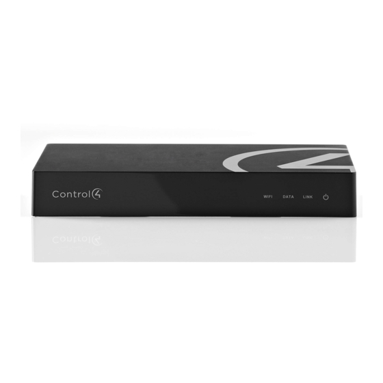
Controller, black
Hide thumbs
Also See for HC-250:
- Installation manual (7 pages) ,
- Quick start manual (2 pages) ,
- User manual
Table of Contents
Advertisement
HC-250 Controller
Installation Guide
Supported Model
• C4-HC250-BL – HC-250 Controller, Black
Introduction
The Control4® HC-250 Controller (HC-250) provides
ways to control lights, home theaters, distributed
audio and video systems, and other devices
controlled by Infrared (IR), IP, Serial, Contact, or Relay
connections. The Controller has a fast processor,
built-in WiFi, HDMI for audio and video, improved
ZigBee radio, and is perfect for smaller systems!
The HC-250 also provides extensive media
management for audio and video content: CDs,
DVDs, and Blu-ray Discs, or digital media stored on
connected devices. Use an external storage device
with USB or NAS connectivity to store music and
photos. The HC-250 fits easily behind a TV, stacked
with AV devices, or mounted on a rack using the
Rack Mount Kit (sold separately).
After you install and configure the HC-250 (using the
Composer Pro software) along with other system
components, your customers can control their
system using the On-Screen Navigator, MyHome
apps, System Remote Controls, Touch Screens, or
any other Control4-supported interface devices (sold
separately).
™
Box Contents
The following items are included in the HC-250 box:
• HC-250 Controller
• AC power cord
• IR emitters (4)
• Universal Television Mounting Plate
• Screws (4)
• Contact/Relay Terminal Block
• Ferrite clamps (4)
• Warranty Card
Accessories Available for Purchase
• Rack Mount Kit (C4-1URMK1B-B or C4-
1URMK2B-B)
• Serial Cable Kit (C4-CBL3.5-DB9B)
Warnings
WARNING!
To reduce the risk of electrical
shock, do not expose this apparatus to rain or
moisture.
AVERTISSEMENT!
choc électrique, n'exposez pas cet appareil à la
pluie ou à l'humidité.
CAUTION:
In an over-current condition on
USB or contact output the software disables
the output and then blinks the power LED for
10 seconds. When a USB overcurrent fault is
detected, you will see the power light blink the
LED five (5) times per second. When a contact
overcurrent fault is detected, you will see the
power light blink the LED 12 times a second.
After the 10-second blinking period is over the
over-current circuit will be re-enabled. If the
over-current condition remains, then the same
sequence will repeat itself.
ATTENTION :
Dans une condition de
surintensité sur USB ou sortie de contact le
logiciel désactive sortie, puis le DEL Power
clignote pendant 10 secondes. Quand une
erreur de condition de surintensité sur USB
est détectée, vous verrez le DEL Power
clignoté le DEL (5) fois par seconde et puis
quand un défaut de condition de surintensité
sur contact est détecté, vous verrez le DEL
Pour réduire le risque de
1
Advertisement
Table of Contents

Subscribe to Our Youtube Channel
Related Manuals for Control 4 HC-250


Summary of Contents for Control 4 HC-250
- Page 1 Box Contents ™ The following items are included in the HC-250 box: • HC-250 Controller • AC power cord HC-250 Controller • IR emitters (4) • Universal Television Mounting Plate Installation Guide • Screws (4) • Contact/Relay Terminal Block • Ferrite clamps (4) • Warranty Card...
-
Page 2: Specifications
125mA installation. Relay (1) AC - 36V, 2A (3) The HC-250 is only compatible with PoE DC - 24V, 2A injectors that have DC ground isolated from maximum operation (low voltage) AC ground. The easiest way to determine if Dimensions (H x W x D) 1.23”... -
Page 3: Front/Back View
The set contains a connection for Normally Opened (NO), Normally Closed (NC), and Common (COM). Installation Instructions To install the Controller: Ensure that the home network is in place before starting system setup. The HC-250 requires a... -
Page 4: Wall Mount Options
See “Wall Mount placed directly into a wall stud or studs. Using Options” below if mounting the HC-250 on a wall. the mounting plate as a template, screw the four Connect the HC-250 to the network. -
Page 5: Troubleshooting
Connect the IR Ports/Serial Ports IR Blaster (Optional) The HC-250 is also equipped with an IR blaster, for learning codes, which is located just left of the front The HC-250 provides four (4) IR ports; Ports 1 and LEDs. To use the blaster rather than an IR emitter:... -
Page 6: Factory/Network Resets
• Press the Factory Restore button, but do not hold it down. The Controller will reset. Identification Button (Network Reset) To reset the HC-250 network settings to the default, perform the following steps: Disconnect power to the HC-250. While pressing and holding the ID button on the back of the HC-250, power on the HC-250.
Need help?
Do you have a question about the HC-250 and is the answer not in the manual?
Questions and answers