Advertisement
Quick Links
Home Controller
HC-200
Installation Guide
Supported Model
C4-HC200B-E-B-NR-1 Home Controller HC-200
Introduction
The Control4® Home Controller HC-200 provides options for controlling lights, home
theaters, distributed audio systems, distributed video systems, and other devices controlled
using various protocols, such as Infra Red (IR) and Serial (see IR Out description). This ver-
sion comes with an improved processor, new Factory Restore button, and Flash support for
the On-Screen Navigators.
It provides extensive media management services for audio and video sources, such as
CDs and DVDs stored in connected devices. It also allows you to use an external storage
device with USB support for media storage. It also includes multi-zone audio capabilities,
sending music to rooms throughout the home.
When the Controller and other system components are installed and configured, users can
control the system using a number of interfaces, such as: On-Screen Navigator (included) or
a System Remote Control (sold separately).
What's in the Box
The following items are included in your Home Controller box:
•
Home Controller HC-200
•
AC to DC power adapter with power cord
•
IR emitters (4)
•
Universal Mounting Plate
•
Screws (4)
•
Home Controller HC-200 Installation Guide (this document). Note: You can find this
and other related documents online in the Products pages.
Accessories Available for Purchase
•
USB WiFi Adapter (C4-NWA-11G-USB)
•
Rack-Mount Kit (C4-1URMK1-B)
•
Serial Cable Kit (C4-CBL3.5MM-DB9)
Important Safety Instructions
1.
Read and keep these instructions.
2.
Heed all warnings and follow all instructions for this product in this and other Con-
trol4® documents included with or related to this product.
3.
Improper use of this product may result in potential electric shock.
4.
Do not use this product near water.
5.
Never spill liquid of any kind on this product.
6.
Clean this product only with a damp or dry cloth. Do not use liquid cleaners or aerosol
cleaners to clean the product.
7.
Install this product according to the manufacturer's instructions.
8.
Install this product according to the National Electrical Code ANSI/NFPA 70 and the
prevailing local codes and requirements.
9.
This product should be operated with the type of power indicated on the marked label.
If you are not sure of the type of power available, consult your Control4 dealer or local
power company.
10.
Slots and openings on a cabinet rack, and components used with this product are pro-
vided for ventilation, reliable operation, and protection from overheating of the product.
These slots and openings must not be blocked or covered.
11.
This product should never be placed near or over a radiator or heat register, or in a
built-in installation unless proper ventilation is provided.
12.
Never push objects of any kind into this product through cabinet slots because they
may touch dangerous voltage points or short out parts that could result in a fire or
electric shock.
13.
Only use the attachments and accessories included with this product or recommended
by Control4.
14.
Do not allow anything to rest on the power cord. Do not install or place this product
where people will walk on the cord.
15.
Do not use extension cords with any products in a Control4 system.
16.
If applicable, unplug this product during lightning storms or when unused for long
periods of time.
17.
Do not exceed the maximum wire size (if specified) in this guide.
18.
This product must be installed by qualified professionals only.
19.
Do not attempt to service this product yourself except as noted in this guide. Opening
or removing covers of internal components may expose you to dangerous voltage
points or other risks.
20.
Refer all servicing to qualified service personnel. Servicing is required when the ap-
paratus has been damaged or frayed in any way; for example, a power-supply cord or
plug is damaged, liquid has been spilled or objects have fallen into this product, this
product has been exposed to rain or moisture, this product does not operate normally,
or this product has been dropped.
WARNING! To reduce the risk of electrical shock, do not expose this apparatus
to rain or moisture.
AVERTISSEMENT! Pour réduire le risque de choc électrique, n'exposez pas cet
appareil à la pluie ou à l'humidité.
WARNUNG! Um das Risiko des elektrischen Schlages zu verringern, setzen Sie
diesen Apparat nicht Regen oder Feuchtigkeit aus.
Control4 Supported Devices
Control4 devices that communicate with this Controller include:
•
Touch Screens—All types and sizes (such as portable, tabletop, and in-wall, or 10", 7",
5", and mini)
•
LCD Keypads
•
Wireless 2, 3, & 6 Button Keypads
•
Wireless Thermostats
•
Speaker Points®
•
Audio Matrix Switch
•
Multi Channel Amplifiers
•
4-Zone Amplifiers
•
Multi Tuners (V1 or V2)
•
Wireless Dimmers
•
Wireless Switches
•
Wireless Outlet Dimmers
•
Wireless Outlet Switches
For a more information, refer to the Products pages at www.control4.com.
Requirements and Specifications
•
If you are using the Ethernet networking option, the Ethernet network should be in
place prior to starting the installation.
•
If you are using the WiFi networking option, you must install and set up the WiFi
adapter (sold separately) in order to complete the installation.
•
Software required for configuration is Composer Pro.
The Home Controller HC-200 specifications are:
Model Number
C4-HC200B-E-B-NR-1
Network Support
Ethernet—required (included)
WiFi--optional, requires a WiFi adapter (sold sepa-
rately)
Media Recognition
Online CD/DVD recognition and media information
service
Audio Playback Formats
MP3: 32kbps to 320kbps, CBR and VBR
Display
LED indicators
Power Requirements
100-240 VAC, 60/50 Hz, 0.50 A MAX
Dimensions
H x W x D: 1.44" (36.5 mm) x 8.55 (217 mm) x 5"
(127 mm) (with connectors and mounting plate)
Weight
1.8 lbs/0.82 kg
Additional Resources
The following resources are available to provide you with additional support.
•
Your Control4 Reseller
•
Control4 Web Site: http://www.control4.com
•
Composer online help
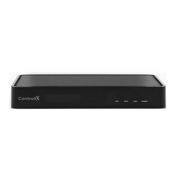
Front View
2
3
4
5
1
6
1.
IR Window / IR Blaster—For capturing third-party IR codes from hand-held devices
(such as remote controls) or blasting IR codes. The WiFi LED blinks red when captur-
ing IR codes.
2.
WiFi LED—This LED blinks orange and then blue during the boot process. When the
operating system is running, the WiFi driver changes the LED color depending on
the signal strength of its connection to its associated access point. Colors and signal
strength are as follows: orange=Fair to Good, blue=Excellent, and no light=No con-
nection.
3.
Data LED—This blue LED indicates streaming audio is received.
4.
Link LED/Identification button—Blue LED light indicates that the Home Controller
has been identified in a Control4 Composer project. Press this button to identify this
device in Composer.
5.
Power LED—Blue LED light indicates AC power is present. It turns on immediately
after the power is applied to the device.
6.
Factory Restore Button (bottom of device)—Restores the Controller.
Back View
1
2
3
4
5
6
7
1.
Audio In (1)—3.5 mm jacks for stereo channel input (line level) for one stereo analog
source.
2.
Audio Out (1 left-right pair)—RCA jacks for stereo channel line output (line level) for
amplifiers or audio switches.
3.
Video Out—Composite RCA and Component RCA jacks.
4.
Serial Port (up to 2) or IR Out (up to 4)—3.5 mm jacks for up to 4 IR emitters or for
a combination of IR emitters and serial devices (up to 2). Jacks 1 and 2 can be con-
figured independently for serial devices, such as receivers or disc changers (requires
serial cable, sold separately.)
5.
USB (1 port)—For external storage device with USB support (such as FAT32-format-
ted devices) or WiFi adapter (C4-NWA-11G-USB).
6.
Ethernet—RJ-45 jack for a 10/100 Base T Ethernet connection.
7.
Power plug port—DC power supply port.
Install the HC-200
To install this Controller:
1.
Ensure that your home network is in place before starting your system setup:
The Home Controller HC-200 requires a network connection (wired or WiFi) to use all
features as designed. When connected, the Home Controller can access Web-based
media databases and Control4® system updates.
2.
Connect the HC-200 controller to the network: To connect using an Ethernet connec-
tion, plug the data cable from the home network connection into the Home Controller
RJ-45 port (labeled "Ethernet") and the network port on the wall or at the network switch.
Note: To connect using the optional USB WiFi adapter (C4-NWA-11G-USB), refer to the
installation instructions shipped with the adapter.
Only use the power supply included in this box.
3.
Power up the controller: Plug the DC power supply into the Home Controller power
plug port and an electrical outlet.
4.
Connect system devices: As described in the "Connect Devices" section that follows.
Mount the HC-200 on a Wall (Optional)
1.
Mount the HC-200 horizontally using one (1) standard single-gang wall box: The
wall mounting plate has four (4) horizontal sets of slots. Install a single-gang wall box.
Leave the screws protruding .08" from the wall.
Mount the HC-200 horizontally or vertically using one (1) standard double-gang
box: Install a standard double-gang box. Leave the screws protruding .08" from the wall.
Mount the HC-200 horizontally or vertically using four (4) screws (not provided)
placed directly into a wall stud or studs: Using the mounting plate as a template,
screw four (4) screws into a stud to align with the four (4) center slots for vertical posi-
tioning or into two (2) studs to align with the four (4) corner slots for horizontal position-
ing. Leave the screws protruding .08" from the wall.
Note: To quickly check the fit of the screws, place the wall mounting plate over the screws
before attaching it to the bottom of the Controller.
Slots for mounting
Controller horizontally
Holes for attaching
plate to Controller
Slots for mounting
Controller vertically
2.
Use the four (4) screws (provided) to attach the mounting plate to the bottom of the Con-
troller. Ensure that the narrow end of the slots will be on top when the device is installed.
3.
Arrange the wires to fit in the wire channels on the mounting plate.
4.
Line the slots on the mounting plate up with the screws.
5.
Press the device onto the screws and slide down until the screws are in the narrow end
of the slots.
Configure the HC-200
Configure Video Output Mode
The default video output mode is NTSC over composite. In this mode, some bleed-through
of the NTSC signal on the component video output connections occurs. However, the video
image will not appear correctly in this mode. The HC-200 can be configured to output over
component using NTSC (standard definition) or 720p (high definition). To configure the
video mode to use the component video outputs, make the appropriate bindings for the
desired video output mode in Composer.
Connect Devices
Note: You can use the Composer software to step through the connection process before or
after the physical connections are completed.
Connect all applicable devices to the Home Controller HC-200 using one of the connection
options described in the following table.
Table 1. Connections Options
Audio In (1)—3.5 mm jacks for stereo channel input (line
level) for 1 stereo analog source.
Audio Out (1 left-right pair)—RCA jacks for stereo channel
line output (line level) for amplifiers or audio switches.
Video Out Options—Composite or Component port for
displaying navigation menus on a monitor or TV. The Com-
ponent jack is used for displaying standard or high-definition
video. To display standard definition video, use the Compos-
ite port.
Serial Port (up to 2) or IR Out (up to 4)—3.5 mm jacks for
up to 4 IR emitters or for a combination of IR emitters and
serial devices (up to 2). Jacks 1 and 2 can be configured
independently for serial devices, such as receivers or disc
changers. See "Set Up IR Emitters or IR Blaster" for more
information.
USB (1 port)—For external storage device with USB support
(such as FAT32-formatted devices). See "Using External
Storage Devices" for more information or for connecting the
optional WiFi adapter, C4-NWA-11G-USB.
Ethernet—RJ-45 for a 10/100 BaseT Ethernet connection.
Power plug port—For use with the DC power supply
(provided)
Connect the IR Ports/Serial Ports (Optional)
The HC-200 provides 4 IR ports; Jacks 1 and 2 can be reconfigured independently for serial
communication. Any jack not used for serial can be used for IR. Connect a device to the
HC-200, like a receiver or disc changer using the special serial cable (optional). Serial ports
support many different baud rates. The table below shows the serial communication values.
Table 2. IR/Serial Ports
Hardware
Odd Parity
Even Parity
No Parity
Flow Control
Serial
X
X
X
Port 1
Serial
X
X
X
Port 2
Serial
X
Port 3
Serial
X
Port 4
To configure a port for serial or for IR, make the appropriate connections in your project
using Composer.
Other
8 bits/char;
1 stop bit
8 bits/char;
1 stop bit
Advertisement

Related Manuals for Control 4 HC-200


Summary of Contents for Control 4 HC-200
- Page 1 Install this product according to the National Electrical Code ANSI/NFPA 70 and the Connect system devices: As described in the “Connect Devices” section that follows. HC-200, like a receiver or disc changer using the special serial cable (optional). Serial ports prevailing local codes and requirements.
- Page 2 IR signals from the HC-200 to the target. IR Blaster In addition to IR emitters, the HC-200 is also equipped with an IR blaster, which is located just left of the front LEDs. To use the blaster instead of an IR emitter: In Composer, connect the Front IR Out of the Home Controller to the IR In of the device you want to control.
Need help?
Do you have a question about the HC-200 and is the answer not in the manual?
Questions and answers