Table of Contents
Advertisement
Quick Links
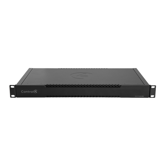
CA-10 Automation Controller
Installation Guide
Introduction
The Control4 CA-10 Automation Controller is the most powerful member of
Control4's award-winning line of controllers, designed to provide the speed,
memory, and reliability required to power the most demanding projects. The
CA-10 raises the bar for home automation through:
•
A powerful processor that provides great performance for the largest
projects.
•
Redundant internal power supplies to reduce failures due to a power spike or
brown out.
•
Dual solid state drives (SSD) with data replication to safeguard the
customer's project and customizations.
•
SSDs that are accessible behind a magnetically attached front panel for
effortless service.
•
Dual network interface controllers to protect against switch, cable, or other
network failures.
•
Redundant cooling fans to ensure quiet, worry-free performance.
•
5 year warranty, included.
Box contents
•
CA-10 Automation Controller
•
Power cord
•
Rack ears (2) attached
•
Cable ferrite clamps (2)
Specifications
Model number
C4-CA10
Network
2 × Ethernet—10/100/1000BaseT (redundant connections)
Storage
Dual 32 GB (minimum) solid-state drives (SSD) in RAID 1
configuration
USB port
2 USB 3.0 ports-1A
Power requirements
AC power supply accepts 100-240V ~ 50-60 Hz (1A)
Power supplies
2 redundant power supplies with auto failover
Power consumption
Max 70W (239 BTU/hr)
Operating temperature
32 ˚F to 104 ˚F (0 ˚C to 40 ˚C)
Storage temperature
4 ˚F to 158 ˚F (-20 ˚C to 70 ˚C)
Fans
2 redundant fans
Fan dB level
Max: 44 dB
Dimensions (W × D × H)
17.5
Weight
9.55 lb (4.33 kg)
Shipping weight
12 lb (5.44 kg)
Minimum OS version
Requires Control4 Smart Home OS 3.1 or newer
Connections
Power
Miscellaneous
×
×
×
×
10.125
1.72" (444
258
44 mm)
Warnings
Caution! To reduce the risk of electrical shock, do not expose this
apparatus to rain or moisture.
AVERTISSEMENT ! Pour réduire le risque de choc électrique, n'exposez
pas cet appareil à la pluie ou à l'humidité.
Caution! In an over-current condition on USB, the software disables
the output. If the attached USB device does not appear to power on,
remove the USB device from the controller.
AVERTISSEMENT ! Dans une condition de surintensité sur USB le
logiciel désactive la sortie. Si le périphérique USB connecté ne semble
pas s'allumer, retirez le périphérique du contrôleur.
For more information, visit the Products pages at dealer.control4.com.
Additional resources
The following resources are available for more support.
•
Control4 Knowledgebase:
kb.control4.com
•
Dealer Forums:
forums.control4.com
•
Control4 Technical Support:
•
Control4 website:
www.control4.com
•
Composer Pro documentation in online help or PDF format available on the
Dealer Portal under Support:
Front view
D
A
Caution LED—The RGB status LED gives system status feedback. See
"Troubleshooting" in this document for LED status information.
B
Link LED—The blue LED indicates that the controller has been identified in a
Control4 Composer project and is communicating with Director.
C
Power LED—The blue LED indicates that AC power is connected. The
controller turns on immediately after power is applied to it.
D
SSD LEDs—The red LED indicates an error with the SSD. See "Troubleshooting"
in this document for LED status information. The SSD LEDs are only visible
when or when the covered is removed.
Back view
A A
B C
A
Power port—AC power receptacle for an IEC power cord.
B
ID button—Button used to identify the device in Composer Pro and reset the
controller. The ID button on the CA-10 is also an LED that displays feedback
useful during a factory restore. See "Troubleshooting" in this document.
C
Reset button—Button used to factory reset the controller. See
"Troubleshooting" in this document.
D
USB—Two USB 3.0 ports for external USB drives (e.g., FAT32-formatted
devices). See "Setting up external storage devices" in this document.
E
ETHERNET—Two 10/100/1000 redundant Ethernet ports for local network
connection. See "Connecting the controller" in this document. These two ports
do not function as an Ethernet switch.
Installing the controller
Requirements:
•
Ensure that the Ethernet network is in place before starting system setup.
•
The controller requires two Ethernet network connections. When both are
connected, the controller communicates with other IP devices in the home
and access Control4 system updates over a redundant network connection.
•
Composer Pro software version 3.1.0 or newer is required for configuration.
Mounting options:
•
In-rack—The controller can be mounted in a standard equipment rack (1U).
Insert the controller into the rack space and secure it with 4 standard rack
screws (not included). Make sure the controller has adequate ventilation
(vents are on the front and back of the controller).
•
Cabinet or shelf—The controller can be installed on a shelf or other hard
surface. Make sure the controller has adequate ventilation (vents are on the
front and back of the controller).
dealer.control4.com/dealer/support
ctrl4.co/docs
A A A B A C
CA
D
E
CA-10
Controller
Advertisement
Table of Contents

Subscribe to Our Youtube Channel
Related Manuals for Control 4 CA-10


Summary of Contents for Control 4 CA-10
- Page 1 Power port—AC power receptacle for an IEC power cord. ID button—Button used to identify the device in Composer Pro and reset the Connections controller. The ID button on the CA-10 is also an LED that displays feedback Network 2 × Ethernet—10/100/1000BaseT (redundant connections) useful during a factory restore.
- Page 2 6 Insert the new SSD into the mounting slot, and while holding the SSD against the controller, replace the screw. Boot complete 7 Power on the CA-10. The SSD and Caution LEDs will flash while the RAID is rebuilding. Connected to Director/...
Need help?
Do you have a question about the CA-10 and is the answer not in the manual?
Questions and answers