Control 4 HC-250 Installation Manual
Control4 hc-250 controller
Hide thumbs
Also See for HC-250:
- Installation manual (7 pages) ,
- Quick start manual (2 pages) ,
- User manual
Table of Contents
Advertisement
Quick Links
HC-250 Controller
Installation Guide
Supported Model
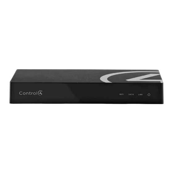
• C4-HC250-BL – HC-250 Controller, Black
Introduction
The Control4® HC-250 Controller (HC-250) provides
ways to control lights, home theaters, distributed
audio and video systems, and other devices
controlled by Infrared (IR), IP, Serial, Contact, or Relay
connections. The Controller has a fast processor,
built-in WiFi, HDMI for audio and video, improved
ZigBee radio, and is perfect for smaller systems!
The HC-250 also provides extensive media
management for audio and video content: CDs,
DVDs, and Blu-ray Discs, or digital media stored on
connected devices. Use an external storage device
with USB or NAS connectivity which supports multi-
zone audio capabilities, sending music to various
rooms throughout the home. The HC-250 fits easily
behind a TV, stacked with AV devices, or mounted on
a rack using the Rack Mount Kit (sold separately).
After you install and configure the HC-250 (using the
Composer Pro software) along with other system
components, your customers can control their
system using the On-Screen Navigator, MyHome
apps, System Remote Controls, Touch Screens, or
any other Control4-supported interface devices (sold
separately).
™
Box Contents
The following items are included in the HC-250 box:
• HC-250 Controller
• AC power cord
• IR emitters (4)
• Universal Television Mounting Plate
• Screws (4)
Accessories Available for Purchase
• Rack Mount Kit (C4-1URMK1B-B or C4-
1URMK2B-B)
• Serial Cable Kit (C4-CBL3.5MM-DB9)
Warnings
WARNING!
To reduce the risk of electrical
shock, do not expose this apparatus to rain or
moisture.
AVERTISSEMENT!
choc électrique, n'exposez pas cet appareil à la
pluie ou à l'humidité.
CAUTION:
In an over-current condition on
USB or contact output the software disables
the output and then blinks the power LED for
10 seconds. When a USB overcurrent fault is
detected, you will see the power light blink the
LED five (5) times per second, and then when
a contact overcurrent fault is detected, you will
see the power light blink the LED 12 times a
second. After the 10-second blinking period is
over the over-current circuit will be re-enabled.
If the over-current condition remains, then the
same sequence will repeat itself.
ATTENTION :
Dans une condition de
surintensité sur USB ou sortie de contact le
logiciel désactive sortie, puis le DEL Power
clignote pendant 10 secondes. Quand une
erreur de condition de surintensité sur USB
est détectée, vous verrez le DEL Power
clignoté le DEL (5) fois par seconde et puis
quand un défaut de condition de surintensité
sur contact est détecté, vous verrez le DEL
clignoté 12 fois par seconde. Après la période
de 10 secondes de clignotement, le circuit de
sur-courant sera réactivé. Si la condition de
Pour réduire le risque de
1
Advertisement
Table of Contents

Related Manuals for Control 4 HC-250


Summary of Contents for Control 4 HC-250
-
Page 1: Box Contents
Box Contents ™ The following items are included in the HC-250 box: • HC-250 Controller • AC power cord HC-250 Controller • IR emitters (4) • Universal Television Mounting Plate Installation Guide • Screws (4) Accessories Available for Purchase • Rack Mount Kit (C4-1URMK1B-B or C4- 1URMK2B-B) • Serial Cable Kit (C4-CBL3.5MM-DB9) -
Page 2: Additional Resources
• Composer documentation in online help or PDF Ethernet or WiFi network should be installed format available on the Dealer portal prior to starting the HC-250 installation. (3) The HC-250 is only compatible with PoE Front View injectors that have DC ground isolated from AC ground. -
Page 3: Back View
Audio Out (1). 3.5 mm jack for stereo channel in a rack, or stacked on a shelf. See “Wall Mount line output (line level) for amplifiers or audio Options” below if mounting the HC-250 on a wall. switches. Connect the HC-250 to the network. - Page 4 (Optional) separately). Install a standard double-gang back box allowing the screws to protrude .08” from The HC-250 provides four (4) IR ports; Ports 1 and the wall. 2 can be reconfigured independently for serial • Mount the HC-250 horizontally or vertically (see communication.
-
Page 5: Troubleshooting
Place the stick-on emitter end over the IR factory default image, perform the following steps: receiver on the Media Player, TV, or other target device to drive IR signals from the HC-250 to the Disconnect power to the HC-250. target. - Page 6 | ©2012 Control4. All rights reserved. Control4, the Control4 logo, the Control4 iQ logo and the Control4 certified logo are registered trademarks or trademarks of Control4 Corporation in the United States and/or other countries. All other names and brands may be claimed as the property of their respective owners.
Need help?
Do you have a question about the HC-250 and is the answer not in the manual?
Questions and answers