Table of Contents
Advertisement
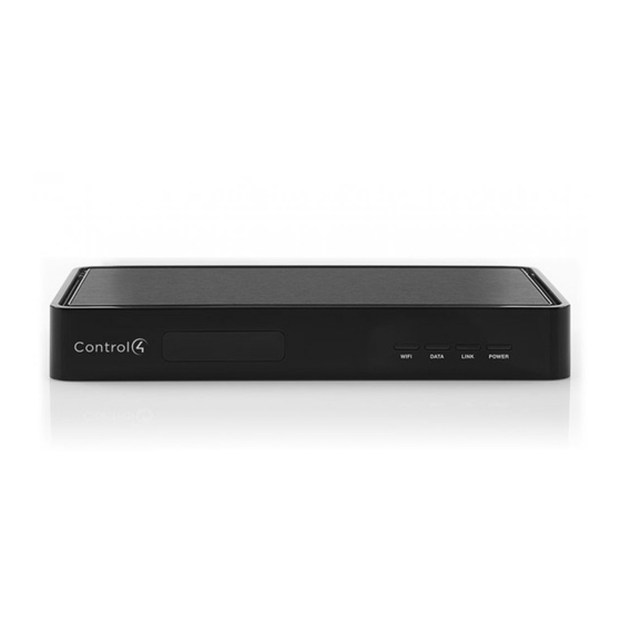
Home Controller HC-200
Installation Guide
Supported Models
C4-HC200-E-B Home Controller HC-200
C4-HC200-E-B-NR Home Controller HC-200
Introduction to Home Controller HC-200
The Control4® Home Controller HC-200 provides options for controlling
lights, home theaters, distributed audio systems, distributed video systems,
and other devices controlled using various protocols, such as Infra Red (IR)
and Serial (see IR Out description).
It provides extensive media management services for audio and video
sources, such as CDs and DVDs stored in connected devices. It also allows
you to use an external storage device with USB support for media storage. It
also includes multi-zone audio capabilities, sending music to rooms
throughout the home.
When the Controller and other system components are installed and
configured, your users can control the system using a number of interfaces,
such as the two included with this Controller: On-screen Navigator and a
System Remote Control (sold separately with C4-HC200-E-B-NR).
For more information, refer to the
End-user Documentation CD included with this device.
What's in the Box
The following are included in your Home Controller box:
• Home Controller HC-200
• System Remote Control SR-150 and 4 AAA batteries (the SR-150 is sold
separately with C4-HC200-E-B-NR)
• AC to DC power adapter with power cord
• IR emitters (4)
• Universal Mounting Plate
• Screws (4)
• Control4 End-user Documentation CD
• Home Controller HC-200 Installation Guide (this document)
Accessories Available for Purchase
• USB WiFi Adapter (C4-NWA-11G-USB)
• Rack-Mount Kit (C4-1URMK1-B)
• Serial Cable Kit (C4-CBL3.5MM-DB9)
Important Safety Instructions
1. Read these instructions.
2. Keep these instructions.
3. Heed all warnings.
4. Follow all instructions.
5. Do not use this apparatus near water.
6. Clean only with dry cloth.
7. Install in accordance with the manufacturer's instructions.
8. Do not install near any heat sources such as radiators, heat registers,
stoves, or other apparatus (including amplifiers) that produce heat.
9. Protect the power cord from being walked on or pinched particularly at
plugs, convenience receptacles, and the point where they exit from the
apparatus.
10. Only use attachments/accessories specified by the manufacturer.
11. Unplug this apparatus during lighting storms or when unused for long
periods of time.
12. Refer all servicing to qualified service personnel. Servicing is required
when the apparatus has been damaged in any way, such as power-sup-
ply cord or plug is damaged, liquid has been spilled or objects have fallen
into the apparatus, the apparatus has been exposed to rain or moisture,
does not operate normally, or has been dropped.
WARNING! To reduce the risk of electrical shock, do not expose this
apparatus to rain or moisture.
AVERTISSEMENT! Pour réduire le risque de choc électrique,
n'exposez pas cet appareil à la pluie ou à l'humidité.
WARNUNG! Um das Risiko des elektrischen Schlages zu verringern,
setzen Sie diesen Apparat nicht Regen oder Feuchtigkeit aus.
®
Control4
Supported Devices
Control4 devices that communicate with this Controller include:
Touch Screens—All types and sizes
Multi Channel Amplifiers
(such as handheld, table top, and wall-
4-Zone Amplifiers
mounted, or 10", 7", and mini)
Multi Tuners (V1 or V2)
LCD Keypads
Wireless Dimmers
Wireless 2, 3, & 6 Button Keypads
Wireless Switches
Wireless Thermostats
Wireless Outlet Dimmers
®
Wireless Outlet Switches
Speaker Points
Audio Matrix Switch
For a more information, refer to "Products" at http://www.control4.com.
Requirements and Specifications
• If you are using the Ethernet networking option, the Ethernet network
should be in place prior to starting the installation.
• If you are using the WiFi networking option, you must install and set up
the WiFi adapter (sold separately) in order to complete the installation.
• Software required for configuration is Composer Pro or an alternative
®
(less flexible) Control4
setup program, such as Easy Setup Program.
The Home Controller HC-200 specifications include:
Model Number
• C4-HC200-E-B
Network Support
• Ethernet—required (included)
• WiFi--optional, requires a WiFi adapter (sold
separately)
Media Recognition
• AMG online CD/DVD recognition and media
information service
Audio Playback Formats • MP3: 32kbps to 320kbps, CBR and VBR
Display
• LED indicators
Power Requirements
• 100-240 VAC, 60/50 Hz, 0.50 A MAX
Dimensions
• H x W x D: 1.44" (36.5 mm) x 8.55 (217 mm) x
5" (127 mm) (with connectors and mounting
plate)
Weight
• 1.8 lbs/0.82 kg
Additional Resources
The following resources are available to provide you with additional support.
• Your Control4 Reseller
• Control4 Web Site:
http://www.control4.com
• Composer online help
Front View
1
2
3
4
5
1. IR Window / IR Blaster—For capturing third-party IR codes from hand-
held devices (such as remote controls) or blasting IR codes. The WiFi
LED blinks red when capturing IR codes.
2. WiFi LED—This LED blinks orange and then blue during the boot pro-
cess. When the operating system is running, the WiFi driver changes the
LED color depending on the signal strength of its connection to its asso-
ciated access point. Colors and signal strength are as follows: orange =
Fair to Good, blue = Excellent, and no light = No connection.
3. Data LED—This blue LED indicates streaming audio is received.
4. Link LED/Identification button—Blue LED light indicates that the Home
Controller has been identified in a Control4 Composer project. Press this
button to identify this device in Composer.
5. Power LED—Blue LED light indicates AC power is present. It turns on
immediately after the power is applied to the device.
Back View
1
2
3
4
5
6
1. Audio In (1)—3.5 mm jacks for stereo channel input (line level) for one
stereo analog source.
2. Audio Out (1 left-right pair)—RCA jacks for stereo channel line output
(line level) for amplifiers or audio switches.
3. Video Out—Composite RCA and Component RCA jacks.
4. Serial Port (up to 2) or IR Out (up to 4)—3.5 mm jacks for up to 4 IR
emitters or for a combination of IR emitters and serial devices (up to 2).
Jacks 1 and 2 can be configured independently for serial devices, such
as receivers or disk changers (requires serial cable, sold separately.)
5. USB (1 port)—For external storage device with USB support (such as
FAT32 formatted devices) or WiFi adapter (C4-NWA-11G-USB).
6. Ethernet—RJ-45 jack for a 10/100 Base T Ethernet connection.
7. Power plug port—DC power supply port.
Install the HC-200
To install this controller:
1. Ensure that your home network is in place before starting your sys-
tem setup: The Home Controller HC-200 requires a network connection
(wired or WiFi) to use all features as designed. When connected, the
Home Controller can access Web-based media databases and Control4®
system updates.
2. Connect the HC-200 controller to the network: To connect using an
Ethernet connection, plug the data cable from the home network connec-
tion into the Home Controller RJ-45 port (labeled "Ethernet") and the net-
work port on the wall or at the network switch.
NOTE: To connect using the optional USB WiFi adapter (C4-NWA-11G-
USB), refer to the installation instructions shipped with the adapter.
Only use the power supply included in this box.
3. Power up the controller: Plug the DC power supply into the Home Con-
troller power plug port and an electrical outlet.
4. Connect system devices: As described in the "Connect Devices" sec-
tion that follows.
Mount the HC-200 on a Wall (Optional)
1. Mount the HC-200 horizontally using 1 standard single-gang wall
box: The wall mounting plate has 4 horizontal sets of slots. Install a sin-
gle-gang wall box. Leave the screws protruding .08" from the wall.
Mount the HC-200 horizontally or vertically using 1 standard double-
gang box: Install a standard double-gang box. Leave the screws
protruding .08" from the wall.
Mount the HC-200 horizontally or vertically using 4 screws (not pro-
vided) placed directly into a wall stud or studs: Using the mounting
plate as a template, screw 4 screws into a stud to align with the 4 center
slots for vertical positioning or into 2 studs to align with the 4 corner slots
for horizontal positioning. Leave the screws protruding .08" from the wall.
NOTE: To quickly check the fit of the screws, place the wall mounting plate
over the screws before attaching it to the bottom of the Controller.
slots for mounting
controller horizontally
holes for
attaching plate
to controller
slots for
mounting
controller
vertically
2. Use the 4 screws (provided) to attach the mounting plate to the bottom of
the Controller. Ensure that the narrow end of the slots will be on top when
the device is installed.
3. Arrange the wires to fit in the wire channels on the mounting plate.
4. Line the slots on the mounting plate up with the screws.
5. Press the device onto the screws and slide down until the screws are in
the narrow end of the slots.
7
Configure the HC-200
Configure Video Output Mode
The default video output mode is NTSC over composite. In this mode, some
bleed-through of the NTSC signal on the component video output
connections occurs. However, the video image will not appear correctly in
this mode. The HC-200 can be configured to output over component using
NTSC (standard definition) or 720p (high definition). To configure the video
mode to use the component video outputs, make the appropriate bindings for
the desired video output mode in Composer.
Connect Devices
NOTE: You can use the Composer software to step through the connection
process before or after the physical connections are complete.
Connect all applicable devices to the Home Controller HC-200 using one of
the connection options described in the following table.
Table 1. Connection Options
Audio In (1)—3.5 mm jacks for stereo channel input (line level) for 1 stereo
analog source.
Audio Out (1 left-right pair)—RCA jacks for stereo channel line
output (line level) for amplifiers or audio switches.
Video Out Options—Composite or Component
port for displaying navigation menus on a monitor
or TV. The Component jack is used for displaying
standard or high-definition video.To display stan-
dard definition video, use the Composite port.
Serial Port (up to 2) or IR Out (up to 4)—3.5 mm
jacks for up to 4 IR emitters or for a combination of
IR emitters and serial devices (up to 2). Jacks 1 and
2 can be configured independently for serial devices, such as receivers or disk
changers. See "Set Up IR Emitters or IR Blaster" for more information.
USB (1 port)—For external storage device with USB support (such as FAT32
formatted devices). See "Using External Storage Devices" for more informa-
tion or for connecting the optional WiFi adapter C4-NWA-11G-USB.
Ethernet—RJ-45 for a 10/100 BaseT Ethernet connection
Power plug port—For use with the DC power supply
(provided)
Advertisement
Table of Contents

Related Manuals for Control 4 C4-HC200-E-B


Summary of Contents for Control 4 C4-HC200-E-B
- Page 1 Controller: On-screen Navigator and a Table 1. Connection Options Install the HC-200 System Remote Control (sold separately with C4-HC200-E-B-NR). Requirements and Specifications Audio In (1)—3.5 mm jacks for stereo channel input (line level) for 1 stereo...
- Page 2 Connect the IR Ports/Serial Ports (Optional) This product has been designed and tested to the following U.S., Canadian, European, Australian, and New Zealand standards. The HC-200 provides 4 IR ports; Jacks 1 and 2 can be reconfigured independently for serial communication. Any jack not used for serial can be North America used for IR.
Need help?
Do you have a question about the C4-HC200-E-B and is the answer not in the manual?
Questions and answers