Table of Contents
Advertisement
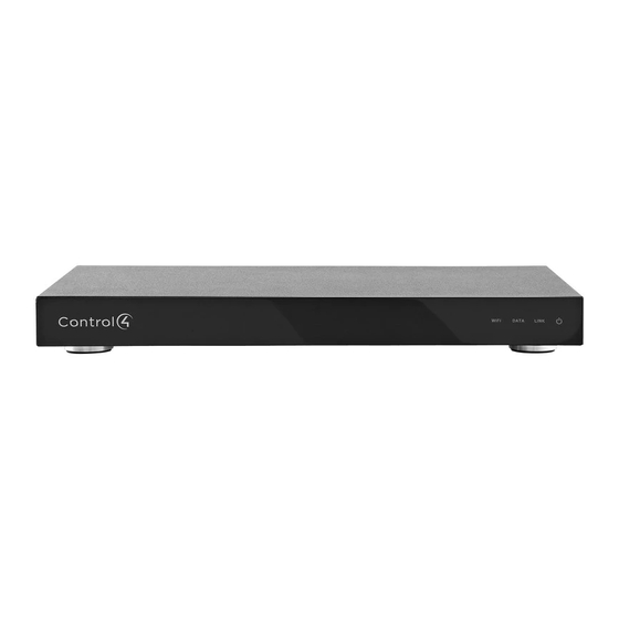
HC-800 Controller
Installation Guide
Supported Model
• C4-HC800-BL – HC-800 Controller, Black
Introduction
The Control4® HC-800 Controller (HC-800) provides
ways to control lights, home theaters, whole-
home music and video systems, and other devices
controlled by IP, infrared (IR), Serial, Contact, or Relay
connections. The Controller has a fast processor,
built-in WiFi, HDMI for audio and video, improved
ZigBee radio, and more.
The HC-800 also provides extensive media
management support for audio and video content,
including CDs, DVDs, Blu-ray Discs, or digital media
stored in connected devices. You can use an external
storage device with USB, NAS, or eSATA connectivity,
and it supports multi-zone audio capabilities, sending
music to various rooms in the home. The device can
be stacked with AV devices or rack-mounted using
the optional rack ears.
After you install and configure the HC-800 (using
the Composer Pro software) along with the other
system components, your customers can control their
system using the On-Screen Navigator, the MyHome
app, System Remote Controls, Touch Screens, or any
other Control4-supported interface devices (sold
separately).
Box Contents
™
The following items are included in the HC-800 box:
• HC-800 Controller
• AC to DC power adapter with power cord
• IR emitters (6)
• Antennas (3): ZigBee (1) and dipole antennas (2)
• Pluggable Contact/Relay connectors (2)
• Warranty Card
Accessories for Purchase
• Rack Ear Kit (C4-1UREK-B)
• 10' Antenna Kit (C4-AK-3M)
Warnings
For general information about the product, see the
Product pages at http://www.control4.com.
Requirements and Specifications
Prior to installing the HC-800, ensure that Ethernet
network wiring is in place. If you're using WiFi, see
"Antenna Considerations" which includes information
for wireless (WiFi).
WARNING!
To reduce the risk of electrical
shock, do not expose this apparatus to rain or
moisture.
AVERTISSEMENT!
Pour réduire le risque de
choc électrique, n'exposez pas cet appareil à la
pluie ou à l'humidité.
WARNING!
This CLASS I apparatus must
be connected to an AC mains socket outlet
that has a protective earthing connection
(e.g., third-prong ground conductor). DO
NOT DEFEAT THE PROTECTIVE EARTHING
CONNECTION!
AVERTISSEMENT!
Cette appareil de classe I
doit être raccordé à une prise de courant qui
a une connexion Mise à la terre (par exemple,
conducteur avec troisième broche). NE PAS
DÉFAIRE LA CONNEXION DE MISE À LA
TERRE!
1
Advertisement
Table of Contents

Subscribe to Our Youtube Channel
Related Manuals for Control 4 HC-800


Summary of Contents for Control 4 HC-800
- Page 1 Box Contents ™ The following items are included in the HC-800 box: • HC-800 Controller • AC to DC power adapter with power cord HC-800 Controller • IR emitters (6) • Antennas (3): ZigBee (1) and dipole antennas (2) Installation Guide for wireless (WiFi).
- Page 2 Back View The available current for 12V contact outputs is 1.25A maximum, shared across all outputs. Connect all applicable devices to the HC-800 using Relays AC - 36V, 2A DC - 24V, 2A the connection options described next. Maximum operation (low voltage) Dimensions H x W x D: 2.80”...
- Page 3 17 Power. For troubleshooting purposes only. After “Connect the Serial Ports” for information. plugging in the HC-800, it it does not power on, IR Out. 3.5 mm jacks for up to six (6) IR output insert a paper clip into the pinhole to power it on.
- Page 4 Pluggable Terminal Block Connectors between +12V (Power) and SIG (Signal). Connect to the Contact Port For the Contact and Relay ports, the HC-800 makes use of a pluggable terminal block connector—a The HC-800 provides four (4) contact ports for the removable plastic part that locks in individual wires pluggable terminal block provided.
- Page 5 HC-800. Figure 7. Relay Port, Normally Open Place the stick-on emitter end over the IR receiver on the Blu-ray player, TV, or other target device to drive IR signals from the HC-800 to the RELAYS target. CONTACTS...
- Page 6 Composer Information Attach one (1) of the antennas provided to the HC- 800 RSMA connector labeled ‘ZigBee’ as needed. If the HC-800 is mounted in a metal rack, use the Driver. Choose the Home Controller HC-800 • optional 10’ Antenna Kit (C4-AK3M, sold separately).
-
Page 7: Troubleshooting
Limited 2-year Warranty. Go to http://www.control4. Insert one (1) end of a paper clip into the small com/warranty for details. hole on the back of the HC-800 that is labeled About This Document ‘Factory Restore.’ Hold the button until the WiFi Status LED blinks Orange, and then release it.
Need help?
Do you have a question about the HC-800 and is the answer not in the manual?
Questions and answers