
Subscribe to Our Youtube Channel
Related Manuals for SystemAir Danvent TIME


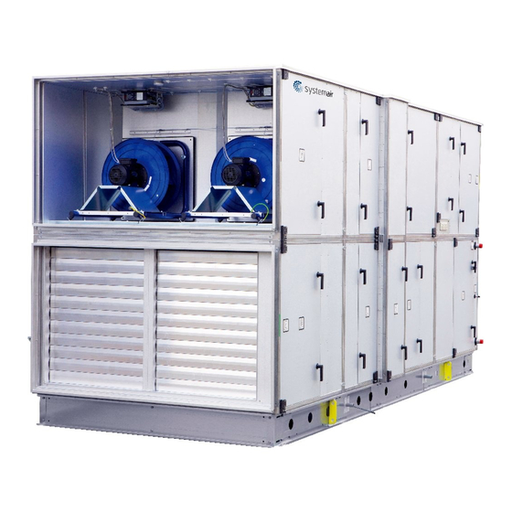
Summary of Contents for SystemAir Danvent TIME
- Page 1 July 2014 Annex 4–12 for the User Manual Air handling units Danvent TIME and Danvent DV With control system Version 1.01.04 Master for translated versions of annex 4‐12 Original version for this air handling unit ...
- Page 2 Overview Annex 4 – 12 for the User Manual version 1.01.04 is printed in this separate manual Annex 4 Assembly of base frame – height 150 mm for unit sizes 10 – 40 Annex 5 Assembly of base frame – height 150 mm for unit sizes 50 – 150 Annex 6 Assembly of base frame – height 250 mm for unit sizes 10 – 40 Annex 7 Assembly of base frame – height 250 mm for unit sizes 50 – 150 Annex 8 Installation of steel roof in the sizes 10‐150 Annex 9 Rotary exchanger – speed control and assembly of divided rotor Annex 10 Internal controller in the cooling compressor units – DVU and DVU‐C Annex 11 Menu for internal controller in the cooling compressor units ‐ DVU and DVU‐C Annex 12 Connection of fan motor and set‐up manual for Danfoss frequency converter Annex 1 – 3 for the User Manual printed on separate pages delivered with the unit Annex 1 Declaration of conformity with production number Annex 2 Technical data – unique data for every unit Annex 3 Spare part lists Annex 13 for the User Manual printed on separate pages delivered with the unit Annex 13 Commissioning protocol ‐ proposal A DVD is delivered with every unit. On this DVD is a Word‐file of the commissionning protocol – proposal for modification by the installer. If the unit is delivered with control system the annexes 14 – 16 about the control system are written on separate pages and delivered with the unit. Annex 14 Report with data from final functional test on the Systemair factory Annex 15 Short descriptions of main components in the control system Annex 16 Wiring diagram If the unit is delivered with control system the annex 17 – the Operator’s guide is written on separate pages and delivered with the unit. Annex 17 Operator’s guide (how to use the Systemair control panel) A separate manual on 12 pages delivered with every unit. This manual assists the everyday user/operator about how to control the unit by navigating the menus by the buttons and the display. 2 ...
-
Page 3: Table Of Contents
8.7 Foam bands between roof plates ........................ 8—6 8.8 Mount roof plates – some of them are overlapping by 2 ribs................ 8—6 8.9 Mount overhang profile – G5 on the other end of the unit. ................ 8—6 8.10 Mount side profiles and corners along the edges of the roof to protect persons ........... 8—7 8.11 Apply sealing on plate joints to ensure water resistance. ................ 8—7 ANNEX 9. SPEED CONTROL FOR ROTOR AND ASSEMBLY OF DIVIDED ROTOR ..9—1 9.1 Speed control .............................. 9—1 9.1.1 Selection of correct signal via the 4 DIP switch levers ............... 9—1 9.1.2 Indication of operation mode via red and green LED as well as test of motor ........ 9—2 9.1.3 Copy of the label with information about connection of cables ............ 9—3 9.2 Assemble the Systemair casing for DV60, DV80, DV100, DV120 og DV150 ............ 9—4 9.3 Assemble divided rotor for DV 60, DV 80, DV 100, DV 120 og DV 150 .............. 9—8 9.4 Assemble divided rotor for DV 190 og DV 240 .................... 9—19 9.5 Installation of motor that turns rotor and sensor for rotation ................ 9—31 3 ... - Page 4 ANNEX 10. INTERNAL CONTROLLER IN THE COOLING COMPRESSOR UNITS ..10—1 10.1 DVU – section (cooling unit) ........................... 10—1 ................................... 10—1 10.2 DVU‐internal controller for the cooling compressor system ................. 10—2 10.3 Background illumination of the display ...................... 10—2 10.4 Potentiometer on the internal controller for the cooling compressor system .......... 10—2 10.5 Selection of menu............................ 10—2 10.6 Change parameters ............................ 10—2 10.7 Menu – drawing of the menu to guide the user .................... 10—3 10.8 The start display ............................. 10—3 10.9 Settings ................................ 10—3 10.10 Automatic resets of the high pressure switch .................... 10—3 10.11 Polarity ................................. 10—3 10.12 Hotgas – setting of period .......................... 10—3 10.13 Limiter ................................ 10—3 ...
- Page 5 Annex 4. Assemble base frames – height 150 mm for units sizes 10‐40 = Corner = Splice = Length profile = Width profile Bilag 4—1 ...
- Page 6 4.1 Base frame length 720 – 2420 [mm] Unit size 10‐40 Width profile type D Unit size Quantity Length [mm] DV‐10 876 DV‐15 1026 DV‐20 1176 DV‐25 1326 DV‐30 1476 DV‐40 1626 C A Frame length [mm] Quantity Length [mm] Quantity 700‐770 2 4 ...
- Page 7 4.2 Base frame length 2420 – 4590 [mm] Unit size 10‐40 Width profile type D Unit size Quantity Length [mm] DV‐10 876 DV‐15 1026 DV‐20 1176 DV‐25 1326 DV‐30 1476 DV‐40 1626 ...
- Page 8 4.3 Base frame length 4590 – 6200 [mm] Unit size 10‐40 Width profile type D Unit size Quantity Length [mm] DV-10 DV-15 1026 DV-20 1176 DV-25 1326 DV-30 1476 DV-40 1626 C1 ...
-
Page 9: Annex 4. Assemble Base Frames - Height 150 Mm For Units Sizes 10-40
Annex 5. Assemble base frames – height 150 mm for units sizes 50‐150 = Corner = Splice = Spacer = Length profile = Spacer profile = Width profile Bilag 5—1 ... - Page 10 5.1 Base frame length 720 – 2420 [mm] Unit size 50‐DV150 Width profile type F Unit size Quantity Length [mm] DV-50 2020 DV-60 2170 DV-80 2170 DV-100 2370 DV-120 2590 DV-150 2890 ...
- Page 11 5.2 Base frame length 2420 – 4590 [mm] Unit size 50‐150 Width profile type F Width profile type E Unit size Quantity Length [mm] Length [mm] DV-50 2020 DV-60 2170 1015 DV-80 2170 1015 DV-100 2370 1115 DV-120 2590 1225...
- Page 12 5.3 Base frame length 4590 – 6200 [mm] Unit size 50‐150 Width profile type F Width profile type E Unit size Quantity Length [mm] Length [mm] DV-50 2020 DV-60 2170 1015 DV-80 2170 1015 DV-100 2370 1115 DV-120 2590...
- Page 13 Annex 6. Assemble base frames – height 250 mm for units sizes 10‐40 = Corner = Splice = Length profile = Spacer profile = Width profile Bilag 6—1 ...
- Page 14 6.1 Base frame length 720 – 2420 [mm] Unit size 10‐40 Width profile type E Unit size Quantity Length [mm] DV-10 DV-15 1020 DV-20 1170 DV-25 1320 DV-30 1470 DV-40 1620 ...
-
Page 15: Base Frame Length 2420 - 4590 [Mm] Unit Size 50-150
6.2 Base frame length 2420 – 4590 [mm] Unit size 10‐40 Width profile type E Spacer profile type D Unit size Quantity Length [mm] Length [mm] DV-10 DV-15 1020 1020 DV-20 1170 1170 DV-25 1320 1320 DV-30 1470 1470... -
Page 16: Base Frame Length 4590 - 6200 [Mm] Unit Size 50-150
6.3 Base frame length 4590 – 6200 [mm] Unit size 10‐40 Width profile type E Spacer profile type D Unit size Quantity Length [mm] Length [mm] DV-10 DV-15 1020 1020 DV-20 1170 1170 DV-25 1320 1320... -
Page 17: Annex 6. Assemble Base Frames - Height 250 Mm For Units Sizes 10-40
Annex 7. Assemble base frames – height 250 mm for units sizes 50‐150 = Corner = Splice = Splice = Spacer = Length profile = Spacer profile = Width profile Bilag 7—1 ... -
Page 18: Base Frame Length 720 - 2420 [Mm] Unit Size 10-40
7.1 Base frame length 720 – 2420 [mm] Unit size 50‐150 Width profile type G Unit size Quantity Length [mm] DV-50 1920 DV-60 2070 DV-80 2070 DV-100 2270 DV-120 2490 DV-150 2790 ... -
Page 19: Base Frame Length 2420 - 4590 [Mm] Unit Size 10-40
7.2 Base frame length 2420 – 4590 [mm] Unit size 50‐150 Width profile type G Spacer profile type F Unit size Quantity Length [mm] Length [mm] DV-50 1920 DV-60 2070 1010 DV-80 2070 1010 DV-100 2270 1110 DV-120 2490... -
Page 20: Base Frame Length 4590 - 6200 [Mm] Unit Size 10-40
7.3 Base frame length 4590 – 6200 [mm] Unit size 50‐150 Width profile type G Spacer profile type F Unit size Quantity Length [mm] Length [mm] DV-50 1920 DV-60 2070 1010 DV-80 2070 1010 DV-100 2270 1110 DV-120 2490... -
Page 21: Annex 8. Installation Of Steel Roof In The Sizes 10-150
Annex 8. Installation of steel roof in the sizes 10‐150 8.1 Overview Mount rails A1, B2, C3, D4, E5 on the unit for support of trapezoidal roof plates (mount also rails Y and Z on units of the size 30 and on units that are larger than size 30 longitudinally at the centre‐ line of the units). Place foam bands – P – on the horizontal rails A1, B2, C3 and D4 for support of roof plates. Calculate overhang of the roof at both ends of the unit and mount roof overhang profile – G1 on the first trapezoidal roof plate – F1 before the roof plate is mounted. Place and mount roof plates F1, F2, F3 and so on. Remember foam bands on the side laps between roof plates to prevent rainwater from passing through. Place roof overhang profile – G5 at the other end of the unit before the last roof plate is mounted. Mount sides and corners on the roof. Apply sealing where plates are joined to ensure water resistance ‐ even in stormy weather. Bilag 8—1 ... -
Page 22: Mount Rails. Units Of Size 10, 15, 20, And 25
8.2 Mount rails. Units of size 10, 15, 20, and 25 Squeeze sealant in sufficient quantity between the underside of the rails A1, B2, C3, D4, E5 and the horizontal top side of the unit before the rails are mounted. This means that the rails are standing on sealant to achieve the tightest connection between rails and unit to prevent rainwater from passing under the rails and into the unit. Mount the rails A1 and B2 on the front side (the side with the inspection doors) – use the simple self‐drilling screws without the sealing washer – see the illustration of the screw below. Note: Rail B2 fits into the rail A1, and this offers the advantage that the rail B2 can be slid inside the rail A1 to adjust the length of rail B2 accurately to the length of the unit. In this way it is not necessary to spend time and effort cutting the rail B2. Mount the lower rails C3 and D4 on the back side of the unit. Note: Rail D4 fits into the rail C3, and this offers the advantage that the rail D4 can be slid inside the rail C3 to adjust the length of rail D4 accurately to the length of the unit. In this way it is not necessary to spend time and effort on cutting the rail D4. Mount vertical rail – E5 ‐ with the roof slope at each end of the unit It is important to place a screw in each hole – even though the number of holes for screws seems to be very large, a screw in each hole is necessary as the stress on the roof during stormy weather is extremely high. 8.3 Mount rails. Units of size 30 and units larger than size 30. On units of size 30 and on units that are larger than size 30, rails A1, B2, C3, D4, E5 must be mounted on the unit for support of trapezoidal roof plates, but also rails Y and Z must be mounted longitudinally at the centre‐line of the units to hold the trapezoidal roof plates. Squeeze sealant in sufficient quantity between the underside of the rails A1, B2, C3, D4, E5 and the horizontal top side of the unit before the rails are mounted. This means that the rails are standing on sealant to achieve the tightest connection between rails and unit to prevent rainwater from passing under Bilag 8—2 ... -
Page 23: Roof Overhang Along The Long Sides Of The Unit
the rails and into the unit. Mount the rails A1 and B2 on the front side (the side with the inspection doors) – use the simple self drilling screws without the sealing washer – see the illustration of the screw below. Note: Rail B2 fits into the rail A1, and this offers the advantage that the rail B2 can be slid inside the rail A1 to adjust the length of rail B2 accurately to the length of the unit. In this way it is not necessary to spend time and effort cutting the rail B2. Mount the lower rails C3 and D4 on the back side of the unit. Note: Rail D4 fits into the rail C3, and this offers the advantage that the rail D4 can be slid inside the rail C3 to adjust the length of rail D4 accurately to the length of the unit. In this way it is not necessary to spend time and effort cutting the rail D4. Mount vertical rail – E5 ‐ with the roof slope at each end of the unit. Mount the rails Y and Z on the unit with the centre‐line of the rails exactly over the centre‐line of the unit. It is longitudinal on the middle of the units to hold the trapezoidal roof plates. Notice, that rail Z fits over the lower rail Y, and this offers the advantage that the rail Z can be slided on the rail Y to adjust the length of rail Z accurately to the length of the unit. In this way it is not necessary to spent time and effort on cutting the rail Z. It is important to place a screw in each hole – even though the number of holes for screws seems to be very large, a screw in each hole is necessary as the stress on the roof during stormy weather is extremely high. 8.4 Roof overhang along the long sides of the unit The roof plates are longer than the width of the unit to ensure sufficient overhang along the sides of the unit. The overhang is 100 mm along each side of the smallest unit – size 10. The overhang is 150 mm along each side of the units – size 15, 20, 25. The overhang is 175 mm along each side of the biggest units – including size 30. 8.5 Calculation of the overhang at the ends of the unit. Mount overhang profile – G1. The roof must be between 200 and 400 mm longer than the length of the unit to secure a roof overhang between 100 mm and 200 mm at the each of the 2 ends of the unit, and the length of this overhang must be calculated before the first roof plate is mounted. Bilag 8—3 ... - Page 24 The unit is delivered with 2 similar overhang profiles ‐ G1 and G5 ‐ one for each end of the roof. Mount one of the 2 roof overhang profiles – G on a trapezoidal roof plate. Use the self drilling, painted screws with sealing washers ‐ W ‐ see the illustration. Note: Foam bands ‐ P – are necessary between the overhang profile G1 and the roof plate F1. See the illustration. Self‐drilling, painted screws supplied with sealing washer for the mounting of the trapezoidal plate to the roof overhang profile. The total cover width of the trapezoidal roof plates always changes with the pitch of 207 mm between the trapezoidal ribs, making up a total length of the complete roof of ‐ for example 2070 mm, 2277 mm, 2484 mm and so on. We call this length of the total roof for RL and we call the total length of the complete unit for AL. The trapezoidal roof must always be longer than the unit, to obtain a reasonable overhang called – XX ‐ of the roof at both ends. In the table below you will find 40 different lengths of roofs (always changing with the 207 mm) and the lengths of units that are ideal for each of the 40 alternative roof lengths. Bilag 8—4 ...
- Page 25 Measure the total length – AL of the unit – for example 5 metres between the 4982 and 5182 mm mentioned in the table below. AHU length Roof AHU length Roof AHU length Roof AL length AL length AL length RL RL RL 1670 – 1870 2070 4568 – 4768 4968 7466 – 7666 7866 1877 – 2077 2277 4775 – 4975 5175 7673 – 7873 8073 2084 – 2284 2484 4982 – 5182 5382 7880 – 8080 8280 2291 – 2491 2691 5189 –...
-
Page 26: Foam Bands Between Rails And Roof Plates - Mount Roof Plates
8.6 Foam bands between rails and roof plates – mount roof plates. Place foam bands P between profiles A1, B2, C3, D4 and roof plates. The trapezoidal roof plates are mounted with the self‐drilling, painted screws supplied with sealing washer. 8.7 Foam bands between roof plates Mount the self‐adhesive foam band – O ‐ on the underlapping rib for water resistant and effective sealing due to the small slope of the roof. 8.8 Mount roof plates – some of them are overlapping by 2 ribs The width of each plate is always 1.035 mm and some of the plates have to overlap by 2 ribs to achieve the optimal total length of the whole roof — see the illustration above. 8.9 Mount overhang profile – G5 on the other end of the unit. When the last trapezoidal plate (in this example F5) has been placed on the unit, the second roof overhang profile G5 must be pushed under the trapezoidal roof plate and mounted with the self‐drilling, painted screw with sealing washer. Mounting must be similar to the mounting of roof overhang profile under the trapezoidal roof plate at the other end of the unit. Bilag 8—6 ... -
Page 27: Mount Side Profiles And Corners Along The Edges Of The Roof To Protect Persons
8.10 Mount side profiles and corners along the edges of the roof to protect persons Profiles N and O with the rectangular holes are for the long and lower side of the roof because rain can escape through the holes. Mount the profiles type N first and the profile O last because the profile O goes over the profile N. Mounted in this order, the profile O can match the end of the roof and the surplus length of the profile O will just cover part of the previous profile N. Mount the profiles L and M along the long and higher front side of the roof. Mount the 4 protection corners. 8.11 Apply sealing on plate joints to ensure water resistance. Finish installation of the steel roof by sealing all plate joints with silicone to prevent rainwater from passing into the unit. See examples below of joints to be sealed. Bilag 8—7 ... - Page 28 Bilag 8—8 ...
-
Page 29: Annex 9. Speed Control For Rotor And Assembly Of Divided Rotor
Annex 9. Speed control for rotor and assembly of divided rotor 9.1 Speed control The cabinet with the speed control system for the rotor is installed behind the inspection door in the rotor section. The cabinet contains the speed controller with all components, terminal blocks, LED displaying the operation mode, the dual position DIP switch with 4 sliding levers for programming the rotor motor signal and a button for the activation of the test mode. Through the different combinations of the 4 sliding levers of this dual position DIP switch, the correct signal is available for the 3 different motors used for the 14 sizes of air handling units. The sliding levers are set and the function is checked at the factory. The positions of the levers appear from the tables below. 9.1.1 Selection of correct signal via the 4 DIP switch levers The 4 DIP switch levers Position Function Code Up Active = ON 1 Down Deactivated = OFF 0 The factory sets the positions of the 4 DIP switch levers for the maximum of 10 revolutions per minute for standard temperature exchangers and for hygroscopic exchangers. The position of each DIP switch lever is shown below. DV Diameter of DIP switch position Motor pulley 10 50 15 ... -
Page 30: Indication Of Operation Mode Via Red And Green Led As Well As Test Of Motor
The factory sets the positions of the 4 DIP switch levers for the maximum of 20 revolutions per minute for sorption exchangers. The position of each DIP switch lever is shown below. DV Diameter of DIP switch position Motor pulley 10 50 1000 90TYD‐S214‐M 2.8Nm 15 87 20 87 0100 25 107 120TYD‐S214‐M 5.5Nm 30 107 40 107 1100 50 118 60 118 80 140 1010 100 150 120 150 ... -
Page 31: Copy Of The Label With Information About Connection Of Cables
Restart of rotor: ‐ Switch off power and switch on power again or ‐ Press the test button inside the cabinet Test of motor by checking the resistance in all 3 vindings Motor sizes Ohm 90TYD‐S214‐M 40Ω 120TYD‐S214‐M 18Ω 120TYD‐S214‐L 10Ω Setting of constant speed: ‐ Set fourth DIP switch lever in position ‐ ON Test: ‐ Set fourth DIP switch lever in position – ON ‐ Press the test button 9.1.3 Copy of the label with information about connection of cables This self‐adhesive label is always placed on the cover of the cabinet. The text is always in English. Annex 9—3 ... -
Page 32: Assemble The Systemair Casing For Dv60, Dv80, Dv100, Dv120 Og Dv150
9.2 Assemble the Systemair casing for DV60, DV80, DV100, DV120 og DV150 Size DV 60 2170 1640 DV 80 2320 1790 DV 100 2520 1940 DV 120 2890 2090 DV 150 3040 2240 ... - Page 33 Annex 9—5 ...
- Page 34 A1 Size Quantity Length (mm) DV 60 1014 DV 80 1164 DV 100 1314 DV 120 1464 DV 150 1614 Annex 9—6 ...
- Page 35 B1 B5 B4 B2 B5 Size Number # DV 150 12100510 B1 B2 B4 Size Quantity # Quantity # Quantity # Quantity # DV 60 1 10122310 ‐ ‐...
-
Page 36: Assemble Divided Rotor For Dv 60, Dv 80, Dv 100, Dv 120 Og Dv 150
9.3 Assemble divided rotor for DV 60, DV 80, DV 100, DV 120 og DV 150 Annex 9—8 ... - Page 37 Annex 9—9 ...
- Page 38 Annex 9—10 ...
- Page 39 Annex 9—11 ...
- Page 40 Annex 9—12 ...
- Page 41 Annex 9—13 ...
- Page 42 Annex 9—14 ...
- Page 43 Annex 9—15 ...
- Page 44 Annex 9—16 ...
- Page 45 Annex 9—17 ...
- Page 46 Annex 9—18 ...
-
Page 47: Assemble Divided Rotor For Dv 190 Og Dv 240
9.4 Assemble divided rotor for DV 190 og DV 240 Annex 9—19 ... - Page 48 Annex 9—20 ...
- Page 49 Annex 9—21 ...
- Page 50 Annex 9—22 ...
- Page 51 Annex 9—23 ...
- Page 52 Annex 9—24 ...
- Page 53 Annex 9—25 ...
- Page 54 Annex 9—26 ...
- Page 55 Annex 9—27 ...
- Page 56 Annex 9—28 ...
- Page 57 Annex 9—29 ...
- Page 58 Annex 9—30 ...
-
Page 59: Installation Of Motor That Turns Rotor And Sensor For Rotation
9.5 Installation of motor that turns rotor and sensor for rotation Installation of rotor motor and sensor for control of rotation in DVC module after assembly of divided rotor Fig. 1 Annex 9—31 ... - Page 60 Fig.2 Fig. 2 By delivery of a DVC module with divided rotor, the motor is installed before delivery to the customer Fig.5 Fig.3 Fig.4 Fig. 3, 4 and 5 The motor and console is secured to the motor plate by 4 shock absorbers mounted by M8 bolts. Fig.6 Fig. 2 og 6 The drive belt must be placed around the rotor and in the center position of the rotor. Observe brackets for assembly of the rotor segments. Annex 9—32 ...
- Page 61 Fig. 7 and 8 . Sensor for control of rotation must be installed by the installer. The distance must be 1‐4 mm from the outmost brackets used for the assembly of the rotor segments. Fig.8 1 ‐ 4mm Fig.9 Fig. 9 Please be aware of the height of the brackets that are used for the assembly of the rotor segments. Please turn the rotor to check the sensor do not touch any of the brackets. Annex 9—33 ...
-
Page 62: Annex 10. Internal Controller In The Cooling Compressor Units
Annex 10. Internal controller in the cooling compressor units 10.1 DVU – section (cooling unit) The air handling unit section – DVU – is a separate section in the air handling unit, and the section contains a complete stand‐alone cooling compressor system. The system has been started, adjusted and optimized before the delivery. The refrigerant is evaporated directly in the cooling coil and the cooling capacity is regulated automatically and steplessly between 10 and 100 %. The system is delivered with the HFC refrigerant R‐407C in the circuit. Internally in the section a DVU‐internal controller ‐ LMC251 ‐ and complete control system take care of all safety functions as well as the frequency converter regulated compressor that creates exactly the cooling capacity ordered by the main air handling unit controller via the very common 0‐10V DC signal. When the demand for cooling occurs in the room, the main air handling unit controller sends a start signal and a signal exceeding 0 volt to the cooling compressor system. When the signal exceeds 1.5 volt the cooling compressor starts. After start‐up the capacity is regulated between 10 and 35 % by the hotgas valve (HGV in the illustration below) in on/off in sequences with the cooling compressor at the lowest number of revolutions. When more than 35 % of the cooling capacity is demanded (signal exceeds more than 3,5 volt) the hotgas valve closes, the cooling capacity is regulated by the frequency converter (FC in the illustration below) to the strictly necessary revolutions of the compressor. By declining demand with the compressor at the lowest revolutions, the hotgas valve is regulated on/off in sequences, when the demand is less than 34 %. The cooling compressor stops when the demand is less than 10 %. To avoid that the compressor stops because the high pressure switch (Hp in the illustration below) cuts off, an automatic capacity reduction system is installed. The capacity reduction system consists of a pressure transducer (P in the illustration below) installed in the high pressure pipe between the compressor and the condenser and software in the DVU‐internal controller that reduces the revolutions of the compressor to avoid that the pressure after the compressor develops to the cut‐off pressure of the high pressure switch – the system does not stop; it will always remain cooling to some extent.Air volume capacities for supply fan and for exhaust fan are not regulated by the built‐in controller – LMC251 ‐ for the cooling system, but by the main air handling unit controller. The technician from a certified installer of cooling units must agree with the installer of the ventilation system and the main air handling unit controller that the air volumes for the system are not going to exceed the maximum or to be lower than the recommended minimum mentioned below in section 3.2.5.18 in this manual Extract Supply Analog in ... -
Page 63: Dvu-Internal Controller For The Cooling Compressor System
10.2 DVU‐internal controller for the cooling compressor system Two LEDs (light diodes) are placed on the DVU‐internal controller and each of the LEDs can be on or flash green, red or orange. During normal conditions a permanent green light indicates that everything is normal, orange indicates alternative running mode while red indicates alarm. LED Off Green Green Orange Orange Red flashing flashing flashing Upper LED Off‐signal from .. On‐signal from .. main AHU main AHU controller controller Lower LED .. .. Compressor Hotgas Alarm active active Priorities of the collars are: 1. Red (highest priority) 2. Red Flashing 3. Orange 4. -
Page 64: Menu - Drawing Of The Menu To Guide The User
10.7 Menu – drawing of the menu to guide the user Drawing of the menu appears from section 12 10.8 The start display The start picture shown when the potentiometer has not been activated for 10 minutes In: nnn% shows the capacity ordered by the main air handling unit controller. Out: nnn% shows the capacity ordered by this internal controller ‐ LMC251 – of the compressor. 10.9 Settings About basic settings in the submenus in the LMC251 10.10 Automatic resets of the high pressure switch This is about the maximum number of automatic resets of the high pressure switch that are acceptable within one hour. If this number is exceeded, the unit will be shut down until the high pressure switch has been reset manually. 10.11 Polarity The Alarm polarity can be set to”Normally Open” or ”Normally Closed”. 10.12 Hotgas – setting of period This is the number of seconds that the hotgas valve is open. The period is relatively long, but the supply temperature is not oscillating at all and the stability of the supply temperature is sufficient. The number of seconds is a factory setting that should not be reduced. Reduction of the number of seconds will not improve the stability of the temperature to a degree that can be proven by measurements. If the number of seconds is reduced, the number of times that the valve is opened and closed will be increased – maybe considerably, and the valve could be worn out prematurely. 10.13 Limiter DeltaMax is the maximum acceptable change in % / second of the actual cooling capacity. 10.14 Service In this menu information about the software version in the controller as well as 2 submenus – “Manual operation” and “Runtime” 10.15 Manual operation When the menu – Manual operation ‐ is activated, the technician is able to control the operation manually, when the start signal from the main air handling unit controller is on (start signal is just potential free connection of the two terminals – 3&4). This procedure is relevant for the test during the annual maintenance with the control of all safety and regulation procedures or after installation of new components. If no new settings have been carried out on the controller for 10 minutes, the menu – Manual operation – is deactivated, and the unit returns to the automatic mode. 10.16 Running hours and hotgas activations In this menu the number of running hours for the compressor, and the number of activations of the hotgas valve can be read. This information is valuable for the maintenance. ... -
Page 65: Alarm Log
10.17.2 Alarm Log The last 15 alarms are logged and it is not possible to delete them. No time‐stamps on the stored alarms. 10.18 Modified software in Danfoss frequency converter for the compressor The standard settings in the Danfoss frequency converter have been changed in 2 menu items, because the safety functions in these menus are transferred to the DVU‐internal controller ‐ LMC251; ‐ In the menu item 5‐10 Terminal 18, digital input (start), the value must be changed from 8 to 0. ‐ In the menu item 5‐12 Terminal 27, digital input (free running inverted), the value must be changed from 2 to 0. Especially for compressor VTZ 121 in DVU 25 and DVU 30 as well as for the compressor VTZ 086 in DVU 20 In addition to the above‐mentioned modifications, the modifications below are necessary for the compressor VTZ 121 in DVU 25 and DVU 30; ‐ Value in menu item 1‐90 changed to 2 ‐ Value in menu item 1‐93 Terminal 54 changed to 2 Usually the Danfoss frequency converter keeps the change to the standard factory setting stored for ever, but if the software has been turned back to the original factory setting for some reason, the above‐ mentioned modifications must be carried. If the modifications are not carried out correctly, the compressor will not be switched on at all. 10.19 Maintenance General maintenance must be carried out according to national and local regulations by a skilled technician from a certified company. List of spare parts as well as datasheets from the manufacturers are available on the CD delivered with the unit. Air volume, cooling capacity, refrigerant content DVU‐10 DVU‐15 DVU‐20 DVU‐25 DVU‐30 DVU‐40 Width in mm 970 1120 1270 1420 1570 ... -
Page 66: Cooling Capacity And Absorbed Power Consumption In Kw For Compressor - Eer Factor
4.2 Maximum – 90 Hz 11.1/3.7 ‐ 15.7/5.4 ‐ 23.3/6.9 ‐ 33.8/11.1 ‐ 36.7/11.3 ‐ 47.3/13.2 ‐ 3.0 2.9 3.4 3.0* 3.2* 3.6 *85 Hz The minimum capacity is selected at the frequency converter output at 35 Hz (the compressor in the DVU 20, 25/30 and 40 can reduce the capacity further to even lower revolutions at 30 Hz). At the lowest revolutions the hotgas valve opens to reduce the capacity further – the lowest cooling capacity equals 10 % of the capacity at 90 Hz. If the temperature and humidity conditions on the site deviate from the above‐ mentioned conditions, accurate values can be calculated in the design programme SystemairCAD. Systemair is ready to provide you with a print‐out, if a copy of calculation of the specific unit in the SystemairCAD is not available. 10.21 Power consumption for the fans The unit section ‐ DVU ‐ is one of several sections in the air handling unit, and the supply air fan for the evaporator as well as the exhaust air fan for the condenser, heat recovery and heating coil are installed in other sections. The energy performance for the complete unit including the consumption of the fans is always calculated in the design programme SystemairCAD. Systemair is ready to provide you with a print‐ out, if a copy of the calculation of the specific unit in the SystemairCAD is not available. 10.22 Data plate The data plate for the cooling unit is mounted inside the unit section – DVU – behind one of the doors. An example of the data plate is shown below. DVU‐40 Manufaturing year Serial Number: Refrigerant 407C Quantity of refrigerant 9.8 kg ... -
Page 67: Dvu-C - Section - Cooling Unit With Cooling Recovery
10.23 DVU‐C – section ‐ cooling unit with cooling recovery The DVU‐C unit is similar the DVU unit but with the difference that condenser on the DVU‐C unit is placed in the extract air flow after the rotary heat exchanger with the advantage that the outdoor air is precooled by the rotary heat exchanger, when the extract air temperature is lower as the outdoor air temperature. Due to the reduced outdoor air temperature before the cooling coil, the electricity consumption of the cooling compressor is reduced. DVU‐C sektionen ligner DVU sektionen med den markante forskel at kondensator batteriet på DVU‐C sektionen er placeret i luftstrømmen efter den roterende veksler med den fordel, at indsuget udeluft bliver afkølet via den roterende veksler, når temperaturen på fraluften er lavere end temperaturen på den indsugede udeluft. Når temperatur på det indsugede luft er sænket nogle grader før fordamper batteriet, skal kølekompressoren yde mindre, så kølekompressorens elforbrug reduceres. Annex 10—6 ... -
Page 68: Annex 11. Menu For Internal Controller In Cooling Compressor
Annex 11. Menu for internal controller in cooling compressor Menupoint Submenu Submenu Default Comments In: nnn% Set point for capacity level Out: nnn% Actual capacity level SETTINGS MENU UP Number of automatic resets of high pressure switch AUTORES. off’s within one hour before activation of alarm. POLARITY Polarity of BMS set to “Normally Open”... -
Page 69: Annex 12. Connection Of Fan Motor And Set-Up For Frekv. Conv
Annex 12. Connection of fan motor and set‐up for frekv. conv. 12.1 Connection of fan motor Delta connection – for low speed – is shown to the left, and star connection – for high speed – is shown to the right. Annex 12—1 ... -
Page 70: Set-Up For Danfoss Fc101 For Dv-Units With Ac Motors
12.2 Set‐up for Danfoss FC101 for DV‐units with AC motors SETUP IS DONE IN FACTORY BEFORE DELIVERY To reload Systemair factory settings from the control panel: 0‐50: LCP Copy: [2] Systemair factory set‐up is based on Danfoss initialization. 14‐22: Operation mode: [2] Initialisation (Danfoss Initialisation) Turn power off and on. Systemair factory set‐up: 0‐01: Language selection: 1‐03: Torque characteristic: Single fan: [3] Auto‐Energy optim. With twin fan set‐up: [1] Variable Torque 1‐20: Motor Power: According to motor plate / order papers With twin fan set‐up total power must be used 1‐24: Motor Current: According to motor plate / order papers With twin fan set‐up total current must be used 1‐25: Motor Nominal Speed: According to motor plate / order papers 1‐42: Motor Cable Length: 3m 1‐50: Motor Magnetisation at zero speed.: 0 % 1‐52: Min. Speed Normal Magnetisation: 10 Hz 1‐73: Flying Start: [0] Disabled ... - Page 71 Annex 12—3 ...
-
Page 72: Ac-Fan Operation Without Thermistor For Danfoss Fc101
12.3 AC‐fan operation without thermistor for Danfoss FC101. Systemair factory set‐up is based on Danfoss initialization. 14‐22: Operation mode: [2] Initialisation (Danfoss Initialisation) Turn power off and on. Systemair factory set‐up: 0‐01: Language selection: 1‐03: Torque characteristic: [3] Auto‐Energy optim. 1‐20: Motor power: According to motor plate 1‐24: Motor Current: According to motor plate 1‐25: Motor Nominal Speed: According to motor plate 1‐29: Automatic motor adption (AMA): [1] Kompl.motor adaption to (Turn power off and on.) 1‐42: Motor Cable Length: Order specific 1‐50: 0 % Motor Magnetisation at zero speed.: 1‐52: 10 Hz Min. Speed Normal Magnetisation: 1‐73: Flying start: ... -
Page 73: Set-Up Danfoss Fc101 For Dv-Units With Pm Motors
12.4 Set‐up Danfoss FC101 for DV‐units with PM motors SETUP IS DONE IN FACTORY BEFORE DELIVERY To reload Systemair factory settings from the control panel: 0‐50: LCP Copy: [2] Systemair factory set‐up is based on Danfoss initialization. 14‐22: Operation mode: [2] Initialisation (Danfoss Initialisation) Turn power off and on. Systemair factory set‐up: 0‐01: Language selection: 1‐06: Clockwise Direction: [1] Inverse 1‐10: Motor Construction: [1] PM, non‐salient SPM 1‐24: Motor Current: According to motor plate / Schedule 1‐25: Motor Nominal Speed: A ccording to motor plate / Schedule 1‐26: Motor Cont. Rated torque: According to motor plate / Schedule 1‐30: Stator Resistance (Rs): According to motor plate / Schedule 1‐37: d‐axis inductance (Ld): According to motor plate / Schedule 1‐39: Motor Poles: According to motor plate / Schedule ... - Page 74 Schedule for PM motor parameters Menu: 303 + 625 414 + 419 Amp Motor Nm Motor Type Name RPM Name Ohm Bemf @ Max Number plate rated plate [Rf‐f] mH [Lf‐f] Poles 1000 Max Hz motor Hz HPS 71 3800 18 3800 3,600 13,00 HPS 71 3700 28 3700 1,580 6,10 HPS 71 3300 18 3300 5,750 20,50 HPS 71 3200 30 3200 1,850 7,25 HPS 71 2900 21...
- Page 75 ...
- Page 76 Systemair A/S Ved Milepælen 7 DK‐8361 Hasselager Tel. 0045 8738 7500 www.systemair.dk Annex 12—8 ...
Need help?
Do you have a question about the Danvent TIME and is the answer not in the manual?
Questions and answers