
Related Manuals for SystemAir Topvex TR800


Summary of Contents for SystemAir Topvex TR800
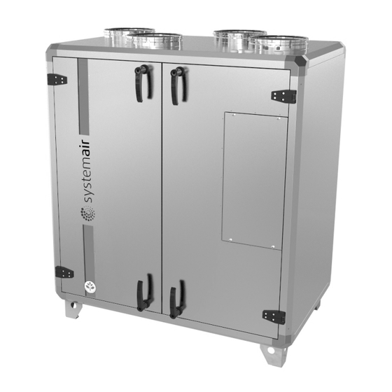
- Page 1 Topvex TR800, TR1300, TR1800, TR4000 Compact Air Handling Unit Operation and Maintenance Instructions Item# 415005 2022-05-13...
-
Page 2: Table Of Contents
2.2.5 Hydronic Heater ..........................4 2.2.6 Electrical Heater ..........................4 2.3 Internal Components - Electrical Connection Box ...................5 2.3.1 Electrical Components Topvex TR800-1800 EL ................5 2.3.2 Electrical Components Topvex TR800-1800 HW ................6 2.3.3 Electrical Components Topvex TR 4000 ..................7 3 Interface Description............................8 3.1 Control Panel ............................8... -
Page 3: Warnings
Caution • If the unit is installed in a cold place make sure that all joints are covered with insulation, and tape well 2.1 Internal Components Topvex TR800-4000 • Duct connections/duct ends should be covered during storage and installation • Do not connect tumble dryers to the ventilation system •... - Page 4 Heat exchanger. Rotor motor. Rotor belt Re-heater electric or hydronic. Pre-heater electric or water hydronic. Pressure transmitter for fan & Filter guard. Rotation guard for heat exchanger. Electrical connection box. Operation and Maintenance Instructions Topvex TR800, TR1300, TR1800, TR4000 Systemair Inc.
-
Page 5: Description Of Internal Components
A sensor registers the rotation of the heat exchanger rotor. It’s connected to the main controller which gives an alarm if the rotor stops while there is a heat demand (pos.7 figure 1). Topvex TR800, TR1300, TR1800, TR4000 Operation and Maintenance Instructions... -
Page 6: Temperature Sensors
Both hydronic pre-heater and re-heater function outputs are modulated by the unit control in order to maintain their respective air temperature set points. For Topvex TR800-4000 units without pre-heater and/or re-heater, a heating water coil can be equipped inside the unit. See “HWC-EPH Installation Instructions” manual (420353) for correct procedure. -
Page 7: Internal Components - Electrical Connection Box
2.3.1 Electrical Connection Box Topvex TR800-1800 EL Topvex TR800-1800 are equipped with a built in controller and internal wiring (Figure 3). Fig. 3 Electrical components Topvex TR800-1800 EL Table 2: Description of electrical components Topvex TR800-1800 EL... -
Page 8: Electrical Components Topvex Tr800-1800 Hw
2.3.2 Electrical Connection Box Topvex TR800-1800 HW Topvex TR800-1800 are equipped with a built in controller and internal wiring (Figure 4). Fig. 4 Electrical components Topvex TR800-1800 HW Table 3: Description of electrical components Topvex TR800-1800 HW Position Description Controller E-28 (UC) -
Page 9: Electrical Components Topvex Tr 4000
Terminals for main power voltage to the unit (TB1) Contactor (K1) On/Off rotor motor Automatic fuse (AS1) Thermal overload relay (TOR) Note: For pre-heater components, please refer to the “HWC-EPH Installation Instructions” manual (420353). Topvex TR800, TR1300, TR1800, TR4000 Operation and Maintenance Instructions Systemair Inc. -
Page 10: Interface Description
Mounting holes Connection block. Connection to yellow cable. Connection to orange cable. Connection to red cable. Connection to brown cable. Connection to black cable Operation and Maintenance Instructions Topvex TR800, TR1300, TR1800, TR4000 Systemair Inc. -
Page 11: Commissioning
Choose Language Select language by pressing OK followed by the English UP/DOWN arrow buttons. Confirm by pressing OK. Move to the next level by pressing the DOWN arrow button. Topvex TR800, TR1300, TR1800, TR4000 Operation and Maintenance Instructions Systemair Inc. - Page 12 Per 2 STOP time. Change time using the UP/DOWN arrow buttons. Press RIGHT to select next digit. Press OK to confirm followed by the DOWN arrow button. Operation and Maintenance Instructions Topvex TR800, TR1300, TR1800, TR4000 Systemair Inc.
- Page 13 Per 2 STOP time. Change time using the UP/DOWN arrow buttons. Press RIGHT to select next digit. Press OK to confirm followed by the DOWN arrow button. Topvex TR800, TR1300, TR1800, TR4000 Operation and Maintenance Instructions Systemair Inc.
-
Page 14: Menu Overview Operator/Service Level
Fan control Flow control Heating: Water Shows type of heating selected Exchanger: Shows type of exchanger Rot. Excha selected Cooling: Water Shows type of cooling selected Operation and Maintenance Instructions Topvex TR800, TR1300, TR1800, TR4000 Systemair Inc. - Page 15 (Default is Extract air temp) Act.: °F Shows the actual temperature Setp: 64.4°F in the chosen control mode Shows the temperature for the chosen control mode Topvex TR800, TR1300, TR1800, TR4000 Operation and Maintenance Instructions Systemair Inc.
- Page 16 Only visible if the unit is configured for Flow control Setp.: Flow control Set the normal (1/1) and reduced (1/2) airflow for the supply air fan Setp 1/1: 647.4 Setp 1/2: 323.7 Operation and Maintenance Instructions Topvex TR800, TR1300, TR1800, TR4000 Systemair Inc.
- Page 17 (VAV) Pressure Set the external pressure set control SAF point for normal speed (1/1) and reduced speed (1/2) for the Setp 1/1: supply fan. in.wg Setp 1/2: in.wg Topvex TR800, TR1300, TR1800, TR4000 Operation and Maintenance Instructions Systemair Inc.
- Page 18 Sunday + Holiday for reduced speed. Possible to set 2 periods per day. 00:00 24:00 for continuous running. 00:00 00:00 inactivates the period. Note the settings in the commissioning record Operation and Maintenance Instructions Topvex TR800, TR1300, TR1800, TR4000 Systemair Inc.
- Page 19 Set the output signal between Auto 0-100%. Manual set: The outputs Y1, Y2 and Y3, if in Auto-mode, will follow the signal according to the set split values. Topvex TR800, TR1300, TR1800, TR4000 Operation and Maintenance Instructions Systemair Inc.
- Page 20 Configuration of fire damper functions are made at System level Fresh air Set the Outdoor damper to damper (Outdoor Auto, Open or Close air damper) Auto Operation and Maintenance Instructions Topvex TR800, TR1300, TR1800, TR4000 Systemair Inc.
- Page 21 P-band: as Flow control from 5885.8 CFM factory. Alternatively Pressure control if that configuration is I-time: 10.0 chosen Min. output: Topvex TR800, TR1300, TR1800, TR4000 Operation and Maintenance Instructions Systemair Inc.
- Page 22 71.6°F function. The temperature of the previous day needs to be over the set temperature in order to activate the free cooling function. Operation and Maintenance Instructions Topvex TR800, TR1300, TR1800, TR4000 Systemair Inc.
- Page 23 “Active: yes or No”. (For start and stop temperatures see the :Temperature” menu) Min. run time Set the minimum running time in for support minutes for support control ctrl: 60 min Topvex TR800, TR1300, TR1800, TR4000 Operation and Maintenance Instructions Systemair Inc.
- Page 24 “LEFT” arrow (press 2 times) on the control panel. Actual level: None Standard code from factory to enter service level is 2222. Back to operator level: 1111 Operation and Maintenance Instructions Topvex TR800, TR1300, TR1800, TR4000 Systemair Inc.
-
Page 25: Free Cooling Description
Free cooling is active. The outputs Y1-Heating, Y2-Heat exchanger and Y3-Cooling are shut down. After free cooling has been activated, the heating output is blocked for 60 minutes (configurable time). Topvex TR800, TR1300, TR1800, TR4000 Operation and Maintenance Instructions Systemair Inc. -
Page 26: Cooling Recovery
The unit will recirculate warm air for a defined period of time preventing any frost build up before going back to normal ventilation mode. Note The following is only valid if the exchanger frost prevention function is set to Active in the program menu. Operation and Maintenance Instructions Topvex TR800, TR1300, TR1800, TR4000 Systemair Inc. -
Page 27: Maintenance
• Take care not to damage the water battery when connecting water pipes to connectors. Use a supply air diffusers spanner to tighten the connection. Cleaning the outdoor air intake Cleaning the duct system . Or in accordance with local rules and regulations Topvex TR800, TR1300, TR1800, TR4000 Operation and Maintenance Instructions Systemair Inc. -
Page 28: Maintenance Instructions
The bag filter cannot be cleaned and must be changed when necessary. New filters can be ordered from Systemair. Operation time between filter changes depends on the air pollution at the installation site. A differential pressure switch indicates when it’s time to change the filters. This will trigger an alarm in the control panel. -
Page 29: Checking The Heat Exchanger
A mild solvent can be used to remove obstinate settlements. Allow fan to dry properly before reinstalling. The fan motor bearings are permanently lubricated and should not be re-greased. Fig. 8 Removing the fans Topvex TR800, TR1300, TR1800, TR4000 Operation and Maintenance Instructions Systemair Inc. -
Page 30: Checking The Hot Water Heating Coil
Therefore, if the battery replacement takes less than 10 minutes, there will be no need to reload the program, and the clock will continue to run normally. The replacement battery must be of the type CR2032. Operation and Maintenance Instructions Topvex TR800, TR1300, TR1800, TR4000 Systemair Inc. - Page 31 Press the new battery firmly down into place. Note that to preserve correct polarity, the battery can only be inserted the “right way round”. Topvex TR800, TR1300, TR1800, TR4000 Operation and Maintenance Instructions Systemair Inc.
-
Page 32: Troubleshooting
Always check if there are any alarms active in the control panel. See section 4.3 to learn how to navigate through the control panel menu. For more information on the alarm designations go to the Systemair website (www.systemair.com/na/North-America/) and download the controller user manual. -
Page 33: Service
Before calling your service representative, make a note of the specification and production number from the type label (figure 9) Fig. 9 Type label Table 7: Label description Position Description Model number Item number Date of manufacturing (DOM) Serial number Topvex TR800, TR1300, TR1800, TR4000 Operation and Maintenance Instructions Systemair Inc. - Page 34 Notes Operation and Maintenance Instructions Topvex TR800, TR1300, TR1800, TR4000 Systemair Inc.
- Page 35 Notes Topvex TR800, TR1300, TR1800, TR4000 Operation and Maintenance Instructions Systemair Inc.
- Page 36 Systemair Inc. reserves the right to make changes and improvements to the contents of this manual without prior notice. Systemair Inc. 50 Kanalflakt Way Bouctouche, NB E4S3M5, Canada Phone +1 800 263 7081 10048 Industrial Blvd KS, 66215 United States Phone +1 800 263 7081 service@systemair.net...
Need help?
Do you have a question about the Topvex TR800 and is the answer not in the manual?
Questions and answers