Table of Contents
Advertisement
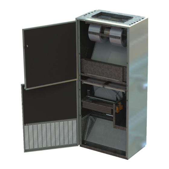
Freshman Series
1000A and 1600A Cabinet
Classroom Air Handler Non-Compressorized
and Split Vertical Air Conditioner
This manual contains instructions specific to the installation, operation and service of your unit. If installed with the GHM9 gas heat
module, please refer to the GHM9 supplementary installation and operations guide that was also supplied along with this document.
Keep the manual(s) in a safe place and at the ready for future reference.
Should you require further information contact the factory or your regional Changeair representative.
Freshman Series
Owners Manual -
Installation, Operation, and Service Instructions
Version 1.1 EN
EN
Page 1
Improper installation,
adjustment, alteration,
service or maintenance can
cause property damage,
personal injury or loss
of life, and could cause
exposure to substances
which have been
determined by various state
agencies to cause cancer,
birth defects or other
reproductive harm.
Read and understand the
installation, operating, and
maintenance instructions
thoroughly before installing
or servicing this equipment.
Installation and
maintenance must be
done by a qualified
installer, service agency, or
authorized dealer.
OPERATION OF UNIT
DURING CONSTRUCTION
MAY VOID THE
WARRANTY.
Advertisement
Table of Contents
Troubleshooting

Related Manuals for SystemAir changeair Freshman Series


Summary of Contents for SystemAir changeair Freshman Series
- Page 1 Freshman Series Owners Manual - Installation, Operation, and Service Instructions Version 1.1 EN Freshman Series 1000A and 1600A Cabinet Classroom Air Handler Non-Compressorized Improper installation, and Split Vertical Air Conditioner adjustment, alteration, service or maintenance can cause property damage, personal injury or loss of life, and could cause exposure to substances which have been...
- Page 2 Freshman Series - Owner's Manual - Installation, Operation, and Service Instruction - Version 1.1 EN...
-
Page 3: Table Of Contents
List of Sections List of Sections 1.0 Symbols and Warnings ............4 6.3 General Assembly and Installation ........20 6.4 Electrical Connections ............22 2.0 Identification ..............5 6.5 Wall Sleeve ................22 2.1 General Information ..............5 6.6 Figure 11 | General Wall Sleeve Assembly ......23 2.2 Unit Inspection ................5 6.7 Exterior Louver .............. -
Page 4: Symbols And Warnings
Symbols and Warnings 1.0 Symbols and Warnings This is a safety alert symbol. When you see this symbol on labels or in manuals, be alert to the potential for personal injury. Understand and pay particular attention to words DANGER, WARNING, and CAUTION. DANGER indicates an imminently hazardous situation, which, if not avoided, will result in death or serious injury. -
Page 5: Identification
Identification 2.0 Identification 2.1 General Information 2.2 Unit Inspection Please keep this page for future reference Inspected For Freight Damages You have just purchased a Freshman Series Air Handling Unit. Your air handling unit was carefully packed for shipping. This This design is certified by the Canadian Standards Association means that the packaged product, with normal handling, will (CSA) and bears the label indicating it has been tested to the... -
Page 6: Limited Warranty
Limited Warranty 3.0 Limited Warranty LIMITED WARRANTY LIMITED STANDARD PARTS ONLY WARRANTY (14 months) This Changeair product is warranted to the original purchaser to be free from defects in material and workmanship under normal use and maintenance, consistent with Changeair instructions or recommendations for use and maintenance, for a period of 14 months from shipping date. Changeair’s sole responsibility under this parts warranty will be to replace any part which fails to comply with this warranty during such warranty period, provided customer has promptly reported same to Changeair. - Page 7 Limited Warranty No claim or demand may be asserted against Changeair or its employees, agents, directors, officers, representatives and/or suppliers hereunder unless the injury, loss or damage giving rise to such claim or demand is sustained within the applicable warranty period referred to above and unless such claim or demand is first asserted within twelve months after the injury, loss or damage has occurred.
-
Page 8: Model Number Nomenclature
Model Number Nomenclature 4.0 Model Number Nomenclature 4.1 Table 1 | Freshman Series - Nomenclature Freshman Series - Owner's Manual - Installation, Operation, and Service Instruction - Version 1.1 EN... -
Page 9: General Preventative Maintenance
General Preventative Maintenance 5.0 General Preventative Maintenance 5.1 General Information NOTE: By performing proper preventative maintenance your unit will The following is a generalized list of operate economically and dependably. Instructions for basic maintenance procedures that pertains to maintenance are found below. all Changeair Air Handlers, therefore one or more of the procedures may not apply to Always turn OFF electrical power supply before cleaning... -
Page 10: Filter Maintenance
General Preventative Maintenance 5.3 Filter Maintenance Filtering Out Trouble Dirty air filters will cause air flow reduction through your unit. If excessive air loss occurs, the unit may freeze up when in the air conditioning mode, or cycle on high and limit safety controls during heating mode. -
Page 11: Removing Supply Fan(S)
General Preventative Maintenance 5.4 Removing Supply Fan(s) Remove SUPPLY FAN MOTOR as follows A qualified service technician Turn OFF electrical supply to the unit. should perform the following. Open front service panels of unit using key provided. Disconnect the wire harness running to the fan motor. (Fig. 2) Remove fastening screws from either side of fan assembly Pull fan assembly straight out of unit and clean dirt from fan blades and around motor housing. -
Page 12: Cleaning Supply And Relief Fans
General Preventative Maintenance 5.5 Cleaning Supply and Relief Fans Remove Fan from unit. (Refer to Section 5.5) Take a brush or similar cleaning tool and clean blades of fan to remove built up attached dirt. Use a vacuum or compressed air and clean entire fan including the blades. Replace fan in unit. -
Page 13: Coil Maintenance
General Preventative Maintenance 5.6 Coil Maintenance Heating Coil (Open Access) Using a coil brush remove/dislodge excess foreign matter. Coil fins are delicate and Vacuum loosened foreign matter. can be damaged easily. Using compressed air, clean coil in reverse direction of air flow and/or using an Clean with care. -
Page 14: Cleaning Energy Recovery Filters
General Preventative Maintenance 5.7 Cleaning Energy Recovery Filters Dirty air filters will cause air flow reduction through your unit. If excessive air loss occurs, the unit may freeze up when in the air conditioning mode, or cycle on high and limit safety controls during heating mode. If this condition persists the unit may be locked out by the safety circuits. -
Page 15: Removing Fixed Core Plates
General Preventative Maintenance 5.8 Removing Fixed Core Plates Turn OFF electrical power to the air handler. Open front service panels with the key provided. Slide return air filter up and out of brackets and set aside. Remove the screws holding the exchange core cover plate and remove plate. Loosen the screws on the exchange core cover plate. -
Page 16: Cleaning Fixed Core Plates
General Preventative Maintenance 5.9 Cleaning Fixed Core Plates If cores are wet allow them to dry before cleaning Using low psi compressed air blow dirt out of cores in the opposite direction of the air flow (Fig. 7) Once clean, repeat the core removal steps in reverse order to install the cores Once installed, close doors and turn electrical power back on. - Page 17 General Preventative Maintenance 5.10 Removing Relief Fan(s) Motor - continued Unplug the electrical wires running to the recovery fan motor. Remove the 4 bolts located on top of the return air damper pan that holds the recovery fan motor. Pull down on fan and remove from unit.
-
Page 18: Cleaning The Energy Recovery Wheel
General Preventative Maintenance 5.11 Cleaning The Energy Recovery Wheel Cleaning Instructions Turn OFF electrical supply to the unit. Open front service panels using key provided. Disconnect the wire harness to the actuator located on the return air damper. Remove the screws that is holding return air damper in place. Remove the relief air filter. -
Page 19: Installation Guide
Installation Guide 5.12 Figure 10 | Removing Relief Fan(s) Relief Fan(s) Return Air Damper 6.0 Installation Guide 6.2 Table 2 | Minimum Operational Clearances 6.1 General Pre-Installation A location should be selected that will give the best circula- Minimum Operational Clearances tion of the conditioned room air. -
Page 20: General Assembly And Installation
Installation Guide 6.3 General Assembly and Installation It is important to read and understand the instructions outlined in this document, as well as any job specific documentation pro- vided in the Information Package before proceeding with the installation. Care should be taken to protect the painted finish when handling the unit and accessories. Classroom Air Handlers weigh anywhere from 420lbs to 1070lbs and may be heavy. - Page 21 Installation Guide 6.3 General Assembly and Installation - continued Check to be sure that the back of the Classroom Air Handler is centered directly in front of the wall sleeve opening, and then carefully slide the air handler back into place (the unit must be level). If the wall is not perfectly perpendicular to the floor, it may be necessary to slide shims under the front or back of the air handler.
-
Page 22: Electrical Connections
Installation Guide 6.4 Electrical Connections Attention: Electrician It is recommended that each unit be installed on a permanent, separate electrical circuit. The circuit must be protected by a fuse or HACR type circuit breaker. Always turn off the electrical To minimize risk, the unit is equipped with a door switch to disable the 24 VAC supply to the unit before control voltage, de-energizing the internal contacts when the main access panels repair or major service. -
Page 23: Exterior Louver
Installation Guide 6.6 Figure 11 | General Wall Sleeve Assembly Wall Sleeve Assembly Exterior Louver A. Wall Sleeve with a divider for relief air B. Wall Sleeve for standard Wall Sleeve Assembly ventilation 6.7 Exterior Louver NOTE: The exterior louver is supplied with the unit and should slide into the wall sleeve Two condensate drain from the outside of the building. -
Page 24: Relief Damper
Installation Guide 6.8 Relief Damper Changeair recommends the use of a relief damper assembly be Cut or construct an opening through the wall adherent to used in conjunction with all units installations unless balanced the appropriate size. powered exhaust is made available within the ventilated On the exterior, run a bead of weatherproof caulking space. -
Page 25: Rear Standoff (Rso)
Installation Guide 6.10 Rear Standoff (RSO) We recommend the use of ¾” x #10 round head self-tapping NOTE: sheet metal screws to fasten the accessories to the unit. When the vertical classroom unit is fitted with a rear standoff (RSO) or rear plenum Care should be taken to protect the painted finish when assembly (RPA) it becomes necessary handling the unit and accessories. -
Page 26: Top Plenum
Installation Guide 6.11 Top Plenum 6.12 Rear Plenum Assembly (RPA) We recommend the use of ¾” x #10 round head self-tapping Carefully unpack the plenum assembly. The plenums sent sheet metal screws to fasten this accessory to the air handler. with the units may vary in height or model, and will be labeled with a UV# if provided. -
Page 27: Top Duct Cover
Installation Guide 6.13 Top Duct Cover 6.12 Rear Plenum Assembly (RPA) - continued Carefully unpack the top duct cover. Remove the front access covers from the appropriately Position the Classroom Air Handler directly in front of its selected top duct cover. final installation position. -
Page 28: Installation Drawings
Installation Drawings 7.0 Installation Drawings 7.1 Figure 13 | Freshman - CA H 1000A NA VP DD Freshman Series - Owner's Manual - Installation, Operation, and Service Instruction - Version 1.1 EN... - Page 29 Installation Drawings 7.2 Figure 14 | Freshman - CA H 1000A NA VPS DD Freshman Series - Owner's Manual - Installation, Operation, and Service Instruction - Version 1.1 EN...
- Page 30 Installation Drawings 7.3 Figure 15 | Freshman - CA H 1600A NA VP DD Freshman Series - Owner's Manual - Installation, Operation, and Service Instruction - Version 1.1 EN...
- Page 31 Installation Drawings 7.4 Figure 16 | Freshman - CA H 1600A NA VPS DD Freshman Series - Owner's Manual - Installation, Operation, and Service Instruction - Version 1.1 EN...
-
Page 32: Troubleshooting Guide
Troubleshooting Guide 8.0 Troubleshooting Guide Changeair is not responsible for injury to untrained or unauthorized personnel who attempt to do repairs based on the trouble shooting procedures outlined in this section. 8.1 General Information 8.3 Controls Your Changeair Classroom Air Handling Unit has been manu- Control of the unit is achieved through an external device, factured with great care and top rated quality control. -
Page 33: General Unit Sequence Of Operations
Troubleshooting Guide Changeair is not responsible for injury to untrained or unauthorized personnel who attempt to do repairs based on the trouble shooting procedures outlined in this section. opens at 150°F and resets automatically, and a line voltage fuse at the element which opens at 219°F and will not Heat automatically reset, consult a service technician to replace Hydronic/Steam... -
Page 34: General Air Handler Troubleshooting
Troubleshooting Guide Changeair is not responsible for injury to untrained or unauthorized personnel who attempt to do repairs based on the trouble shooting procedures outlined in this section. 8.6 General Air Handler Troubleshooting Problem - Unit Tripped Breakers Incorrect fuse; check fuse size. NOTE: Replacement Fuses must Short circuit or incorrect unit wiring line voltage;... -
Page 35: Cooling Troubleshooting
Troubleshooting Guide Changeair is not responsible for injury to untrained or unauthorized personnel who attempt to do repairs based on the trouble shooting procedures outlined in this section. 8.7 Cooling Troubleshooting Problem - Temperature drop between mixed air and supply is less than 18°F. If it is more than this, the unit is operating properly. -
Page 36: Replacement Parts
Replacement Parts 9.0 Replacement Parts 9.1 Obtaining Parts Contact your dealer or the factory for questions concerning prices and policies on replacement parts. When ordering replacement parts always give the following information: Replacement parts and service are available through • Model and Serial Number of Vertical Classroom Air your local Changeair representative. - Page 37 Notes Freshman Series - Owner's Manual - Installation, Operation, and Service Instruction - Version 1.1 EN...
- Page 38 10048 Industrial Blvd • Lenexa KS • USA 66215 8 Rouse Street • Tillsonburg ON • Canada N4G 5W8 50 Kanalflakt Way • Bouctouche NB • Canada E4S 3M5 Changeair reserves the right to update or continually improve their products, specifications or information without notice.
Need help?
Do you have a question about the changeair Freshman Series and is the answer not in the manual?
Questions and answers
motor speed adjustment,
To adjust the motor speed on a SystemAir Changeair, use the variable speed option provided. It is recommended not to use a constant speed setting. Variable speed allows adjustment based on required efficiency and pressure drop, improving energy use and system performance.
This answer is automatically generated