
Related Manuals for Ziton ZP2-F Series


Summary of Contents for Ziton ZP2-F Series
-
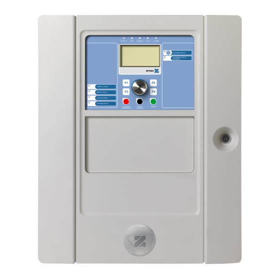
Page 1: Control Panel Operation
ZP2-F Series Fire Alarm Control Panel Operation Manual P/N 501-405203-2-20 • REV 2.0 • ISS 03MAR11... - Page 2 Copyright © 2011 UTC Fire & Security. All rights reserved. Trademarks and The ZP2-F Series name and logo are trademarks of patents UTC Fire & Security. Other trade names used in this document may be trademarks or registered trademarks of the manufacturers or vendors of the respective products.
-
Page 3: Table Of Contents
Summary of status indications 10 Control panel operation 14 User levels 14 Operation controls and procedures 15 Public level operation 16 Operator level operation 18 Maintenance 22 Menu maps 24 Regulatory information 25 ZP2-F Series Fire Alarm Control Panel Operation Manual... - Page 4 ZP2-F Series Fire Alarm Control Panel Operation Manual...
-
Page 5: Introduction
Introduction This is the operation manual for the ZP2-F Series Fire Alarm Control Panels. Read these instructions and all related documentation entirely before operating this product. Firmware compatibility Information in this document covers control panels with firmware version 2.0 or later. -
Page 6: Repeater Functionality
Fire routing and fire protection control and indication In this document, information on control and indication for fire routing and fire protection applies only to control panels that include those features. ZP2-F Series Fire Alarm Control Panel Operation Manual... -
Page 7: Control Panel Overview
22. Fire Routing On/Acknowledged button and 11. Panel Silence button and LED 12. Sounder Start/Stop Button and LED For a detailed overview of front panel controls and indicators, see “Front panel controls and indicators” on page 4. ZP2-F Series Fire Alarm Control Panel Operation Manual... -
Page 8: Front Panel Controls And Indicators
LED A flashing LED indicates that fire protection has been activated. A steady LED indicates that the fire protection signal has been acknowledged by the remote monitoring equipment. ZP2-F Series Fire Alarm Control Panel Operation Manual... - Page 9 Flashing indicates that a delay is counting (sounders are activated when the configured delay elapses or when the delay is cancelled) • Off indicates that the sounders are off (or will be deactivated shortly) ZP2-F Series Fire Alarm Control Panel Operation Manual...
- Page 10 The fire routing indication displays the acknowledged status but not the activation status (the acknowledgement status takes priority). For more information on your control panel configuration and indications, contact your installation or maintenance contractor. ZP2-F Series Fire Alarm Control Panel Operation Manual...
-
Page 11: Lcd Controls And Indicators
6. Soft keys (menu options linked to function buttons F1, F2, F3, and F4) 7. Jog dial 8. Function buttons F1, F2, F3, and F4 9. Local control panel ID (in a fire network) ZP2-F Series Fire Alarm Control Panel Operation Manual... - Page 12 This icon indicates that the system has detected a Manual call point alarm [1] manual call point alarm. [1] These icons appear in the message display area with the notification details. ZP2-F Series Fire Alarm Control Panel Operation Manual...
-
Page 13: Indication Of Remote And Local Events On The Lcd
Input activation An input is activated (subject to configuration) Output group activation An output group is activated New node in the fire network A control panel has been added to the fire network ZP2-F Series Fire Alarm Control Panel Operation Manual... -
Page 14: Summary Of Status Indications
• If a fire routing delay has been enabled the Fire Routing Delay LED is steady • If a fire protection delay has been enabled the Fire Protection Delay LED is steady ZP2-F Series Fire Alarm Control Panel Operation Manual... - Page 15 If configured to do so by your installation or maintenance contractor, a steady Fire Routing ON/Acknowledged LED indicates that the fire routing signal has been acknowledged by the remote monitoring equipment. ZP2-F Series Fire Alarm Control Panel Operation Manual...
- Page 16 (if the corresponding zone is included on the zone board) • The control panel buzzer sounds intermittently (short tone) For more information on the disablement, press F1 (Show Events) and then select Conditions. ZP2-F Series Fire Alarm Control Panel Operation Manual...
- Page 17 Customers who wish to obtain maximum standby time from batteries (24 to 72 hours) may see this fault indication. A low battery indication means that the batteries are discharged and does not indicate that they are defective. ZP2-F Series Fire Alarm Control Panel Operation Manual...
-
Page 18: Control Panel Operation
Your maintenance or installation contractor may have configured the control panel to remember the last login details entered. To exit a restricted user level: 1. Press F3 (Logout) from the Main menu. ZP2-F Series Fire Alarm Control Panel Operation Manual... -
Page 19: Operation Controls And Procedures
Select this option to exit the configuration process without storing or applying the current configuration change. Note: When updating multiple configuration settings, we recommend that you save after each change and then apply all changes from the Main menu. ZP2-F Series Fire Alarm Control Panel Operation Manual... -
Page 20: Public Level Operation
A flashing Fire Protection Delay LED during a fire alarm indicates that the configured delay is active (fire protection is activated when the configured delay elapses or when the delay is cancelled). ZP2-F Series Fire Alarm Control Panel Operation Manual... - Page 21 Note: This information is only available if your installation or maintenance contractor has included it in the fire system configuration. ZP2-F Series Fire Alarm Control Panel Operation Manual...
-
Page 22: Operator Level Operation
To manually start the sounders when the control panel is not in alarm, press the Sounder Start/Stop button. Note: Availability of this feature is subject to previous configuration. Contact your installation or maintenance contractor to confirm your configuration details. ZP2-F Series Fire Alarm Control Panel Operation Manual... - Page 23 Note: Availability of this feature is subject to previous configuration and its functionality may vary for each zone. Contact your installation or maintenance contractor to confirm all configuration details for your site. ZP2-F Series Fire Alarm Control Panel Operation Manual...
- Page 24 3. Enter and then confirm your new password. 4. Press F4 (Enter), and then press F1 (Back). 5. Press F1 (Save), F3 (Apply), F4 (Discard), or F2 (Exit). Remember to apply saved settings from the Main menu. ZP2-F Series Fire Alarm Control Panel Operation Manual...
- Page 25 1. Select Tests from the Main menu. 2. Select UI tests, and then LCD test. A test pattern displays on the LCD to help identify the location of defective pixels. 3. Press F2 (Exit). ZP2-F Series Fire Alarm Control Panel Operation Manual...
- Page 26 View the alarm counter Select the Alarm counter option to view the total number of fire alarms recorded by the control panel. The alarm counter value cannot be reset. ZP2-F Series Fire Alarm Control Panel Operation Manual...
-
Page 27: Maintenance
Keep the outside and inside of the control panel clean. Carry out periodic cleaning using a damp cloth for the outside. Do not use products containing solvents to clean the unit. Do not clean the inside of the cabinet with liquid products. ZP2-F Series Fire Alarm Control Panel Operation Manual... -
Page 28: Menu Maps
Indicator test Keyboard test LCD test Reports Event log View all Attention required Revision Firmware revision Configuration revision Serial numbers Contact details Panel I/O status Firenet status Alarm counter Password setup Change password ZP2-F Series Fire Alarm Control Panel Operation Manual... -
Page 29: Regulatory Information
EN 54-4: 1997 + A1: 2002 + A2: 2006 Year of manufacture The year and day of manufacture, in the format YYDDD, is included in the first five digits of your product serial number (located on the product identification label) ZP2-F Series Fire Alarm Control Panel Operation Manual... - Page 30 These control panels have been designed in accordance with the following European standards for electrical safety and electromagnetic compatibility: • EN 60950-1 • EN 50130-4 • EN 61000-6-3 • EN 61000-3-2 • EN 61000-3-3 ZP2-F Series Fire Alarm Control Panel Operation Manual...
- Page 31 ZP2-F Series Fire Alarm Control Panel Operation Manual...
Need help?
Do you have a question about the ZP2-F Series and is the answer not in the manual?
Questions and answers