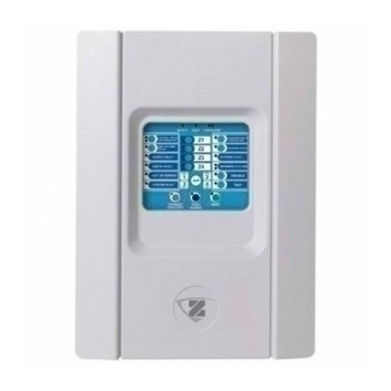
Ziton zp1-f Series Operation Manual
Fire alarm control panels
Hide thumbs
Also See for zp1-f Series:
- Quick operation manual (2 pages) ,
- Quick installation manual (4 pages) ,
- Installation manual (113 pages)
Table of Contents
Advertisement
Advertisement
Table of Contents

Related Manuals for Ziton zp1-f Series


Summary of Contents for Ziton zp1-f Series
- Page 1 ZP1-F Series Operation Manual P/N 501-415603-2-31 • REV 03.10 • ISS 13NOV13...
- Page 2 Ul. Kolejowa 24. 39-100 Ropczyce, Poland. Authorized EU manufacturing representative: UTC Fire & Security B.V. Kelvinstraat 7, 6003 DH Weert, Netherlands. Version This document applies to ZP1-F Series control panels with software version 2.0 or later. Certification European Union 2004/108/EC (EMC directive).
-
Page 3: Table Of Contents
User interface for eight-zone control panels 4 Operator controls and indicators 5 Audible indicators 9 Summary of status indications 9 Control panel operation 13 User levels 13 Public user level operation 13 Operator user level operation 16 Maintenance 22 Regulatory information 23 ZP1-F Series Operation Manual... -
Page 4: Important Information
Installation in accordance with this manual, applicable codes, and the instructions of the authority having jurisdiction is mandatory. While every precaution has been taken during the preparation of this manual to ensure the accuracy of its contents, UTCFS assumes no responsibility for errors or omissions. ZP1-F Series Operation Manual... -
Page 5: Introduction
Introduction This is the operation manual for the ZP1-F Series fire alarm control panels. Read these instructions and all related documentation entirely before operating this product. Product range The ZP1-F Series includes the models shown below. Table 1: ZP1-F Series models... -
Page 6: Sounder And Fire Routing Delays
Fire routing delay Extended fire routing delay EN 54-2 EN 54-2 Evacuation EN 54-2 Scandinavia BS 5839-1 NBN S 21-100 (evacuation sounders) (warning sounders) NEN 2535 Note: Fire routing is not available on any two-zone control panel. ZP1-F Series Operation Manual... -
Page 7: Control Panel Overview
11. General Test button and LED Notes [1] Two-zone control panels do not include fire routing or warning sounders for NEN2535. [2] Regional variants include changes to interface buttons and LEDs as shown in Table 4 on page 4. ZP1-F Series Operation Manual... -
Page 8: User Interface For Eight-Zone Control Panels
Sounder Delay Fire Protection Fault/Disable/Test Evacuation Sounder Delay Reserved Fault Warning Fault/Disabled Reserved Sounder Start/Stop Sounder Start/Stop Evacuation Start/Stop Fire Routing Delay Fire Routing Delay Warning Sounder Delay Fire Routing ON/ACK Fire Routing ON/ACK Warning Sounders Start/Stop ZP1-F Series Operation Manual... -
Page 9: Operator Controls And Indicators
A flashing LED indicates a fault with the sounders — or — or evacuation sounders. A steady LED indicates Evacuation that the sounders or evacuation sounders are Fault/Disable/Test disabled or are being tested. button and LED for NBN S 21-100) ZP1-F Series Operation Manual... - Page 10 LED protection and fault warning (NEN 2535 only), or expansion I/O boards (when pressed with the corresponding button). A steady General Disable LED and the corresponding zone, sounders, or fire routing Fault/Disable/Test LED indicates a disablement. ZP1-F Series Operation Manual...
- Page 11 Depending on the size of your installation, the processing of commands to start or stop sounders may take a few seconds to travel through the system. For example, the LED may be steady before the sounders are audible. ZP1-F Series Operation Manual...
- Page 12 LED A flashing LED indicates a fault. A steady LED — or — indicates that the function is disabled or is being tested. Warning Fault/Disable/Test button and LED for NBN S 21-100 ZP1-F Series Operation Manual...
-
Page 13: Audible Indicators
(counting). Flashing fast when an extended fire routing delay is active (counting). • Fire Routing ON/ACKd LED: Flashing when fire routing is activated. On steady when the fire routing signal has been acknowledged by the remote monitoring equipment. • Control panel buzzer: Sounding continuous. ZP1-F Series Operation Manual... - Page 14 Mains power fault and mains fuse fault indication: • General Fault LED: Flashing. • Supply Fault LED: On steady. • Control panel buzzer: Sounding intermittent. Battery power and battery fuse fault indication: • General Fault LED: Flashing. ZP1-F Series Operation Manual...
- Page 15 Fire Protection LED: On steady yellow. • Control panel buzzer: Off. Disabled fault warning is indicated as follows: • General Disable LED: On steady. • Fault Warning LED: On steady yellow. • Control panel buzzer: Off. ZP1-F Series Operation Manual...
- Page 16 When power is re-established the control panel returns to its former status. Note: When the control panel indicates out of service, your fire alarm system is partly inactive and your site is not properly protected. Contact your installation or maintenance contractor immediately to investigate the problem. ZP1-F Series Operation Manual...
-
Page 17: Control Panel Operation
Cancel an active sounder (or evacuation for NBN S 21-100) delay • Cancel an active fire routing (or warning for NBN S 21-100) delay • Perform a control panel LED and buzzer test • Display local indications only (for control panels with repeater functionality) ZP1-F Series Operation Manual... - Page 18 (or warning for NBN S 21-100) immediately. Performing a control panel LED indicator and control panel buzzer test To perform a control panel LED indicator and buzzer test, press and hold the Test button for more than 3 seconds. ZP1-F Series Operation Manual...
- Page 19 Pushing Enter for 3 seconds in panel 1 will cause the red LED indication of zone 8 to disappear, indicating that the control panel has zone 8 disabled. At this point, ZP1-F Series Operation Manual...
-
Page 20: Operator User Level Operation
To stop the sounders (or evacuation for NBN S 21-100), press the Sounder Start/Stop button (or Evacuation Start/Stop button for NBN S 21-100). To restart stopped sounders (or evacuation for NBN S 21-100), press the button again. ZP1-F Series Operation Manual... - Page 21 NBN S 21-100). To disable the delay, press the button again. Note: Availability of this feature is subject to configuration and its functionality may vary for each zone. Contact your fire system installation or maintenance contractor to confirm your configuration details. ZP1-F Series Operation Manual...
- Page 22 To end the test, press the Test button, and then press the Zone button again. If there is a fire alarm in another zone not in test, the control panel responds to the alarm event as configured. ZP1-F Series Operation Manual...
- Page 23 To disable sounders (or evacuation for NBN S 21-100), press the General Disable button, and then press the Sounder Fault/Disable/Test button (or Evacuation Fault/Disable/Test button for NBN S 21-100). Sounders (or evacuation for NBN S 21-100) can only be disabled when the control panel is in standby. ZP1-F Series Operation Manual...
- Page 24 Fire Routing ON/ACK button (or Warning Start/Stop button for NBN S 21-100) again. Note: Disabled fire routing (or warning for NBN S 21-100) does not operate or indicate a fault if there is a fire alarm. Disabling or enabling other features ZP1-F Series Operation Manual...
- Page 25 To enable a disabled option, press the General Disable button for more than 3 seconds, press the 1 and 3 buttons to select the option to be enabled, and then press Enter. Note: Disabled expansion boards will not operate or indicate a fault if there is a fire alarm. ZP1-F Series Operation Manual...
-
Page 26: Maintenance
Keep the outside and inside of the control panel clean. Carry out periodic cleaning using a damp cloth for the outside. Do not use products containing solvents to clean the unit. Do not clean the inside of the cabinet with liquid products. ZP1-F Series Operation Manual... -
Page 27: Regulatory Information
European standards for electrical safety and electromagnetic compatibility These control panels have been designed in accordance with the following European standards for electrical safety and electromagnetic compatibility: • EN 60950-1 • EN 50130-4 • EN 61000-6-3 • EN 61000-3-2 • EN 61000-3-3 ZP1-F Series Operation Manual... - Page 28 Declaration of Performance number ZP1-F2, ZP1-F2-SC 360-3100-1199 ZP1-F4, ZP1-F4-NL, ZP1-F4-SC 360-3100-1299 ZP1-F8, ZP1-F8-NL, ZP1-F8-SC 360-3100-1399 Product identification See model number on product identification label Intended use See DoP point 3 Essential characteristics See DoP point 9 ZP1-F Series Operation Manual...
Need help?
Do you have a question about the zp1-f Series and is the answer not in the manual?
Questions and answers
what is the factory reset password of the ZP1-F8 series panel
The factory reset password for the Ziton ZP1-F Series panel is 3333.
This answer is automatically generated
Disable or enable a zone
To disable or enable a zone on the Ziton ZP1-F Series control panel:
1. Access the zone configuration menu.
2. Select the desired zone (e.g., Zone 1) and press Enter.
3. The Zone fault/test/disable LED will flash fast, indicating the menu is active.
4. Use the value selection buttons (2 and 4) to choose the desired setting.
5. Press Enter to confirm.
6. Save your changes.
Disabling/enabling a zone affects only the local control panel unless it is repeated on another panel.
This answer is automatically generated