Ziton ZP3 Installation And Maintenance Manual
Fire control panel
Hide thumbs
Also See for ZP3:
- Installation operation & maintenance (239 pages) ,
- Installation manual (34 pages)

Related Manuals for Ziton ZP3


Summary of Contents for Ziton ZP3
- Page 1 ZP3 Fire Control Panel Installation, Commissioning, and Maintenance Manual P/N 503-1160ZE-I-12 • REV 12.0 • ISS 13SEP11...
- Page 2 © 2011 UTC Fire & Security. All rights reserved. The ZP3 name and logo are trademarks of UTC Fire & Security. Other trade names used in this document may be trademarks or registered trademarks of the manufacturers or vendors of the respective products.
-
Page 3: Table Of Contents
EN 54 Setup requirements 101 Introduction 106 Verification 106 System tests 108 Introduction 112 Peer-to-peer 3 (P2P3) protocol 112 Panel filters set, store and send capability 114 New network filters 114 Language loading 116 ZP3 Fire Control Panel Installation, Commissioning, and Maintenance Manual... - Page 4 Introduction 118 System cabling 120 Z-Address lines 121 Serial communication lines 128 DC control lines 130 Overview 132 Routine maintenance 132 Maintenance menu 135 Interpretation of analogue readings 143 Corrective maintenance 150 ZP3 Fire Control Panel Installation, Commissioning, and Maintenance Manual...
- Page 5 Trained service personnel must carry out procedures in this manual. The ZP3 panel is powered from a 230 VAC primary supply and from a 24 VDC battery backup supply. The power supply forms part of the main board assembly. This assembly consists of a circuit board (incorporating the power supply), mounted on a metal chassis, with the power supply covered by a metal enclosure.
- Page 6 The backup batteries contain substances that are potentially hazardous to your health and to the environment. ZP3 Fire Control Panel Installation, Commissioning, and Maintenance Manual...
- Page 7 8.9 Output to fault warning routing equipment (output to J) 9.5 Disablement of addressable points Test conditions 10.1 General requirements 10.2 Indication of the test condition 10.3 Indication of zones in the test state Standardized input/output interface ZP3 Fire Control Panel Installation, Commissioning, and Maintenance Manual...
- Page 8 ZP3AB-NET1 Network Board Installation Sheet 501-0485ZE-1-01 ZP3AB-SCB-D Serial Display Unit Interface Installation Sheet 501-0482ZE-1-01 Planner User Guide 503-1436ZE-U-06 European Standard EN 54 (Parts 2 and 4) British Standards BS 5839 (Part 1: 1988) ZP3 Fire Control Panel Installation, Commissioning, and Maintenance Manual...
-
Page 9: Introduction
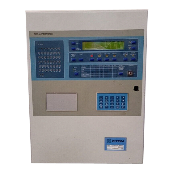
Display and controls 10 Panel construction 10 Built-in communication port 16 Optional modules 19 Communication boards 19 Remote display unit 25 Accessory plate 25 Modem 28 Printer 31 Quick start 34 ZP3 Fire Control Panel Installation, Commissioning, and Maintenance Manual... - Page 10 Chapter 1: Installation overview The ZP3 fire control panel (see Figure 1) is a state-of-the-art analogue addressable panel that complies with EN 54 parts 2 and 4. It is a compact microprocessor controlled unit, of modular design. Hardware and software modules enable you to configure virtually any system requirement.
-
Page 11: Specifications
Chapter 1: Installation overview Refer to Table 4 below for detailed specifications for the ZP3 Fire Control Panel. Fire alarm panel Complies with European Standard EN 54-2 Power supply Complies with European Standard EN 54-4 Electromagnetic CE Marked. Complies with European Directive 89/336/EEC. - Page 12 Panel (alarm at 24 VDC) 500 mA Load of panel only, excluding any external devices Per Loop (quiescent at 24 150 mA Fully loaded loop, with 127 ZP VDC) devices, not in alarm ZP3 Fire Control Panel Installation, Commissioning, and Maintenance Manual...
- Page 13 For connection to fault alarm RMC routing equipment Zone walk test EN 54-2 One-man test of a zone, other zones remain working Control outputs EN 54-2 Up to 768 programmable control outputs ZP3 Fire Control Panel Installation, Commissioning, and Maintenance Manual...
- Page 14 Scroll events (more) Button Manually scrolls the list of alarms on LCD screen Controls ON/OFF Key switch Enables or disables front panel controls Operator menu/keypad Keypad For operator, maintenance, and setup menus ZP3 Fire Control Panel Installation, Commissioning, and Maintenance Manual...
- Page 15 Voltage-free relay contacts, common to fault alarms Remote manned centre (fire) Monitored voltage output to RMC transmitter for fire Remote manned centre (fault) Monitored voltage output to RMC transmitter for fault ZP3 Fire Control Panel Installation, Commissioning, and Maintenance Manual...
- Page 16 [5] In a fire alarm condition, the battery charging is disconnected. Therefore, in a fire condition, additional current is available for external fire alarm devices only, such as sounders. ZP3 Fire Control Panel Installation, Commissioning, and Maintenance Manual...
- Page 17 Chapter 1: Installation overview See Figure 2 for the dimensions of the ZP3 fire alarm panel. The basic panel is designed for surface mounting, and flush-mounting kits are available. The dimensions below apply to the basic panel. For details of optional mounting hardware, see the appropriate data sheets.
- Page 18 The printer is an optional item. The ZP3 fire control panel (see Figure 4) is of modular design so that it can be configured for any required application. It consists of a basic panel, which is fully functional, and available in three models, one-loop, two-loop, and four-loop.
- Page 19 Chapter 1: Installation overview Figure 4 shows the basic fire panel. The elements shown provide all required functions, and form the core of the ZP3 panel. No optional I/O modules or printer are shown in this illustration. Three communication boards are fitted.
- Page 20 Optional hardware is available for different installation requirements. Figure 6 shows all the main features of the ZP3 panel main chassis assembly. This unit comprises the line drivers, the I/O circuitry, the control circuits, the power supply, and the plug-in central processing unit (CPU).
- Page 21 36. LED 21 ADC failure 18. Battery/external 24V 37. To auxiliary boards 19. Monitored sounder 1 38. To display PCB The main chassis is removed from the panel by removing the four securing screws. ZP3 Fire Control Panel Installation, Commissioning, and Maintenance Manual...
- Page 22 There are no field-serviceable parts in the assembly. Figure 7 shows all the main features of the ZP3 panel Door Assembly. This unit comprises the panel display and control electronics as well as the keyboard, a serial connection for data loading, and the printer (if fitted).
- Page 23 Chapter 1: Installation overview ZP3 Fire Control Panel Installation, Commissioning, and Maintenance Manual...
- Page 24 13. Commissioning board 7. Earth path to chassis The built-in RS-232 port is used to connect the ZP3 panel to an external computer for the purpose of uploading or downloading the panel’s configuration ZP3 Fire Control Panel Installation, Commissioning, and Maintenance Manual...
- Page 25 (the programme) and then loaded into the panel at the site via a portable PC. This port can also be used to upgrade the ZP3 panel software to a new version. The preferred baud rate settings when using Planner to configure a ZP3 panel are shown in Table 5 below.
- Page 26 Chapter 1: Installation overview RS-232 is officially specified as having a maximum cable length of 10 metres, which is more than adequate for ZP3/PC configuration functions. The connecting cable must be screened, and must be made-up as per Figure 10. Alternatively, a standard null modem cable can be used.
- Page 27 Chapter 1: Installation overview The standard ZP3 fire panel has one built-in communication port, Z-Port 1, used for programming. Additional ports are available as options for other functions, such as connecting into a Ziton ZP-NET network, connecting to graphics display computers, as well as to remote display units and remote control units.
- Page 28 The ZP3AB-RS232 Serial Communications Board (see Figure 13) is used to connect a ZP3 panel to an external device, such as a desktop printer, a graphics display system, a building management system, modem, or a paging system.
- Page 29 Although the ZP3AB-NET1 board is capable of dual routing operation, ZP3 software does not support this feature, and the board must be used as a single-channel device. In a network of ZP3 panels, one of the ZP3 Fire Control Panel Installation, Commissioning, and Maintenance Manual...
- Page 30 To be functional, the optional ZP3AB-NET1 Network Board (Z-Port 2) must be configured in software. Access the communications parameters menu using the following menu path: Setup > System Configuration > Peripheral Comms > Comms Parameters The following screen is displayed. ZP3 Fire Control Panel Installation, Commissioning, and Maintenance Manual...
- Page 31 Stop bits = 1 The ZP3AB-SCB-D Serial Control Bus Driver Board is used to connect a number of remote display units (RDUs) and remote control units (RCUs) to a ZP3 fire panel. The hardware protocol is a multidrop RS-485 screened, two-wire connection.
- Page 32 The cable is specified in detail inAppendix A “ZP wiring guide” on page 117, but as a guideline it should be data quality cable with a conductor size of 0.5 mm². ZP3 Fire Control Panel Installation, Commissioning, and Maintenance Manual...
- Page 33 Chapter 1: Installation overview The ZP3 panel can operate 63 remote display units. The address range for the RDU is 1 to 63, which allows for up to 63 address options. The RDU is wired to the panel via the ZP3AB-SCB1 SCB driver board.
-
Page 34: Optional Modules
A ribbon cable is fitted to the accessory plate. Connecting the ribbon cable to the socket as shown in Figure 18 automatically connects all auxiliary boards to the ZP3 main board. The accessory plate enables easy access to the main board after installation. - Page 35 2. Position B 3. Position C The maximum number of auxiliary boards that can be fitted into a ZP3 panel is three. This can be all of one type, or a mix of types. This provides from 24 to 72 outputs within the ZP3 cabinet.
- Page 36 The Digi One 1A Modem as shown in Figure 20 allows remote dial-in access to the ZP3 panel for diagnostic purposes. The Modem communicates to the ZP3 panel via the serial port connector JP3 on the ZPAB-RS232 board located on the ZP3 panel. Legacy modems were additionally controlled via a Modem Control Board connected on the panel’s SSB...
- Page 37 3. Push the lower corner of the Modem in the direction of the arrow so it locks into position on the mounting bracket. 4. See Figure 23 on page 31. Fit the accessory plate (if necessary) to the ZP3 panel.
- Page 38 Chapter 1: Installation overview 1. Accessory plate 4. Bracket channel 2. Standoffs 5. M4 screws (4X) 3. Modem mounting bracket 6. Washers (4X) Mounting Modem slot Upper Mounting bracket Lower Catch ZP3 Fire Control Panel Installation, Commissioning, and Maintenance Manual...
- Page 39 ZPAB-RS232 board Modem An optional ZP3-PR2 dot-matrix printer kit can be fitted to the door of a ZP3 control panel. The printer kit consists of an ABLE printer, a Ziton Printer PCB and the necessary mounting hardware to fit to the ZP3 panel.
- Page 40 Weight 404 g including full-length paper roll EN 60529 Rating IP00 Figure 25 on page 33 illustrates the key installation elements for the printer. Detailed steps for installation follow the figure. ZP3 Fire Control Panel Installation, Commissioning, and Maintenance Manual...
- Page 41 Display board 1. Ensure that the ZP3 panel is powered down. 2. Remove the plastic knockout on the panel door. 3. Ensure that the orange and black cable is disconnected from the printer and separate the printer from its bracket by removing the mounting screws.
- Page 42 9. Connect the display board and the printer board to the printer using the ribbon cable provided, as shown in Figure 25 on page 33. 10. Connect 24 VDC power to the printer using the black and red ZP3 power lead.
-
Page 43: Unpacking Or Packing
Storing the main chassis 38 Overview of installation 39 Preparatory work 41 Installation information 42 Cable entry 42 Wiring 43 Surface mounting 44 Flush mounting 45 Backup batteries 46 Good practices 47 ZP3 Fire Control Panel Installation, Commissioning, and Maintenance Manual... - Page 44 Chapter 2: Installing the ZP3 fire control panel The ZP3 panel is shipped with the panel fully assembled. As only the panel backbox is normally mounted during the installation, the design anticipates that you will remove the door assembly and main chassis before the cabinet is sent to the site for electrical installation.
- Page 45 7. Remove the four nuts (item 6) and remove the chassis. 1. Earth strap 4. Securing screw 2. Wire * quick release connector 5. Power supply plug 3. SSB ribbon cable 6. Securing nut ZP3 Fire Control Panel Installation, Commissioning, and Maintenance Manual...
- Page 46 Repackage the chassis by wrapping it in a protective wrap (such as bubble wrap), and then placing it in the main panel carton. Chassis Carton ZP3 Fire Control Panel Installation, Commissioning, and Maintenance Manual...
-
Page 47: Preparatory Work
The first step when installing a ZP3 panel is to remove the main chassis, and remove the door assembly, leaving the bare backbox for installation. This procedure is described under “Preparatory work”... - Page 48 Chapter 2: Installing the ZP3 fire control panel The ZP3 fire panel is designed for mounting in an indoor location with a temperature range of 5°C to +40°C, a relative humidity of 95% noncondensing, and an environment that is dry and free of condensation. The environmental rating is IP30.
- Page 49 Chapter 2: Installing the ZP3 fire control panel Figure 30 shows the basic steps to mounting a ZP3 fire panel on the wall. Remove chassis and door assembly Bare backbox Knockout or drill holes Mount panel and connect conduits or cable glands...
- Page 50 Chapter 2: Installing the ZP3 fire control panel Cable entry and wiring locations for the ZP3 panel are restricted to specific areas as shown in Figure 31. 1. Knockout conduits 3. Low voltage cable area 2. Mains cable area 4. Electronics chassis It is very important to follow the above rules carefully.
- Page 51 1. Data cabling separated from other cables 4. Earth 2. Z-loops & low voltage control cabling 5. Serial Control Board (SCB) separated from high voltage cables 3. Mains cabling separate from low voltage wiring ZP3 Fire Control Panel Installation, Commissioning, and Maintenance Manual...
- Page 52 Use M4 screws at least 20 mm long. The mounting system must be able to support a minimum weight of 20 kg, which is the total weight of the panel (with batteries). ZP3 Fire Control Panel Installation, Commissioning, and Maintenance Manual...
- Page 53 Chapter 2: Installing the ZP3 fire control panel The ZP3 panel protrudes by only 10 mm when flush mounted. Two types of flush mounting kits are available, as shown and described in Figure 34 below. Both use the same collar, and look the same when installed. Flush mounting options are shown in Table 11 below.
- Page 54 (see Figure 36 on page 47). 7. Connect the backup batteries as described under “Battery connection” on page 54. Hook locator Hook mounting plate Securing hook Battery Battery mounting mounting position (left) position (right) ZP3 Fire Control Panel Installation, Commissioning, and Maintenance Manual...
- Page 55 Applying good practices during your installation ensures that the ZP3 system operates reliably and is trouble-free. These are simple actions that assist with commissioning and also provide stable long-term operation. The panel must be connected to a secure earth point. Door earth straps and internal earth must be connected.
- Page 56 Before fitting electronic assemblies, make sure that the cabinet is clean and free from metal filings, oil, or moisture, all of which can damage electronic circuits. Installing the wiring neatly and professionally to make commissioning and maintenance simpler and quicker. ZP3 Fire Control Panel Installation, Commissioning, and Maintenance Manual...
-
Page 57: Terminal Layout
Common fire / fault outputs 61 Remote manned centre outputs 62 Auxiliary boards 63 ZP3AB-RL8 Relay Board 63 ZP3AB-MA8 Monitored Output Board 64 ZP3AB-OP24 Transistor Output Board 65 ZP3AB-MIP8 Input Board 66 ZP3 Fire Control Panel Installation, Commissioning, and Maintenance Manual... - Page 58 Refer to Figure 38 on page 51. A terminal block (item 2) is located at the top right hand side of the fire panel for connecting the mains supply. The terminal block incorporates a fuse holder (item 1) in the live leg of the supply. A mains filter ZP3 Fire Control Panel Installation, Commissioning, and Maintenance Manual...
- Page 59 It can also be used to provide power to devices such as remote display units, and similar peripheral devices. ZP3 Fire Control Panel Installation, Commissioning, and Maintenance Manual...
- Page 60 Where the load required for optional accessory boards exceeds the capacity of the ZP3 power supply, it is possible to power these boards from a separate external 24 VDC power supply as shown in Figure 40. This external supply must meet the following criteria: •...
- Page 61 When using an external power supply unit, the failure of the mains supply, or the failure of the batteries, charging system, or fuse, can be reported to the ZP3 fire panel as shown below. The power supply unit must incorporate two sets of voltage-free contacts, one which changes over on mains failure, the other which changes over on battery fault (disconnected battery, low or high voltage, etc.),...
- Page 62 This section describes how to connect the batteries to the power supply (see Figure 42). Make sure that you comply with the “General warnings and precautions” on page iii and the recommendations provided under “Good practices” on page 47. ZP3 Fire Control Panel Installation, Commissioning, and Maintenance Manual...
-
Page 63: Battery Connection
The batteries must be connected in series with a jumper as shown in Figure 42. • Take care not to invert the battery connection polarity. If this happens, replace fuse F1 (6.3 A, slow-blow, 250 V, size 20 mm × 5 mm). ZP3 Fire Control Panel Installation, Commissioning, and Maintenance Manual... - Page 64 Chapter 3: Field wiring Two power supply calculations must be done when designing a ZP3 system: 1. The capacity must be calculated when running on mains power to ensure that it will be able to supply the system load, even when the batteries are disconnected or discharged.
- Page 65 Check Pass if the calculated load is below the PSU capacity, otherwise check Fail. Should the ZP3 PSU not be able to supply the system load, then either the system design must be modified, or a separate, external power supply must be used for part of the load.
-
Page 66: Z-Loop
(+) in to (+) out and ( ) in to ( ) out. The loop is monitored for open and short circuit. Unused loops must be terminated (+) in to (+) out and ( ) in to ( ) out. ZP3 Fire Control Panel Installation, Commissioning, and Maintenance Manual... - Page 67 The adjacent illustration shows two screen connections. Option B (the preferred method), has a shorter screen connection even though this results in longer plus and minus terminal wires. SCREEN SCREEN Option A Option B ZP3 Fire Control Panel Installation, Commissioning, and Maintenance Manual...
- Page 68 See Appendix A “ZP wiring guide” on page 117 for more details. See Figure 44 on page 61. The ZP3 Fire Control Panel has four built-in sounder outputs, arranged in two pairs. These outputs provide 24 VDC for driving sounders.
- Page 69 Setup menu. The common fire relay changes state on any fire alarm, and the common fault relay changes state on any fault alarm. Relays restore when the panel is reset. ZP3 Fire Control Panel Installation, Commissioning, and Maintenance Manual...
- Page 70 The remote manned centre (RMC) fault output sends a fault alarm signal to RMC-routing equipment upon occurrence of any panel or system fault. This transmits a fault signal to a remote manned centre such as a fire brigade, or a manned control room. ZP3 Fire Control Panel Installation, Commissioning, and Maintenance Manual...
- Page 71 See Figure 47 on page 64. The ZP3AB-RL8 Relay Board is a programmable relay board with eight separate relays. Each relay has a single changeover contact which changes state when activated. Relays are each allocated an ZP3 Fire Control Panel Installation, Commissioning, and Maintenance Manual...
- Page 72 I/O-mapping function built into the panel. The ZP3AB-RL8 board connects to the ZP3 panel control bus. If allocated to the User Bus section, up to 768 addresses are available. These outputs are freely programmable.
- Page 73 The load is provided from the 24 VDC supply connected to the power input terminals. If connected to the ZP3 panel auxiliary power supply terminals, the load is supplied from the built-in ZP3 power supply. If connected to an external 24 VDC power supply, the external supply supplies the load.
- Page 74 The load is provided from the 24 VDC supply connected to the power input terminals. If connected to the ZP3 panel auxiliary power supply terminals, the load is supplied from the built-in ZP3 power supply. If connected to an external 24 VDC power supply, the external supply supplies the load.
- Page 75 Each input is allocated a unique address, and programmed to operate selected outputs or functions using the I/O-mapping function built into the panel. The ZP3AB-MIP8 board connects to the ZP3 panel control bus. If allocated to the User Bus section, up to 768 addresses are available. These outputs are freely programmable.
- Page 76 Chapter 3: Field wiring ZP3 Fire Control Panel Installation, Commissioning, and Maintenance Manual...
-
Page 77: Chapter 4 Software Programming
Chapter 4 Software programming This chapter provides information on programming, including the menu operation, structure, and functionality. Introduction 70 Setup menu 70 Menu operation 70 Menu structure 74 Menu functions 77 ZP3 Fire Control Panel Installation, Commissioning, and Maintenance Manual... - Page 78 Chapter 4: Software programming The ZP3 fire control panel is a modular system with a powerful software programming capability. The system requirements are built from standard hardware modules, and the functional requirements are software programmed into the panel. The software programming system allows for programming that meets the needs of virtually any required application.
- Page 79 Used to move up, down, left, or right The Main Menu is the entry point to all of the user operator accessible software functions, including the Setup menu. The Setup menu holds all the system configuration options. ZP3 Fire Control Panel Installation, Commissioning, and Maintenance Manual...
- Page 80 (if the panel is in quiescent condition) OR an alarm condition. Some of the menus are used to set up the configuration of devices or functions. Figure 52 shows some example displays, using the communications port setting parameters. ZP3 Fire Control Panel Installation, Commissioning, and Maintenance Manual...
- Page 81 Press the Up or Down Arrows to select the required value, and then press Enter. Select Done after setting the required parameters, and then press Enter. 5. When you have finished, press Esc to save the programming. ZP3 Fire Control Panel Installation, Commissioning, and Maintenance Manual...
- Page 82 Sensitivity - Point Range AVF - Point AVF - Point Range Zones Messages Sounder Detector Test Point Type AGV Allocation Edit Sensitivity and AVF Sensitivity - Point AVF (Fire) - Point Messages Edit Display ZP3 Fire Control Panel Installation, Commissioning, and Maintenance Manual...
- Page 83 Edit Point Profile Clear Point Profile System Configuration Panel Options Panel Mode > Panel Number Day/Night Times Day Delay Override Panel Standard Control Key Levels Sound Alarms Silence Alarms Accept Reset ZP3 Fire Control Panel Installation, Commissioning, and Maintenance Manual...
- Page 84 Title Message Edit Watchdog Counters Level 4 Ops Security Codes Clear Codes Edit / View Print Panel Hardware Erase Program Software Upgrade Local Programming Debug Comms Message Clear Alarm Counters Language Select ZP3 Fire Control Panel Installation, Commissioning, and Maintenance Manual...
- Page 85 Buildings are divided into logical areas known as zones, in order to readily identify each location. The ZP3 fire panel displays fire and fault events by zone. Fire alarm input devices, such as sensors and call points, are assigned to a zone.
- Page 86 The View menu lets the operator view the configurations of individual points connected to the Z-loops. The menu path is: Setup > Points > Individual Settings > View. The available options are described in Table 19. ZP3 Fire Control Panel Installation, Commissioning, and Maintenance Manual...
- Page 87 This Individual Settings > Edit menu lets the operator configure devices connected to the Z-loops. The menu path is: Points > Individual Settings > Edit. The available menu options are described in Table 20. ZP3 Fire Control Panel Installation, Commissioning, and Maintenance Manual...
- Page 88 Scroll through the point addresses. The options available for each address are described in Table 21. Sensor sensitivity View sensitivity settings of devices AVF (Alarm Verification Function) Enabled or disabled Sounder base Present or not Detector self-test Enabled or disabled ZP3 Fire Control Panel Installation, Commissioning, and Maintenance Manual...
- Page 89 Define which sensors have a sounder base. Add or delete a point address. View Mapped View of all outputs (Z-loop and panel outputs), which have been defined Sounders as sounders in the I/O mapping tables. Scroll to view the list. ZP3 Fire Control Panel Installation, Commissioning, and Maintenance Manual...
- Page 90 Define whether the panel is to operate in standard or day/night mode. In standard mode, all functions remain the same regardless of the time of day. In day/night mode, functions and alarms operate differently during day and night hours. ZP3 Fire Control Panel Installation, Commissioning, and Maintenance Manual...
- Page 91 Defines the required access level for the Silence Alarms control key. Accept Defines the required access level for the Accept/Silence Buzzer control key. Reset Defines the required access level for the Reset control key. ZP3 Fire Control Panel Installation, Commissioning, and Maintenance Manual...
- Page 92 Each panel must also define the type of information and control functions to send to the other panels in the network. ZP3 Fire Control Panel Installation, Commissioning, and Maintenance Manual...
- Page 93 3. Able-24+IN) = panel printer 4. Serial desktop = external printer, 80 column Printer Options Defines the information to be printed, categories are: 1. Fire Alarm 2. Fault 3. Panel Operation 4. O/P Activation ZP3 Fire Control Panel Installation, Commissioning, and Maintenance Manual...
- Page 94 “Reserved terminal” of its display board in place of the “Controls Off” terminal. Most of the programming of a ZP3 system is done by means of software. This can be done directly via the panel menus, or it can be done offline on a PC, using...
- Page 95 The menu path is: Setup > Planner. Menu options available are as follows (see Table 31). Send Map This function is used to send the programmed data that exists in a ZP3 panel to an external PC. Receive Map This function is used to receive programmed data from a PC.
- Page 96 Resets the alarm counters to zero. Language The ZP3 panel has facilities for two languages, English and one extra language. This menu defines the default language that the panel uses. An alternative foreign language can be loaded (for software version 3.02 and higher).
-
Page 97: Chapter 5 System Configuration
Z-loop isolators 93 Common relays 93 Printer 93 Alarm time display 93 Silence delay 93 Cause and effect functions 93 Input-output mapping 93 Output parameters 94 Input parameters 95 Point address structure 95 ZP3 Fire Control Panel Installation, Commissioning, and Maintenance Manual... -
Page 98: Auxiliary Boards
Level 2 = Maintenance • Level 3 = Setup • Level 4 = Level 4 (or administration) Level 1, Operator, is not restricted and does not require the user to enter an access code. ZP3 Fire Control Panel Installation, Commissioning, and Maintenance Manual... - Page 99 Each device in the system has an identification message, which is tagged to the point address of the device. For Z-loop devices this message can be up to 40 ZP3 Fire Control Panel Installation, Commissioning, and Maintenance Manual...
- Page 100 Panel sounders are usually powered from the panel power supply, but can also be powered by an external power supply. This is dependent upon the number of ZP3 Fire Control Panel Installation, Commissioning, and Maintenance Manual...
- Page 101 The full details of every input-output map link must be specified. An address must be specified for each output and each input. The options to be configured for a ZP3 Fire Control Panel Installation, Commissioning, and Maintenance Manual...
- Page 102 Note that outputs declared as sounders are always configured as silencing, and this setting takes precedence over the I/O-mapping setting. These are intended for extinguishing and ventilation control, etc. Outputs defined to operate as control outputs should be defined as such. ZP3 Fire Control Panel Installation, Commissioning, and Maintenance Manual...
- Page 103 Group or loop number - two digits Point address - three digits The ZP3 panel incorporates one control bus with 1,024 addresses that can be either inputs or outputs. Refer to the “System address list” on page 97 for details.
- Page 104 I/O-mapping function before it will operate. The ZP3 auxiliary boards can be set to assume any address in the system bus (group 9) or user bus (group 10) address range. Auxiliary boards have 8, 16, or 24 points, which are addressed sequentially from a base address.
- Page 105 Zone 20 Fire LED Zone 44 Fire LED Zone 21 Fire LED Zone 45 Fire LED Zone 22 Fire LED Zone 46 Fire LED Zone 23 Fire LED Zone 47 Fire LED ZP3 Fire Control Panel Installation, Commissioning, and Maintenance Manual...
- Page 106 Zone 76 Fire LED Zone 108 Fire LED Zone 77 Fire LED Zone 109 Fire LED Zone 78 Fire LED Zone 110 Fire LED Zone 79 Fire LED Zone 111 Fire LED ZP3 Fire Control Panel Installation, Commissioning, and Maintenance Manual...
- Page 107 Common Disable LED Security (door switches?) Alarm Disable LED Common Fire LEDs Rem. Alarm Disabled LED Fire Alarm Relays 1+2 Control O/P Disabled LED Silence Alarm Key Zone Disabled LED Sound Alarm Key ZP3 Fire Control Panel Installation, Commissioning, and Maintenance Manual...
- Page 108 Modem power control Toggle Day/Night The ZP3 auxiliary boards can assume any address in the user bus (group 10) address range. Each auxiliary board represents a range of point addresses; 8-way, 16-way, or 24-way. The address range is defined by the board address, which is set with a DIP switch on each board.
- Page 109 The programming must not include delays to output when the output is used to serve the function of “control to fire protection equipment”. Standard outputs and use of non-monitored ZP3 Fire Control Panel Installation, Commissioning, and Maintenance Manual...
- Page 110 (It is recommended that no more than 32 points are included in a zone). 17. Para 12.6: The controls key switch should be left on. ZP3 Fire Control Panel Installation, Commissioning, and Maintenance Manual...
- Page 111 EN 54 is essential. 23. The ZP3 panel approved to EN 54 was tested using 11 isolators in a ZP address loop. Although option is provided to software select up to 16 isolators, a maximum of 11 should be used if compliance with EN 54 is essential.
- Page 112 Chapter 5: System configuration ZP3 Fire Control Panel Installation, Commissioning, and Maintenance Manual...
- Page 113 Remove the clock battery protective tab 107 Verify system programming 107 System tests 108 Panel check 108 Z-loop wiring check 109 Z-loop wiring parameters 109 Z-loop functional tests 110 Data wiring RS-485 110 ZP3 Fire Control Panel Installation, Commissioning, and Maintenance Manual...
- Page 114 Chapter 6: System commissioning After the ZP3 fire control panel and the other system elements have been installed, the system must be commissioned. The purpose of commissioning is to make sure that the system operates correctly. The following areas must be checked: •...
-
Page 115: Setup Menu
System configuration (global settings) have been set in the Setup menu • AGV function has been enabled if this feature is required • Panel number is correctly set • Panel has been defined as a stand-alone or ZP-NET panel ZP3 Fire Control Panel Installation, Commissioning, and Maintenance Manual... - Page 116 Check that the first analogue value (the Reference Value, V1) of each ZP device is within the range 208 to 216 counts in the maintenance/reports to screen/point analogues menu. If any of the devices are out of this range, then ZP3 Fire Control Panel Installation, Commissioning, and Maintenance Manual...
- Page 117 [+out] to the negative leg [ out], and record. These must be as specified in Appendix A “ZP wiring guide” on page 117. As a guideline only: ZP3 Fire Control Panel Installation, Commissioning, and Maintenance Manual...
- Page 118 2,000 metres of cable connected in any one network. The cable terminating jumpers on the communications boards must be set correctly. See the appropriate equipment data sheets. ZP3 Fire Control Panel Installation, Commissioning, and Maintenance Manual...
- Page 119 Compatibility with older versions of panel software 112 P2P3 New features 113 Panel filters set, store and send capability 114 New network filters 114 Filter description 114 Use of network communications filters 115 Language loading 116 ZP3 Fire Control Panel Installation, Commissioning, and Maintenance Manual...
- Page 120 Chapter 7: Peer-to-peer 3 protocol This chapter covers the new features and enhancements of software 71910 Version 3.04 (EN 54 ZP3 Fire Panel), which was released on 01 August 2003. Panel Software 3.04 makes use of a new data structure. This new structure relates to device messages and zone messages.
- Page 121 Configuration Flash Load (includes all setup options) • Message Flash Load (includes the custom text for points and zones) • Analogue View • Remote Reset/Silence/Accept commands • Code Load (Direct/Local panel only) • Event Archives View ZP3 Fire Control Panel Installation, Commissioning, and Maintenance Manual...
- Page 122 Fetch Disables command may be sent. This is used to control the Disables LED on the front of the ZP3 Panel. The LED only illuminates on the local panel if the local panel has any disabled or delayed elements or if any remote panels to which the Fetch Disables command may be sent have any disabled elements.
- Page 123 View Disables button is pressed on the local (receiving) panel. At the same time, it also allows (or disallows) the Common Disable LED to reflect the disables of the same remote panels. ZP3 Fire Control Panel Installation, Commissioning, and Maintenance Manual...
- Page 124 This was not available on version 3.00 panels. The appropriate version language file must be used. Refer also to the ZP3 Language Loading procedure, which may be found in the (P/N 503-1436ZE-U-05). ZP3 Fire Control Panel Installation, Commissioning, and Maintenance Manual...
- Page 125 Unshielded cable 127 Loop length 127 Serial communication lines 128 General 128 RS-232 ports 128 RS-485 ports 129 DC control lines 130 General 130 DC cable type 130 DC cable size 130 ZP3 Fire Control Panel Installation, Commissioning, and Maintenance Manual...
- Page 126 The power source should not be shared by electrical equipment that causes electrical noise or spikes. If the quality of the power feeding the panel is suspect and electrical noise is present, assistance should be sought from Ziton regarding earth and surge protection.
- Page 127 If any loop device makes use of separate external power i.e. is not powered from the ZP loop, then the earth connections must follow the guidelines below: • The ZP loop shield must be connected to panel earth at the panel. ZP3 Fire Control Panel Installation, Commissioning, and Maintenance Manual...
- Page 128 DC control lines Sounders, control relays, door magnets, See “DC control lines” etc. on page 130 Figure 56 shows a typical single-panel system, and Figure 57 shows a typical multiple-panel networked system. ZP3 Fire Control Panel Installation, Commissioning, and Maintenance Manual...
- Page 129 1. Control unit 2. Communication wiring, RS-485 Z-Address lines connect the Ziton addressable field devices to the panel. Field devices include fire and smoke sensors, line relays, addressable sounders, extinguishing control units, manual call points, interface units, and line isolators.
- Page 130 (using line isolators), and earth leakage. 1. Control Unit 3. Detectors 2. Loop See Figure 59. Return loop wiring with spurs provides protection against open circuits, short circuits (using line isolators), and earth leakage. ZP3 Fire Control Panel Installation, Commissioning, and Maintenance Manual...
- Page 131 A short circuit on the loop wiring causes the isolators on each side of the short to disconnect the damaged section of cable. This removes the short from the loop, allowing the remainder of the loop to function normally. ZP3 Fire Control Panel Installation, Commissioning, and Maintenance Manual...
- Page 132 Shielded cable must be used where possible. Shielded cable must be earthed at the panel at both ends and must never be left with the shield floating. ZP3 Fire Control Panel Installation, Commissioning, and Maintenance Manual...
- Page 133 • Shields must be connected with a screw connector at each termination. • Earth continuity must be checked. • The addressable line outgoing and return loop must both be earthed. ZP3 Fire Control Panel Installation, Commissioning, and Maintenance Manual...
- Page 134 For MICC cable, earth must be continuous at each connection or junction, in accordance with BS specification BS 5839 Part 1 (paragraph 24.5), and the (BS 7671). 1. Control Unit 2. Isolators 1. ZP Panel 2. Shield connected through ZP3 Fire Control Panel Installation, Commissioning, and Maintenance Manual...
- Page 135 20 V to below the specified detector minimum of 16 V. For current ZP3 Fire Control Panel Installation, Commissioning, and Maintenance Manual...
- Page 136 Appendix A: ZP wiring guide draws and minimum line voltages see the applicable datasheets. Refer to Ziton if further assistance is required. The Z-Address line must meet two criteria; resistance and capacitance. The maximum permissible resistance of a loop is 75 . This is the combined resistance of both conductors.
- Page 137 6. The maximum communication distance for RS-485 cabling is 2,000 m. If greater distances are required, please contact Ziton. 7. Where wiring connects to several panels or devices, it must be daisy-chained from point to point (not connected in a star pattern). ZP3 Fire Control Panel Installation, Commissioning, and Maintenance Manual...
- Page 138 1.0 V occurs at the furthest device when the circuit is operated at maximum power consumption. 0.75 1250 [1] Length of two-core cable giving a 1 V drop ZP3 Fire Control Panel Installation, Commissioning, and Maintenance Manual...
- Page 139 Reference (low) 146 Device status reading 147 Extinguishing control unit 149 Corrective maintenance 150 Removing and replacing the clock batteries 150 Fuses and indicators 151 Removing and replacing the backup batteries 152 ZP3 Fire Control Panel Installation, Commissioning, and Maintenance Manual...
-
Page 140: Routine Maintenance
Quarterly maintenance is performed every three months. Refer to Table 40 for the quarterly checks that must be carried out on the ZP3 system. Log book analysis Prepare for testing by reading through the log book. Any corrective action that has not yet been taken should be noted and carried out during the service. - Page 141 Make sure that the printer (if fitted) is printing all events generated during the service. Monitor earth If the earth leakage monitoring feature on the ZP3 system is leakage enabled, test the earth leakage by applying a short between the positive leg of the Z-loop and earth.
- Page 142 Advise all staff and the remote manned centre that testing is complete, and that any alarm now received must be treated as real. Refer to Table 41 for the annual checks that must be carried out on the ZP3 system. Quarterly checks...
-
Page 143: Maintenance Menu
Menu functions are displayed on the LCD screen. Access to the menus is via the panel keypad (see Figure 64). Each button on the keypad is described in Table 42 on page 136. ZP3 Fire Control Panel Installation, Commissioning, and Maintenance Manual... - Page 144 Exits a function and returns to the previous level Home Exits all menus and returns to the system home screen Function buttons Used within certain menus Navigation buttons Used to move up, down, left, or right ZP3 Fire Control Panel Installation, Commissioning, and Maintenance Manual...
- Page 145 The timeout counter starts from the last button press. In menu selection, the timeout is approximately 45 seconds. If a software function was started (but was not completed) the timeout is 12 minutes. ZP3 Fire Control Panel Installation, Commissioning, and Maintenance Manual...
- Page 146 I/O Mapping Service Reports Pre-service Reports Reports to Printer I/O Map Points Analogues Service Reports Zoning Checksums Stop Printer Calibrate Test Detector Test Walk Test Flash Faulty Point LED Comms Enable/Disable ZP3 Fire Control Panel Installation, Commissioning, and Maintenance Manual...
- Page 147 Display sounders that are set to disabled. Outputs Display I/O-mapping outputs set to disabled. The address of the first disabled output is displayed. Use the scroll feature to view the next or previous disabled output. ZP3 Fire Control Panel Installation, Commissioning, and Maintenance Manual...
- Page 148 This menu provides a selection of reports to view on the display. Report messages can be manually or automatically scrolled. The reports that can be viewed are listed below with a brief description of each report. ZP3 Fire Control Panel Installation, Commissioning, and Maintenance Manual...
- Page 149 This menu lets you manually recalibrate the sensors. When initiated a message “Calibrating…” is displayed on the LCD screen while calibration takes place. This takes about one minute to complete. ZP3 Fire Control Panel Installation, Commissioning, and Maintenance Manual...
- Page 150 As the panel number is entered, the panel status changes accordingly. The panel status can either be Enabled, Disabled, Offline, or Invalid. An invalid panel number results in an invalid condition, which is indicated by a blank in the panel status field. ZP3 Fire Control Panel Installation, Commissioning, and Maintenance Manual...
- Page 151 The values are interpreted as follows (as for Table 37 on page 109): • 0–39: A value in this range indicates to the panel that there is no device at the polled address. It is offline. ZP3 Fire Control Panel Installation, Commissioning, and Maintenance Manual...
- Page 152 Analogue interface fire ZP740-2-24 197-226 (213) 197-226 (213) 133-162 (152) general purpose Interface unit ZP745 197-226 (213) 197-226 (213) 133-162 (152) Interface unit A45E 197-226 (213) 197-226 (213) 133-162 (152) ZP3 Fire Control Panel Installation, Commissioning, and Maintenance Manual...
- Page 153 165-194 (180) Radio call-point ZR485 133-162 (152) 197-226 (213) 133-162 (152) Radio optic detector ZR430 133-162 (152) 197-226 (213) 102-131 (118) Radio auxiliary interface Radio aux. 133-162 (152) 197-226 (213) 070-100 (084) ZP3 Fire Control Panel Installation, Commissioning, and Maintenance Manual...
- Page 154 For effective operation of the line this value must be below 10. A reading of zero is quite usual. If the low reference reading ever rises above 38 then the panel treats the device generating the reading as invalid. ZP3 Fire Control Panel Installation, Commissioning, and Maintenance Manual...
- Page 155 40–140 40–140 40–140 ZP753-2 40–110 40–110 40–110 40–110 ZP754*-2 40–110 40–110 40–110 40–110 ZP5-IF8 59–137 59–137 59–137 59–137 ZX832-2 optic 20–100 20–100 20–100 20–100 ZX832–2 heat 25–164 25–164 25–179 25–179 ZR420 ZP3 Fire Control Panel Installation, Commissioning, and Maintenance Manual...
- Page 156 N+90 N+102 N+110 element ZP732-2 heat a(164) a(180) element ZP720-3 a(164) a(180) ZP5-IF8 ZP740-2 ZP745 ZP770-2 ZP740ST ZP755 ZP750-2 ZP752-2 ZP753-2 ZP754-2 ZX832-2 optic a(N+49)9 255 a(N+60) a(N+80) a(N+105) 255 element ZP3 Fire Control Panel Installation, Commissioning, and Maintenance Manual...
- Page 157 Manual when door locked 68–100 Loss of signal < 39 General panel fault 103–132 Power supply fault > 163 Relay operated 141–163 Fault, low idle < 39 Auto released 39–65 Manual released 68–100 ZP3 Fire Control Panel Installation, Commissioning, and Maintenance Manual...
- Page 158 The lithium clock batteries contain substances that are potentially hazardous to your health and to the environment. 1. Open the front door of the ZP3 panel. 2. Locate the lithium clock batteries on the main board (see Figure 66). 3. Remove the batteries by sliding them out from under the securing pin.
- Page 159 Green: On = ADC failure LED 18 Default = Off Green: On = Earth fault LED 19 Default = Off Green: On = Loop fault LED 20 Default = Off Green: On = Sounder fault ZP3 Fire Control Panel Installation, Commissioning, and Maintenance Manual...
- Page 160 Figure 68 on page 153). 3. Remove the bracket securing the backup batteries to the chassis. 4. Remove the backup batteries. 5. Install new backup batteries as described under “Backup batteries” on page ZP3 Fire Control Panel Installation, Commissioning, and Maintenance Manual...
- Page 161 Appendix B: ZP3 system maintenance 6. Dispose of the battery as required by local ordinances or regulations. Do dispose of the batteries in unsorted municipal waste. Battery Wing nut mounting bracket ZP3 Fire Control Panel Installation, Commissioning, and Maintenance Manual...
- Page 162 Appendix B: ZP3 system maintenance ZP3 Fire Control Panel Installation, Commissioning, and Maintenance Manual...
Need help?
Do you have a question about the ZP3 and is the answer not in the manual?
Questions and answers
Haw to connected communication between zp3 to zp3 fire pannel