Table of Contents
Advertisement
Advertisement
Table of Contents

Related Manuals for Ziton ZP1-X3


Summary of Contents for Ziton ZP1-X3
- Page 1 ZP1-X3 Operation Manual P/N 501-419203-2-11 • REV 01.10 • ISS 12NOV13...
- Page 2 Copyright © 2013 UTC Fire & Security. All rights reserved. Trademarks and The ZP1-X3 name and logo are trademarks of UTC Fire & Security. patents Other trade names used in this document may be trademarks or registered trademarks of the manufacturers or vendors of the respective products.
-
Page 3: Table Of Contents
The user interface 3 Operator controls and indicators 4 Audible indicators 10 Control panel status indications 10 Control panel operation 17 User levels 17 Public user level operation 17 Operator user level operation 19 Maintenance 27 Regulatory information 28 ZP1-X3 Operation Manual... -
Page 4: Important Information
Installation in accordance with this manual, applicable codes, and the instructions of the authority having jurisdiction is mandatory. While every precaution has been taken during the preparation of this manual to ensure the accuracy of its contents, UTCFS assumes no responsibility for errors or omissions. ZP1-X3 Operation Manual... -
Page 5: Introduction
Introduction This is the operation manual for the ZP1-X3 Extinguishing and Fire Alarm Control Panel. Read these instructions and all related documentation entirely before operating this product. The control panel provides three fire detection zones (Z1, Z2, and Z3) and several manual call point (MCP) inputs that control the extinguishing actions for a single extinguishing area. - Page 6 An alarm in a zone not linked to the extinguishing area or event triggers a fire alarm. In this state, fire sounders and other system features or devices are activated after any configured delay. No extinguishing alarms or devices are activated. ZP1-X3 Operation Manual...
-
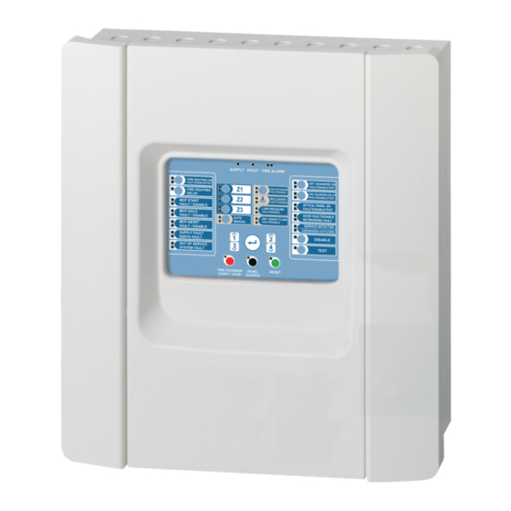
Page 7: Control Panel Overview
28. MCP Hold LEDs 13. Expansion I/O Fault/Disabled LED 29. MCP Start LEDs 14. General Disable button and LED 30. Fire Routing Delay button and LED 15. General Test button and LED 31. Fire Routing On button and LEDs ZP1-X3 Operation Manual... -
Page 8: Operator Controls And Indicators
An extinguishing released state if the red Released LED is on steady A flashing yellow LED indicates a fault that prevents the panel from entering the extinguishing activation state. A steady yellow LED indicates that the extinguishing event is disabled. ZP1-X3 Operation Manual... - Page 9 A red LED indicates that the optical warning panel or sign output is activated (to indicate the released state). A flashing yellow LED indicates a wiring fault. A steady yellow LED indicates a disablement or test. ZP1-X3 Operation Manual...
- Page 10 The disablement of some devices requires pressing the button for more than 3 seconds. (See “Disabling other extinguishing devices” on page 24 for further details.) A steady General Disable LED and the corresponding feature or device yellow LED indicates a disablement. ZP1-X3 Operation Manual...
- Page 11 The Reset button may be disabled for up to 30 minutes. Panel Silence button Yellow Silences the control panel buzzer and and LED acknowledges all current events. A steady LED indicates that all current events are acknowledged. ZP1-X3 Operation Manual...
- Page 12 Other system functions remain operational. A steady yellow LED indicates that there is no mains power and the battery power is insufficient. A flashing yellow LED indicates that the mains power is insufficient and there is no battery power. ZP1-X3 Operation Manual...
- Page 13 A flashing LED indicates that a fire routing delay countdown is in progress (fire routing activates when the configured delay elapses). Consult your system installer to determine whether the Fire routing option is configured. ZP1-X3 Operation Manual...
-
Page 14: Audible Indicators
A fire alarm in a detection zone that is not linked to the extinguishing area is indicated as follows: • General Fire Alarm LEDs: Flashing if the alarm was activated by a detector. Steady if the alarm was activated by a manual call point. ZP1-X3 Operation Manual... - Page 15 • General Fire Alarm LEDs: Flashing for detector activation. Steady for MCP activation. • Fire Sounders Start/Stop LED: Steady, as the fire sounders are activated immediately and any configured delay is bypassed. ZP1-X3 Operation Manual...
- Page 16 Released LED: Flashing rapidly during the last 10 seconds before activating the actuator to release the extinguishing agent. Flashing slowly if the actuator has been activated and the control panel is waiting for confirmation of the flow ZP1-X3 Operation Manual...
- Page 17 The MCP Hold LED turns off when the MCP Hold device is deactivated. Extinguishing released The control panel is in this state when: • The actuator output to release the extinguishing agent has been activated and the agent flow confirmation is not configured or is disabled. ZP1-X3 Operation Manual...
- Page 18 Disabled zones are indicated by a steady General Disable LED and a steady yellow Zone LED. • Disabled extinguishing sounders (and sounder outputs linked to the preactivation or released states) are indicated by a steady General Disable LED and a steady yellow Extinguishing Sounders On LED. ZP1-X3 Operation Manual...
- Page 19 Extinguishing agent pressure monitoring tests are indicated by a steady General Test LED and a steady yellow Low Pressure LED. Extinguishing released optical warning panel or sign tests are indicated by a steady General Test LED and a steady yellow Optical Panel On LED. ZP1-X3 Operation Manual...
- Page 20 (The Out of Service state is latched.) Note: When the control panel indicates out of service, the fire alarm detection in your system is inactive and your site is not protected. Contact your installation or maintenance contractor immediately to solve the problem. ZP1-X3 Operation Manual...
-
Page 21: Control Panel Operation
Public user level operation lets you: • Acknowledge a system event and silence the control panel buzzer • Cancel an active fire sounders delay • Cancel an active fire routing delay • Perform a control panel LED and buzzer test ZP1-X3 Operation Manual... - Page 22 The control panel buzzer sounds continuously. The test continues for as long as the Test button remains pressed (with an automatic timeout of 12 seconds). When the test is completed the control panel returns to its former state. ZP1-X3 Operation Manual...
-
Page 23: Operator User Level Operation
30 minutes. Consult your system installer for the time configured. When the Reset LED is steady the control panel can be reset. Stopping or restarting fire sounders To stop the fire sounders, press the Fire Sounders Start/Stop button. To restart stopped fire sounders, press the button again. ZP1-X3 Operation Manual... - Page 24 Consult your system installer to determine whether these default settings are used for your site. Extinguishing sounders can only be stopped when the control panel is in extinguishing released state (the Released LED is steady). To restart stopped extinguishing sounders, press the Extinguishing Sounders On button again. ZP1-X3 Operation Manual...
- Page 25 A steady General Test LED • A steady yellow LED for the Fire Sounders Delay button • The audible sounder test signal (3 seconds on, 5 seconds off) for the duration of the test, without any configured delay ZP1-X3 Operation Manual...
- Page 26 Disabling or enabling a zone To disable a zone, press the General Disable button, and then press the corresponding Zone button. ZP1-X3 Operation Manual...
- Page 27 The control panel will continue to report and indicate fire alarms in the extinguishing area. To disable the extinguishing event, press the General Disable button, and then press the Preactivation button. The disablement is indicated as follows: • A steady General Disable LED • A steady yellow Preactivation LED ZP1-X3 Operation Manual...
- Page 28 [2] If a safety door monitoring is not used, make sure that your installer has not configured this option or disable it to avoid preventing the extinguishing event. Testing other extinguishing devices The devices listed in Table 4 and Table 5 can also be tested at the operator user level. ZP1-X3 Operation Manual...
- Page 29 WARNING: Risk of death or serious injury. Disconnect the extinguishing agent actuator from the control panel before you issue the actuator output test command. When you confirm the test command, the actuator output is activated immediately. ZP1-X3 Operation Manual...
- Page 30 Pressing the Manual Mode button again switches the control panel back to automatic-manual mode. The Manual Mode LED turns off. In automatic-manual mode, the detection zones in the extinguishing area and the MCP Start point can generate the extinguishing event. ZP1-X3 Operation Manual...
-
Page 31: Maintenance
Keep the outside and inside of the control panel clean. Carry out periodic cleaning using a damp cloth for the outside. Do not use products containing solvents to clean the unit. Do not clean the inside of the cabinet with liquid products. ZP1-X3 Operation Manual... -
Page 32: Regulatory Information
European standards for electrical safety and electromagnetic compatibility These control panels have been designed in accordance with the following European standards for electrical safety and electromagnetic compatibility: • EN 60950-1 • EN 50130-4 • EN 61000-6-3 • EN 61000-3-2 • EN 61000-3-3 ZP1-X3 Operation Manual... - Page 33 UTC Fire & Security B.V., Kelvinstraat 7,6003 DH Weert, The Netherlands Year of first CE marking Declaration of Performance 360-3106-0399 number Product identification See model number on product identification label Intended use See DoP point 3 Essential characteristics See DoP point 9 ZP1-X3 Operation Manual...
- Page 34 ZP1-X3 Operation Manual...
Need help?
Do you have a question about the ZP1-X3 and is the answer not in the manual?
Questions and answers