Table of Contents
Advertisement
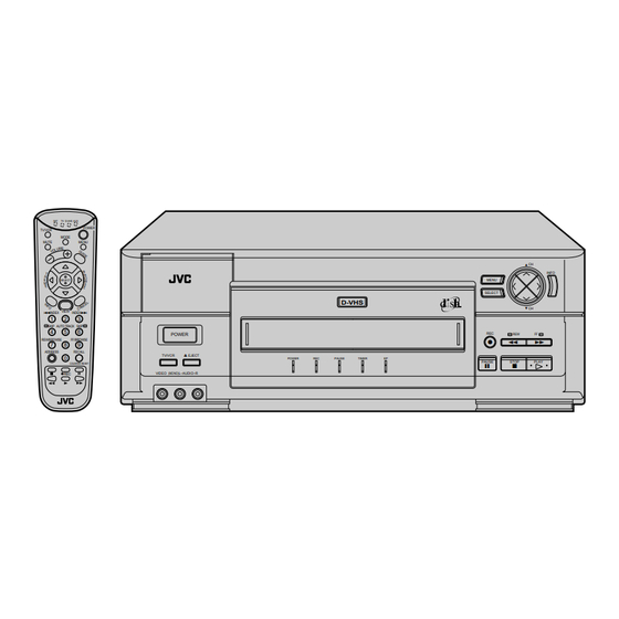
D-VHS DIGITAL SATELLITE RECORDER
HM-DSR100U
HM-DSR100DU (with Antenna Kit)
HM-DSR100RU (without Antenna Kit)
SAT
TV D-VHS AUX
POWER
TV/VCR
MODE
MUTE
MENU
E
SELECT
W
VIEW
™INDEX
INDEX£
1
2
3
SKIP
AUTO TRACK
SKIP
4
5
6
POWER
REW/BROWSE
FF/BROWSE
7
8
9
ADDRESS
RECALL
8
TV/VCR
0
COUNTER RESET
VIDEO (MONO)L–AUDIO–R
REC
D-VHS
EJECT
POWER
REC
PAUSE
INSTRUCTIONS
MENU
SELECT
TM
REC
REW
q
2
TIMER
EP
PAUSE
STOP
6
5
CH
INFO
CH
FF
3
PLAY
For Customer Use:
Enter below the Serial No. which is
located on the rear of cabinet. Retain
this information for future reference.
Model No.
Serial No.
MTP
NTSC
TM
LPT0002-0H9C
Advertisement
Table of Contents

Related Manuals for JVC HM-DSR100RU


Summary of Contents for JVC HM-DSR100RU
- Page 1 D-VHS DIGITAL SATELLITE RECORDER HM-DSR100U HM-DSR100DU (with Antenna Kit) HM-DSR100RU (without Antenna Kit) TV D-VHS AUX POWER TV/VCR MODE MUTE MENU SELECT VIEW ™INDEX INDEX£ SKIP AUTO TRACK SKIP POWER REW/BROWSE FF/BROWSE ADDRESS RECALL TV/VCR EJECT COUNTER RESET VIDEO (MONO)L–AUDIO–R...
- Page 2 Dear Customer, Thank you for purchasing the JVC D-VHS digital satellite recorder. Before use, please read the safety information and precautions contained in the following pages to ensure safe use of your new VCR. CAUTIONS CAUTION RISK OF ELECTRIC SHOCK...
-
Page 3: Important Product Safety Instructions
IMPORTANT PRODUCT SAFETY INSTRUCTIONS Electrical energy can perform many useful functions. But improper use can result in potential electrical shock or fire hazards. This product has been engineered and manufactured to assure your personal safety. In order not to defeat the built-in safeguards, observe the following basic rules for its installation, use and servicing. - Page 4 1. Accessories To avoid personal injury: • Do not place this product on an unstable cart, stand, tripod, bracket, or table. It may fall, causing serious injury to a child or adult, and serious damage to the product. • Use only with a cart, stand, tripod, bracket, or table recommended by the manufacturer or sold with the product.
-
Page 5: Table Of Contents
Important Product Safety Instructions ... ii Chapter 1: Introduction ... 1-1 Welcome! ... 1-1 Highlights ... 1-1 About Satellite Television ... 1-2 About D-VHS ... 1-3 Unique All-In-One Design ... 1-3 If You Are Installing Your System Yourself ... 1-3 Features Overview ... - Page 6 User and Installation Guide Chapter 5: VCR Features ... 5-1 Cassettes and Recording Modes ... 5-1 Simple Playback and Recording ... 5-1 Playback Features ... 5-6 Recording Features ... 5-17 Using Caller ID ... 5-20 Event Timers ... 5-22 Editing to or from Another VCR ... 5-33 Editing from a Camcorder ...
-
Page 7: Chapter 1: Introduction
World Wide Web. For warranty service, or for information about the features and operation of the HM- DSR100DU/RU call JVC at 1-800-252-5722. For more information on JVC products, see JVC's home page at http://www.jvc.com on the World Wide Web. IGHLIGHTS You have purchased the most advanced, easy-to-use satellite dish system available today. -
Page 8: About Satellite Television
User and Installation Guide BOUT ATELLITE ELEVISION Satellite television uses satellites orbiting in geosynchronous orbit over the Earth to deliver television and audio programming. "Geosynchronous" means that the satellites stay aligned over one place on the surface of the Earth. Once your satellite antenna is aimed at the satellites, the antenna does not have to move to follow the satellites. -
Page 9: About D-Vhs
D-VHS cassettes. Playing back D-VHS recording made on other D-VHS VCRs: D-VHS recordings made on other VCRs may not playback on your JVC VCR. This is because other D-VHS VCRs may record satellite signals from a system that is not compatible with your DVB/MPEG II DISH system. -
Page 10: Features Overview
User and Installation Guide EATURES VERVIEW For more detailed information, see Chapter 2 – The Parts of Your System. TANDARD EATURES Recorder Remote Control Simple Menu Operation On-Screen Program Guide Themes Favorites Lists System/Parental Locks Electronic Mail Audio-only Programming CD-Quality Sound DVANCED EATURES Event Timers... -
Page 11: Available Services
VAILABLE ERVICES Your system is capable of receiving a wide range of exciting and entertaining services. The available services encompass an unlimited variety of interests, including movies, sports, news, music, shopping, comedy, and more. Call the Service Center for more information on any of these. -
Page 12: Quick Start Tips
User and Installation Guide UICK TART This is a quick reference to start common procedures: Change Channels Open the Main Menu Open the Program Guide Open the Browse Banner Order a Pay Per View Program See the last channel you viewed Select a program based on a theme See information about... -
Page 13: Chapter 2: The Parts Of Your System
The Parts of Your System ECORDER ECORDER RONT ANEL ACCESS DOOR POWER TV/VCR EJECT VIDEO (MONO)L–AUDIO–R The recorder front panel provides control buttons, plus access to the Smart Card slot. CCESS The Smart Card slot is behind this door. The recorder is shipped with the Smart Card pre- installed in this slot. - Page 14 User and Installation Guide OWER IGHT The POWER light illuminates when the recorder is turned ON. This light flashes when the recorder memory contains unread mail messages. IGHT The REC light illuminates while a tape is being recorded. This light blinks during Instant Timer Recording (ITR). AUSE IGHT The PAUSE light illuminates when recording or playback is paused.
- Page 15 TV/VCR B UTTON Press the TV/VCR button to select the signal source that your TV receives. Choose TV position to watch TV or to watch one program while recording another. Choose VCR position to watch a tape, monitor a recording, or watch a satellite or local TV broadcast being received by the recorder.
-
Page 16: Back Panel
User and Installation Guide ECORDER ANEL AC`IN PHONE JACK The back panel of the recorder provides the connectors that you use to wire the recorder to all the other components and equipment that you may use. Depending on the installation setup that you use, you may not use some of these connectors, but they are provided to support any desired setup. -
Page 17: S-Video Output
RF O VHF C ONNECTION The recorder sends non-stereo output through this connector. If you are connecting cable TV or a broadcast TV antenna to the recorder, use this connection to connect to the TV for good picture and good non-stereo sound. -
Page 18: Dolby Digital Output )
User and Installation Guide AC-3 (D OLBY IGITAL By connecting this output terminal to an external decoder, you can enjoy Dolby Digital (AC-3) 5.1-channel surround sound when viewing appropriately encoded satellite broadcasts or recorded tapes. Dolby, Dolby Digital, AC-3, Dolby Pro Logic are registered trademarks or Dolby Laboratories Licensing Corporation. -
Page 19: The Remote Control
EMOTE ONTROL This section describes the features of your remote control. For details on using the remote, turn to Using the Remote Control on page 3-1. The remote control lets you access all the features of your system, including changing channels, using the menu system and operating the built-in VCR. - Page 20 User and Installation Guide UHF R BOUT THE EMOTE The UHF remote sends ultra-high frequency radio signals to a UHF antenna that is connected to the back of the recorder. Because UHF signals travel through solid objects, you can use the remote to control the recorder from another room, or even from another floor in the building.
-
Page 21: Remote Buttons
EMOTE UTTONS TV/VCR B UTTON Depending on how you wire your system together, the does the following: In SAT (Satellite) mode, the connected to the RF or VHF output between satellite TV and broadcast or cable TV. However, the easier way to view both satellite programming and local broadcast programming (see Local TV Link on page 3-13 for information). - Page 22 User and Installation Guide UTTON Press the Mute button to temporarily activate the mute function on your TV. Press the Mute button again to restore the sound. This button works only if you have programmed the remote to Note: control a TV or a stereo amplifier. The at the corresponding electronic component, not at the recorder.
-
Page 23: Select Button
When viewing a program, press the change channels. When you have the Browse Banner arrow button to view the Browse Banner available during playback) When a menu offers you a list of choices, press the arrow button to bring more choices into view. When you have the Program Guide arrow button to move the highlight through the channels. - Page 24 User and Installation Guide ANCEL UTTON Press the Cancel button to cancel the current procedure and to return to the previous menu or to viewing your program. UMBER UTTONS You can use the number pad buttons for several purposes: When viewing a program or when the open, enter the 3-digit channel number and press the button to change immediately to that channel.
- Page 25 ECALL UTTON OUNTER With the remote in the SAT mode, press the the last channel you were watching. Press repeatedly to alternate between the last two channels that you viewed.With the remote in the D-VHS mode, and if there is a tape loaded in the recorder, press the Counter Reset button to change the current tape counter reading to "0:00:00".
-
Page 26: The Satellite Antenna
User and Installation Guide ATELLITE NTENNA The satellite antenna collects the signals transmitted from the satellites. A coaxial cable (or cables) carries these signals to the receiver (or receivers), where they are decoded and processed so you can view television programming. -
Page 27: Chapter 3: Getting Started
Getting Started SING THE EMOTE NSTALLING ATTERIES IN THE The remote control is shipped with four AAA batteries, packaged separately. When you replace old batteries, you should replace all four batteries. Use four batteries of the same grade, for example, alkaline or carbon zinc, and do not mix batteries of different grades. - Page 28 User and Installation Guide HANGING ODES ON THE Use the button to set the remote to control other electronic components, such as your Mode TV. See Mode Button on page 2-9 for more information. To change modes, do the following: Press the button on the remote Mode...
- Page 29 5. Press the Address button to save the new address in the remote memory. If the address you entered is valid for your remote, the SAT mode light blinks three times. 6. If the recorder is ON, turn it OFF using the recorder Power button.
-
Page 30: Turning On The System
User and Installation Guide URNING N THE YSTEM 1. Turn ON the TV and any other installed equipment. 2. Turn ON the recorder. The power light on the recorder front panel illuminates. The remote must be in SAT mode to Note: use it to turn ON the recorder. -
Page 31: Canceling A Procedure
ANCELING A ROCEDURE Sometimes, when you are trying to make changes via the menus, you may want to stop and start over. From any menu or screen, you can press the until you return to your program. If you do not do anything in a menu for several minutes, such as press a button or select an option, the menu automatically closes. -
Page 32: System Menu Structure
User and Installation Guide BOUT ENUS AND THER We designed the menus to make programming your recorder and selecting services quick and easy. The recorder displays the menus on your TV screen (“on-screen”). You use menus to communicate with the recorder and use the recorder features, such as setting security locks, selecting a program, or defining a Favorites List. -
Page 33: About Menus And Other Multiple-Choice Screens
About Menus and Other Multiple-Choice Screens ISPLAYING ENUS You can use either of two methods to open the menus. Open the , then open any of the other menus from the Main Menu Press the appropriate button on the remote to immediately open the desired menu. PTIONS A typical menu option looks like this: or this:... - Page 34 User and Installation Guide ULTIPLE HOICE ISTS When you select a choice from a list, the recorder does not apply the change until you select option. If you do not want to save any changes, select the Save discard all changes made in the menu. There are two types of lists: single selection and multiple selection.
-
Page 35: Getting Started
About Menus and Other Multiple-Choice Screens When you highlight a choice in a single-selection list, it typically appears as shown below: Languages English Spanish French German Italian Japanese When you select a choice in a single-selection list, the choice is marked as shown below: Languages English... -
Page 36: The Main Menu
User and Installation Guide provides access to all the features available in the menus. To open the Main Menu , press the button. The Menu Menu Opens Program Guide Screen Opens Theme Categories Menu Opens Mail Menu Opens Favorite Lists Menu Exit Viewed Program Press the... -
Page 37: Installation
NSTALLATION This option displays the Installation and Setup you are initially setting up your system. Use the Point Dish and Signal Strength Transponder refers to the channel transponder numbers that this unit receives. Transponder numbers are automatically displayed. ZIP Code refers to the postal number code of the region where you live. Enter the ZIP Code with the number pad buttons in Step 6 of Finding the Direction and Elevation on page 6-10. - Page 38 User and Installation Guide Select Picture Size: You can choose the picture format if a program is transmitted in both standard (4x3) and wide-screen (16x9) formats. You can use the 16x9 format only if you have a wide-screen TV that supports the 16x9 format. Decide how to order the channel numbers while you are displaying the You can display the channel numbers in ascending or descending order.
-
Page 39: Local Tv Link
TV L OCAL The Local TV Link feature allows you to view your local broadcast or cable channels via your system. Once you get the channels set up, you can select and view those channels through the Program Guide any of the satellite channels. The quality of the audio and video you receive on local broadcast channels depends on the distance and terrain (hilly or flat) between the broadcast station and where you live, and the placement and quality of the broadcast TV antenna... - Page 40 User and Installation Guide DDING OCAL OR ABLE To add local broadcast or cable channels, do the following: button until the remote 1. Press the Mode is in SAT mode. 2. Press the button to open the Menu Main Menu 3.
- Page 41 8. Select the Choose option. Press the arrow and arrow button to highlight the Choose and press the Select display the Choose Local Channel 9. Notice that the first time you display the Choose Local Channel screen, the only channel in the Selected Local Channels list is channel 000.
- Page 42 User and Installation Guide 13.Press the Left arrow button to move the highlight to the keypad area. 14.Use the arrow buttons to highlight a letter. Press Select . Repeat to spell out the name of the channel. You can enter up to five characters for the channel name.
- Page 43 19.Once you are finished, select the option. The recorder will display the Choose Local Channel screen. The channel that you have just added should now appear in the Selected Local Channels list. 20.Repeat steps 10 through 19 until all desired channels are added.
- Page 44 User and Installation Guide 7. Press the Left arrow button twice to move the highlight to the Selected Local Channels list. Either: Use the Down button to highlight the channel you want to delete. Press Select . Repeat until all desired channels are deleted.
- Page 45 DITING THE AME OF A HANNEL If you have entered the wrong channel name or want to add a channel name for a channel (except ) that is on the Ch 000 1. Press the button until the remote Mode is in SAT mode.
- Page 46 User and Installation Guide 9. Press the Left arrow button to move the highlight to the keypad area. 10.Use the arrow buttons to highlight a letter. Press Select . Repeat to spell out the name of the channel. If necessary, select the space to insert a space in the channel name or the...
-
Page 47: Chapter 4: Using The System
Using the System BOUT THE ROGRAM Program Banner is displayed for a few seconds at the top and bottom of the TV screen every time you change the channel, begin playback of a recording, or press the on the remote. The top Program Banner are viewing. - Page 48 User and Installation Guide While recording a program, the information, including a graphical tape position indicator. At the start of playback, the being currently played, as well as the current playback status. Depending on the recorded program, the following information may be displayed. ROGRAM ANNER URING...
-
Page 49: About The Browse Banner
BOUT THE ROWSE You can use the Browse Banner without removing the current program from view; and, create an event timer. information is displayed at the top and bottom of your TV screen and Browse Banner includes the items in the following pictures: ROWSE ANNER FOR ATELLITE... - Page 50 User and Installation Guide PENING THE ROWSE ANNER To open the Browse Banner button. IEWING ANNER NFORMATION FOR To view Browse Banner 1. Press the button until the remote is in Mode SAT mode. 2. Press the arrow button to display the Right for the current program.
-
Page 51: About The Browse Banner
HANGING HANNELS IA THE If you are browsing and see a program that you would like to view, do the following to change to the new channel: 1. Make sure the channel you want to view is displayed in the lower portion of the Browse Banner 2. -
Page 52: About The Program Guide
User and Installation Guide BOUT THE ROGRAM provides a complete listing of the available channels and programs. Program Guide You must add your local broadcast or cable channels to the Note: See Local TV Link on page 3-13. However, the "prime time"... - Page 53 Indicates that the last viewable time period is in view (you cannot display a time later than this). This display is normally blank with two arrows. When it is not blank, it shows: The number of hours being entered on the remote control number pad. Press the backward that number of hours.
- Page 54 User and Installation Guide CANNING HROUGH HANNELS You can scan through the available channels in the ming is available. To do this, do the following: Either: Enter the desired 3-digit channel number. Optional: Press the Press the Down arrow button to highlight the desired channel.
-
Page 55: Using The System
HANGING HANNELS IA THE To change to a new channel using the 1. Press the button until the remote is in Mode SAT mode. 2. Press the button to open the Guide Guide Enter the desired 3-digit channel Either: number using the number pad buttons. Then, press to change to the new Select... - Page 56 User and Installation Guide IEWING NFORMATION BOUT If you want more information about a program listed in the 1. Press the button until the remote is in Mode SAT mode. 2. Press the button to open the Guide Guide 3. Highlight the desired program using the arrow buttons on the remote control.
-
Page 57: About Themes
BOUT HEMES The system allows you to list and select programs according to the theme of their contents. For example, you can list just movies or just sports. You can then quickly list programs based on that theme, and select the program you want without having to search through all the channels. - Page 58 User and Installation Guide ELECTING A ROGRAM IN THE You can change to a program in the 1. Press the button until the remote is in Mode SAT mode. 2. Use the Page Up Page Down (or the Fast Forward to speed your search for the desired program.
-
Page 59: Ordering Pay Per View Programs
RDERING A pay per view program is a program that you order and pay a small fee to view once. There are many types of programs available through the pay per view service, such as movies, sports, comedies, and musicals. You can find out what pay per view programs are available by viewing the Program Guide the Program Guide on page 4-6). -
Page 60: Favorites Lists
User and Installation Guide 4. At the Confirmation Screen: Select the option again to confirm Either: the purchase. The fee will appear on your invoice. Select the option or the cancel the purchase. Note: You cannot cancel previously ordered pay per view programs using this procedure. To order through the Service Center: Call the Service Center to order the pay per view program. - Page 61 REATING OR ODIFYING A You can add channels to, and remove channels from a Favorites List. 1. Press the button until the remote is in Mode SAT mode. 2. Press the button to open the Menu Main Menu 3. Select the option.
- Page 62 User and Installation Guide 7. In the Channels list, highlight the channel you want to add to your Favorites List. Either: Use the Down to bring the desired channel into view. Use the number pad buttons to enter the channel number. Note: When entering a channel number that has fewer than three digits (for...
- Page 63 HANGING THE AME OF A Since the lists are initially named "LIST 1," LIST 2," etc., you may want to give them more meaningful names. "MOM," "DAD," or "MYFAV" are all possible Favorites Lists names. 1. Press the button until the remote is in Mode SAT mode.
- Page 64 User and Installation Guide AKING A AVORITES When a Favorites List is active, the recorder displays only the channels in that list. However, you can still view a channel not on the list by entering the 3- digit channel number using the remote number pad buttons, or by selecting a program on that channel using the When changing channels to a channel number that has fewer than three Note:...
-
Page 65: Security Features
ECURITY EATURES BOUT ECURITY EATURES Security features let you make sure your system is being used the way you want it to be used. You can use two levels of security: You can lock your system, so that only those who know the password can access locked features (see below). - Page 66 User and Installation Guide To lock the system, you must set a password: When you lock the system, you must enter and verify a 4-digit number password, which you make up. Later, you must enter the same password to unlock the system, make changes to locked features, or access locked programs.
- Page 67 If the system is locked , enter the system password using the number pad buttons. As soon as you enter the fourth digit of the password, the system highlights the option. Press the Select button. 5. Select the Channel Locks 6.
- Page 68 User and Installation Guide REATING OR ODIFYING Do the following to lock programs with certain rating or extended rating (content) codes. Only someone who knows the password can then view these programs. See Glossary on page A-7 for a definition of each of the rating codes. Parents beware, the rating and extended rating (content) codes that the system uses for program locks reflect the codes that the original program providers assigned to the programs.
-
Page 69: Panel Buttons
7. Highlight the expanded rating code(s) to lock, if desired. Press the Select button. 8. To unlock a rating code, highlight the code and then press the Select 9. Select the Save option to save the changes. If the system is not locked lock you just created into effect. - Page 70 User and Installation Guide 5. In the Parental and System Locks select the Front Panel Lock 6. At the Lock Front Panel Buttons select the Lock option. If the system is not locked the lock you just created into effect. See Locking the System on page 4-25.
- Page 71 1. Choose a channel or a program that you have locked. The recorder displays an ATTENTION message telling you that the item is locked and prompting you to enter the system password. If the system is locked , enter the system password using the number pad buttons.
-
Page 72: Unlocking The System
User and Installation Guide 3. Select the Locks option. If the system prompts you for a password, it has already been locked. 4. Select the Lock System option. The recorder displays a message prompting you to enter the system password. Note: If this option says "Unlock System"... - Page 73 4. Enter the system password using the number pad buttons. As soon as you enter the fourth digit of the password, the system highlights the Press the Select button. 5. Select the Unlock System Note: If this option says "Lock System" instead, then the system has already been locked.
- Page 74 User and Installation Guide 7. Enter the new password using the number pad buttons. As soon as you enter the fourth digit of the password, the system highlights the option. Go on to the next step. Either: Select the option. If you do not want to change the password, select the Cancel...
- Page 75 1. Press the Mode button until the remote is in SAT mode. 2. Press the Menu button to open the Main Menu 3. Select the System Setup 4. Select the Installation option. 5. Select the Factory Defaults 6. Select the option.
-
Page 76: Electronic Mail
User and Installation Guide LECTRONIC You may occasionally receive electronic mail from the Service Center via the satellite signal. If your recorder is powered on and the LED is blinking on the front panel, you have mail. This mail typically tells you about upcoming events, programs, special offers, and system changes. -
Page 77: Software Upgrades
5. If necessary, press the button to view all of the message. Either: After you are finished reading, select the Delete option to delete the mail message. Select the Save option to save the message. OFTWARE PGRADES Occasionally, the Service Center may send you, at no extra cost, a list of newly available system features. - Page 78 User and Installation Guide 6. Press the Left arrow button to move the highlight to the Without my permission option. 7. Press the Down arrow button to select either the Without my permission option to have upgrades automatically downloaded to your system or the before downloading option to have upgrades downloaded with your...
-
Page 79: Viewing Programs In Other Languages
Viewing Programs in Other Languages IEWING ROGRAMS IN You can change the language of the programs you view by using the To change to an alternate language, do the following: An alternate language may not be available for all programs. Some programs, such Note: as movies, indicate at the start of the program whether an alternate language is available. - Page 80 User and Installation Guide Either: Select the Save option to save your language choice. The recorder returns to the System Setup menu. Press the Cancel button to cancel any changes you have made in the Audio menu. The recorder displays a confirmation screen.
-
Page 81: Setting Up Channel Order
ETTING HANNEL You can set up the Program Guide example, from top to bottom, 122, 140, 170, 172, 200, ...) or in descending order (for example, from top to bottom, 200, 172, 170, 140, 122, ...). If you do not specify a channel order, the recorder automatically displays the Note: channels in ascending order. -
Page 82: Diagnostic Tests
User and Installation Guide IAGNOSTIC ESTS are available for you to verify that the main components of your system Diagnostic Tests are working correctly. The components: front panel, remote control, dish signal, telephone connection, and the main unit (that is, the recorder). The Customer Service representative may ask you to perform some or all of these tests while trouble-shooting problems. - Page 83 2. Press any front panel button on your recorder, except the panel is working correctly, the recorder briefly displays a message that says "Front Panel button." If the front panel is not working correctly, the recorder displays a failure message. See the Diagnostic Test section of the Problems and Solutions Tables on page A-18.
- Page 84 If the main unit is working correctly, the recorder displays a message that says "Main Unit OK." If the main unit is not working correctly, the recorder displays a failure message. In this case, call the JVC Service Center for assistance.
-
Page 85: Programming The Remote Control
Programming the Remote Control ROGRAMMING THE EMOTE You can program the remote to control not only the recorder, but also your TV, and cable box or amplifier. This remote supports most brands and models; however, there may be some brands or models that it does not support. You can program the remote to control a maximum of four different electronic components. - Page 86 User and Installation Guide 5. Use the number pad buttons to enter the first 3-digit code listed for your equipment brand in the table. The mode light stops flashing and stays lit. If you are entering a code for the AUX mode, you Note: have to enter a four-digit code.
- Page 87 UHF signals, so it will not respond to signals from distant remotes. Attenuators are available at some electronics supply and satellite TV stores or from JVC parts at 1-800-882-2345. The JVC part number for this attenuator is T500511.
- Page 88 User and Installation Guide 4. Press the Down arrow button to set the remote to the next code. The Down and the arrow button scans forward. When the correct code is reached, the equipment (whether VCR, TV, or other) powers OFF. 5.
- Page 89 Programming the Remote Control ETERMINING THE URRENT You can find out which code is currently set for each remote mode. 1. Press the Mode button on the remote until the appropriate mode light is flashing rapidly. button twice. 2. Press the Address For SAT mode, the mode light flashes the number of times that matches the recorder address.
-
Page 90: Equipment Codes For Programming The Remote
User and Installation Guide QUIPMENT ODES FOR ELEVISIONS Note: Not all the codes listed in these tables are valid for all remote controls. Akai 032, 070 Alba A-Mark Amstrad Anam 009, 021, 041, 120, 121 005, 006, 019, 020, 120, Archer Audiovox Bauer... - Page 91 Equipment Codes for Programming the Remote Aiwa 088, 122, 123, 124 Akai 013, 014, 015, 016, 017, 018, 019, 020, 068 Alba Amstrad Audio Dynamics 100 Broksonic Bush Candle 080, 092, 093 Canon 042, 054 Capehart 043, 046 Citizen 091, 092, 093 Craig 091, 108 Curtis Mathes...
- Page 92 User and Installation Guide NOTES Page 4-46...
-
Page 93: Chapter 5: Vcr Features
VCR Features IMPLE LAYBACK AND This recorder has a built-in VCR which will let you play back tapes that have been recorded in the D-VHS (bit stream) and VHS (analog) formats, as well as make your own recordings in the D-VHS and VHS formats. D-VHS cassettes and VHS can be used in the HM- DSR100DU/RU. -
Page 94: Simple Playback
User and Installation Guide IMPLE LAYBACK To play back a D-VHS or VHS tape, do the following: 1. Load a cassette into the cassette loading slot. The VCR's power comes on automatically. If the cassette's record safety tab has been removed, playback begins automatically. -
Page 95: Simple Playback And Recording
IMPLE ECORDING Remember that both digital and analog signals can be recorded on a D-VHS tape, and that only analog signals can be recorded on a VHS tape. Follow the following procedure to record on a D-VHS or VHS tape: 1. - Page 96 User and Installation Guide 4. Use the arrow buttons to select Bit Stream (D-VHS) Recording "ON" or "OFF" in the Mode section of the VCR Setup screen. Refer to the next page for further instructions. Bit Stream (D-VHS) Recording is possible only when you record a satellite channel using a D-VHS cassette, and when Bit Stream (D-VHS) Recording setting is set...
-
Page 97: Tape Speed
(D-VHS) R ETTING THE TREAM Remember that a D-VHS tape can record both bit stream and analog signals, while a VHS tape can record only analog signals. To record on a D-VHS or VHS tape, do the following: 1. Press the Mode button until the remote is in the SAT mode. -
Page 98: Playback Features
User and Installation Guide LAYBACK EATURES To make finding and playing the taped program or scene you want as easy as possible, the recording is equipped with a variety of convenient playback features. PEED EARCH Best with: Analog recordings. To search for a location with a high-speed visual playback picture, do the following: 1. -
Page 99: Skip Search
3. To stop, press the Stop button at any time. Notes: When playing back a bit stream recorded tape, the program information for the program being fast forwarded is displayed on the TV screen for about 5 seconds, but the playback picture may appear frozen (still picture) or block noise may appear during search. -
Page 100: Index Search
User and Installation Guide NDEX EARCH Best with: Bit stream and analog recordings. Index codes are placed on the tape at the start of each recording. You can find and automati- cally play back from the start of any recording using the Index Search function. Do the following: 1. -
Page 101: Still Picture
ICTURE TILL RAME Best with: Analog recordings. To "freeze" the playback picture and view it one frame at a time, do the following: 1. Press the button until the remote is in Mode the D-VHS mode. 2. During playback, press the If there is vertical jitter, use the arrow button to correct the picture. -
Page 102: Manual Tracking
User and Installation Guide ANUAL RACKING Best with: Bit stream and analog recordings. Once playback begins, the recorder's automatic tracking functions is engaged. If noise appears in the picture, you can override this and make the adjustment manually by doing the following: 1. -
Page 103: Video Stabilizer
IDEO TABILIZER Only with: Playback of analog recorded tapes. You can correct vertical vibration when playing back unstable EP recordings that were made on another VCR. To turn this function on for automatic correction of vertical vibration, do the following: 1. - Page 104 User and Installation Guide UPERIMPOSE This function, which can be switched on or off, determines whether or not the recorder's operational indicators will appear on the TV screen. Do the following: 1. Press the button until the remote is in Mode the SAT mode.
- Page 105 ELECTING THE OUNDTRACK Only with: Playback of analog recorded tapes. The recorder can record two soundtracks simultaneously (Hi-Fi and Normal) and play back the selected one, or both together. To choose, do the following: 1. Press the button until the remote is in Mode the SAT mode.
-
Page 106: Counter Reset
User and Installation Guide OUNTER ESET To reset the counter reading to zero, do the following: 1. Press the button until the remote is in Mode the D-VHS mode. 2. Press the Counter Reset The counter is reset, and the new counter reading is displayed on the TV screen. -
Page 107: Playback Features
5. Press the arrow buttons to move the highlight to Save 6. Press the Select button to save all changes. Note: If Counter Memory is turned on, "Memory" appears in the the TV screen. EPEAT LAYBACK To repeatedly play the same tape 20 times consecutively, unattended, do the following: 1. - Page 108 User and Installation Guide UNCTION EMORY The Next Function Memory "tells" the recorder what to do immediately after rewinding. Before continuing, be sure that the recorder's tape is stopped. (a) For Automatic Start of Playback after Tape Rewind... press the button, then press the Rewind button within 2 seconds.
-
Page 109: Recording Features
ECORDING EATURES Various features are provided to make video taping an easy and sure process. ECORDING ROGRAM To watch a broadcast or cable TV channel while recording another program using the built- in VCR, do the following: 1. During recording, press the If you are using the RF connection (see p. - Page 110 User and Installation Guide SAP (S TEREO AND ECOND The recorder's built-in MTS decoder enables reception of local broadcasts with Multi- channel TV Sound. To Record Stereo Programs... simply follow the basic recording procedure. To Listen To Stereo Soundtrack During Recording...
-
Page 111: Instant Timer Recording
NSTANT IMER ECORDING This "on the fly" timer lets you record from 30 minutes to 6 hours (selectable in 30-min. increments), and shuts the recorder off after recording is finished. To activate, do the following: 1. During recording, press the on the recorder's front panel at any time to engage the ITR. -
Page 112: Using Caller Id
User and Installation Guide SING ALLER Your system can display caller identification: the name and telephone number of the caller for your incoming telephone calls. However, caller ID only displays information your telephone company provides. You may not get all caller IDs, and some callers may block caller ID. - Page 113 8. Select the Save option. 9. If you have not already done so, call your telephone company to activate caller ID. When the recorder detects an incoming call, it displays an on-screen message showing the caller's name and telephone number. If you receive a telephone call while you are watching a program or using the , the recorder displays a message similar to the following at the bottom of your Banner...
-
Page 114: Event Timers
User and Installation Guide VENT IMERS Event timers are a kind of alarm clock, reminding you when a program you want to watch is about to start. You may set three types of event timers: VCR Event Timer Auto-Tune Event Timer Reminder Event Timer Before you can use a VCR Event Timer, you must do the following: Insert a rewound tape on which you want to record. - Page 115 In this section, "event" means a program such as a TV show, movie, sports event, or Note: pay per view program. Three minutes before an event timer is to execute, the recorder displays a small blinking icon on your TV screen to remind you that an event timer is scheduled to begin.
- Page 116 User and Installation Guide REATE AN VENT IMER You can set the recorder's timer to automatically record a program by choosing the program through the Browse Banner Load a cassette into the cassette loading slot. Make sure the record safety tab is intact. If the tab is missing, cover the hole with adhesive tape before inserting the cassette.
- Page 117 5. Press the Down arrow button to highlight the desired timer frequency. Next press the Select button and then press the Right arrow button. 6. Press the Down arrow button to select "Mode". Then press the button. Select "D-VHS" when recording a satellite broadcast on a D-VHS tape.
- Page 118 User and Installation Guide REATE A ANUAL VENT To program the recorder's built-in timer manually, do the following: 1. Press the button until the remote is in Mode the SAT mode. 2. Load a cassette into the cassette loading slot. Make sure the record safety tab is intact.
- Page 119 8. Press the Down arrow button or number buttons to select the desired channel. Next press the Select and then press the Down arrow button. 9. Press the Left Right arrow button to select "Mode". Then press the button. Select "D-VHS" when recording a satellite broadcast on a D-VHS tape.
- Page 120 User and Installation Guide 15.Press the number buttons to input the date under Mo./Day. To input a one-digit number, be sure to insert a zero first. Step 15 not necessary if you selected "Mon-Fri" or "Daily" in step 7. If you selected "Weekly" in step 7, press the Down arrow button to select the Day, and press the...
- Page 121 CHEDULING ONFLICTS If you try to create event timers for overlapping events, the recorder displays a menu that says, "WARNING: Event Timer Scheduling Conflict," and shows the dates and times of both events. The recorder also displays this menu if an event time has changed, causing the event timer to overlap a previously created event timer.
- Page 122 User and Installation Guide 3. Select the Timers option. The Management screen will be displayed. 4. Press the Left arrow button to highlight the first event timer in the event timers list. 5. Press the Down arrow button to highlight the event timer that you want to delete.
- Page 123 HANGES FTER To make changes after you have set event timers, do the following: 1. Perform steps 1 - 6 of Deleting an Event Timer described on page 5-29 and 5-30. 2. Press the arrow button, then the Right arrow button to highlight Down option.
- Page 124 User and Installation Guide 8. Select the Create Timer option to save the event timer, and press the 9. Press the Power button to turn the recorder off. The TIMER light on the recorder's front panel will illuminate. EVIEWING VENT IMERS You can display a list of scheduled event timers at any time, using the menu.
-
Page 125: Editing To Or From Another Vcr
DITING TO OR FROM You can use the recorder as the playback unit or the recording unit to edit from VHS to VHS. It is also possible to use the recorder as the playback unit to edit from D-VHS to VHS. It is not possible to edit from D-VHS to D-VHS by connecting to an external D-VHS recorder. -
Page 126: Editing From A Camcorder
User and Installation Guide DITING FROM A AMCORDER You can use a camcorder as the playback unit and the recorder as the recording unit to edit rough footage into personal videos. Do the following: 1. Connect the camcorder's VIDEO OUT and AUDIO OUT connectors to the recorder's VIDEO IN and AUDIO IN connectors using the supplied Audio/Video cable. -
Page 127: Chapter 6: Starting Your Installation
Starting Your Installation NTRODUCTION NFORMATION If you do not want to install your system yourself, you can have it installed by a professional. Call the DISH Network Service Center at 1-800-799-7175 for information about installation in your area. If you do intend to install your system yourself, this chapter provides installation procedures. The procedures are relatively simple, but do require some skill in construction-related tasks. -
Page 128: Summary Of Installation
1. Unpack the satellite antenna*, recorder, and parts (see pages 6–3 through 6–5) and the optional installation kit, if you purchased one (see page 6–7). *Supplied with HM-DSR100DU. Sold separately for HM-DSR100RU. 2. Review "What You Need" (see pages 6–6 through 6–8). Connect the recorder to your TV set. -
Page 129: Before You Start Installation
EFORE TART NSTALLATION NPACKING AND HECKING As you unpack the system, confirm that all the parts are included. See Package Contents below for a list of the included components. Note: Keep the shipping materials in which these items are packed, in case you ever need to return them. -
Page 130: Components Of The Satellite Antenna
User and Installation Guide OMPONENTS OF THE The following pictures are not to scale. Note: The fully assembled satellite antenna looks like this. Following are descriptions of each piece of the satellite antenna. LNBF (L OISE LOCK The "dish" focuses the signals transmitted from the satellites onto the LNBF. The LNBF amplifies the signals, converts the whole "block,"... - Page 131 Components of the Satellite Antenna The dish reflects and focuses the signals from the satellites onto the LNBF. Flathead bolts with nuts attach the dish to the support arm bracket. LNBF S CREW AND ASHER The LNBF screw and washer attach the LNBF to the end of the support arm.
-
Page 132: What You Need
User and Installation Guide EED TO Because you will make modifications to the location where you mount the satellite antenna, you should be somewhat familiar with and be able to safely perform the following procedures. You should be able to use a plumb line or level to set both horizontal and vertical sur- faces. -
Page 133: Optional Installation Kit
Sledgehammer or small fence post driver Drill and 1/2 inch drill bit - long enough to drill through the exterior wall of your building Compass * Silicone sealant (for sealing drill holes) * You will need additional tools and materials, depending on the type of surface on Note: which you mount the antenna. -
Page 134: Installing Batteries In The Remote
User and Installation Guide Compass Silicone sealant Tools, such as drills or screwdrivers, are not included in the Installation Kit. NSTALLING ATTERIES IN THE Four AAA batteries, packaged separately, are included with the remote control. See Installing Batteries in the Remote on page 3-1 for this procedure. ETTING THE EMOTE DDRESS... -
Page 135: Finding The Satellites
INDING THE ATELLITES Before you can decide on the mounting location for the antenna, you must determine the approximate location of the satellites. Then you must find a mounting site that provides an unobstructed signal path from the satellites to the antenna. Compass Recorder with built-in satellite receiver, connected to a TV ETERMINING THE... - Page 136 User and Installation Guide INDING THE IRECTION AND When determining the approximate location of the satellites, you need to find the azimuth (South, Southeast, or Southwest direction to the satellites) and elevation (angle up to the satellites) from your location. "Azimuth" is also called "direction." This Guide uses the term "direction". Finding the satellites is easy.
- Page 137 INDING A LEAR INE OF "Finding a clear line of sight" means finding a location for the satellite antenna so that its view of the orbiting satellites is unobstructed by trees, buildings, or any other obstructions. This includes making sure that sapling trees are not likely to grow up or out into the line of sight.
- Page 138 User and Installation Guide 3. Use the elevation number to find out how high the satellites are in the sky from your location. You know that vertical is 90°, and horizontal 0°, and halfway in between is 45°. Stand close to where you plan to mount the satellite antenna and face in the direction that you marked for the direction to the satellites.
-
Page 139: Discussion Of Potential Mounting Sites
Discussion of Potential Mounting Sites ISCUSSION OF OTENTIAL When you are surveying your property for appropriate sites for the satellite antenna, keep in mind that you can mount the satellite antenna on a variety of surfaces: brick, cinder block, wood, some sidings, rooftop, or a pole. Since installing the satellite antenna may involve drilling into the wall or roof of your building, or digging a hole and using cement, you should be very confident of the location before beginning installation. - Page 140 User and Installation Guide Place the satellite antenna as close to the recorder as possible. Use no more than 100 feet of cable between the recorder and the satellite antenna, unless you install a line amplifier to boost the signal. Otherwise, the system is more likely to lose the signal during periods of rain, snow, or heavy cloud cover.
- Page 141 Discussion of Potential Mounting Sites OUNTING THE NTENNA ON Materials Required 4 wall anchors, 1/4” 4 machine bolts, 1/4” x 3” "Brick" is defined as a solid brick wall or other structure. This does not include brick facing that is used on some buildings over the main structure. If you are mounting the satellite antenna on brick facing, see Mounting the Antenna on Siding on page 6-16.
- Page 142 User and Installation Guide OUNTING THE NTENNA ON Materials Required 2 lag screws, 1/4” x 3” 4 lag screws, 5/16” x 2” We do not recommend mounting the satellite antenna on aluminum or vinyl siding. These materials can be structurally unsound, causing eventual shifting of the dish.
- Page 143 Discussion of Potential Mounting Sites OUNTING THE NTENNA ON Materials Required 4 toggle anchors, 1/4” 4 machine bolts, 1/4” x 3” You can mount the satellite antenna on cinder blocks, whether they are part of a wall or the side of a building. The surface must be flat and even.
- Page 144 User and Installation Guide OUNTING THE NTENNA ON THE Materials Required 2 lag screws, 1/4” x 3” 4 lag screws, 5/16” x 2” roof sealant You can mount the satellite antenna on the roof. This usually provides the highest available location. Attach the satellite antenna to a rafter beneath the roof surface.
- Page 145 Discussion of Potential Mounting Sites OUNTING THE NTENNA ON Materials Required 4 lag screws, 5/16” x 2” You can mount the satellite antenna on a wooden deck, wooden beam, or other wooden surface. The surface must be flat and even. Make sure that the wood has a solid foundation, and is secured.
- Page 146 User and Installation Guide NOTES Page 6-20...
-
Page 147: Chapter 7: Installing And Wiring Your System
Installing and Wiring Your System NSTALLING THE ATELLITE Once you have found the direction and elevation of the satellites and decided on the best mounting location, you can install the satellite antenna. Read through the Discussion of Potential Mounting Sites on page 6-13 before selecting your mounting location. RIENTING THE AST OR It is very important that the upper part of the mast or the mounting pole, whichever you... - Page 148 User and Installation Guide NSTALLING THE NTENNA Assemble the satellite antenna in a safe location before climbing up to the mounting location. Use caution when climbing, and when working at the mounting location. Before you attach the satellite antenna to a mounting surface, you should make sure that you can route the cable from your chosen location into the building, drilling holes where necessary, to the recorder.
-
Page 149: Installing The Satellite Antenna
Installing and Wiring Your System 4. Adjust the foot and mast so that when the foot is mounted, the upper part of the mast is, as accurately as possible, vertical. Use a plumb line or bubble level to make sure the upper part of the mast is vertical from at least three readings. - Page 150 User and Installation Guide 9. Slide the mast clamp down onto the mast. Make sure that the pivot bolt rests on the top of the mast. Tighten the elevation bolts and the pivot bolt so that the bracket is snug, but can still be moved up and down.
- Page 151 Installing and Wiring Your System 11.Thread the LNBF cable into the cable hole near the mast foot, up the mast and out the top of the mast. Do not kink or pinch the cable. 12.Take the end of the cable coming out the top of the mast, and thread it up the support arm.
- Page 152 User and Installation Guide 20.Pull the cable loop up into the top of the mast. NSTALLING THE NTENNA Skip this section if you are using the mast that came with the satellite antenna. Note: Materials Required cable ties You can mount the satellite antenna on a metal pole if necessary. This allows you a wider range of locations for installation.
- Page 153 Installing and Wiring Your System Installing the Satellite Antenna The most common method to install the pole in the ground is to use cement to secure it in the hole. Make sure that the pole remains at 90˚ from horizontal as the cement dries. You may want to use guy wires or braces to keep the pole steady.
-
Page 154: Grounding And Wiring The Satellite Antenna
User and Installation Guide ROUNDING AND IRING THE As with any such installed devices, the satellite antenna and the coaxial cable(s) should be grounded in accordance with the National Electrical Code (NEC) and local electrical codes to provide some protection against damage caused by lightning strikes and other electrical discharges. -
Page 155: Efore You Start
Installing and Wiring Your System Grounding and Wiring the Satellite Antenna Two pieces of No. 10 solid copper or No. 8 solid aluminum ground wire - long enough to run from the coaxial cable grounding block to the grounding rod. A typical installation requires two to three feet of wire. - Page 156 User and Installation Guide Refer to the grounding diagram on page ii of the "Important Product Safety Instructions." Note that this diagram suggests grounding the satellite antenna and coaxial cable to the power service grounding electrode system of the building. If you install a grounding electrode system separate from the power service grounding electrode system, connect the separate electrode to the grounding system in accordance with the National Electrical Code and local electrical codes.
- Page 157 Installing and Wiring Your System Grounding and Wiring the Satellite Antenna 4. Attach the other end of the ground wire to a grounding electrode in accordance with the National Electrical Code and local electrical codes. 5. Use the cable clips to attach the cable to the side of the building.
- Page 158 User and Installation Guide IMING THE NTENNA FOR THE Typically, once you see a clear picture on your TV, a stronger signal will not noticeably affect the quality. Keep trying to aim the satellite antenna for the strongest possible signal. The stronger the signal, the better your chance of uninterrupted reception during periods of rain, snow, and heavy cloud cover.
-
Page 159: Aiming The Antenna For The Strongest Signal
Installing and Wiring Your System Aiming the Antenna for the Strongest Signal 5. Select the Point Dish and Signal Strength option. The recorder displays the Point Dish and Signal Strength menu. Transponder refers to the channel transponder numbers that the recorder receives. Transponder numbers are automatically displayed. - Page 160 User and Installation Guide 8. Loosen the elevation bolts and the pivot bolt just enough to be able to move the support bracket. Slowly move the dish up and down until you find the strongest signal. Tighten the elevation bolts and pivot bolt just enough so the dish cannot be moved vertically.
-
Page 161: Connecting The Recorder To A Telephone Line
Installing and Wiring Your System Connecting the Recorder to a Telephone Line ONNECTING THE ECORDER TO A You must connect your recorder to an active telephone line if you want to purchase pay per view programs using the recorder. Attach a telephone line with a standard RJ-11 connector to the on the recorder back panel, and then connect the line to an active Telephone Jack... - Page 162 User and Installation Guide 7. Press the Down arrow button to highlight either the TouchTone Rotary/Pulse option. 8. Press the Select button. Note: For most residential installations, you need only specify the telephone system type. If this is the case, select the Save option to save the above setting, and stop here.
-
Page 163: Ordering Your Programming
Installing and Wiring Your System RDERING ROGRAMMING This procedure notifies the Service Center that your system is on-line and installed. You need to have your services activated before you can start enjoying your desired programming. You must authorize your services when you first install your system, and whenever you request to add or remove services. -
Page 164: Wiring Your System Together
User and Installation Guide IRING YSTEM ULTIPLE ECEIVERS Each output on the LNBF can support a single receiver. You cannot connect two receivers to the same output (for example, by using a line splitter), because the two receivers would interfere with each other during channel selection. This is a characteristic of satellite television in general, and is not a limitation that is specific to this system. - Page 165 Installing and Wiring Your System VHF C ONNECTIONS The RF or VHF connections (also called the modulator connections) provide good picture and good mono ("non-stereo") sound quality. Be aware that even if you have a TV and other equipment that support stereo sound, this type of connection will give you only non-stereo sound.
- Page 166 User and Installation Guide The phono (RCA) audio/video cable is available as a single cable with three connectors on either end, or as three separate cables. The connectors are color-coded according to the type of signal they carry. The yellow connector carries the video signal. The white connector carries the left audio signal.
- Page 167 Installing and Wiring Your System IRING ETUPS The following wiring setups present several methods for wiring your system. Many of these options depend on what electronic components you are connecting, and what type of con- nectors the components support. See About Cabling and Connections on page 7-18 for more information.
- Page 168 User and Installation Guide UICK NSTALL The Quick Install setup is designed to get your system running as quickly as possible. This is especially useful if you are setting up your system yourself. You use this setup initially to assist you in finding the direction and elevation of the satellite, as well as obtaining a signal from it.
- Page 169 Installing and Wiring Your System NSTALL UDIO Features Can record local or satellite programming on the VCR (you cannot tape copyrighted materials). Can play back tapes on VCR by tuning to channel 000. Can easily view both satellite and local programs by using the Local TV Link feature.
- Page 170 User and Installation Guide NSTALL IDEO Features Can record local or satellite programming on the VCR (you may not tape copyrighted materials). Can play back tapes on VCR by tuning to channel 000. Can easily view both satellite and local programs by using the Local TV Link feature.
-
Page 171: Manual Clock Setting
Installing and Wiring Your System ANUAL LOCK ETTING If the recorder is connected to a properly installed DISH Network™ antenna, the recorder's clock will be set automatically. However, if you ever need to set the clock manually be- cause the DISH antenna has been disconnected, etc., do the following: 1. -
Page 172: Manual Clock Setting
User and Installation Guide 8. Press the Left Right arrow button to move the highlight to the "Month" under Date. 9. Press the number buttons to set the Month, Day, Hour and Minute. To input a one-digit number, be sure to insert a zero first. -
Page 173: Appendix
Appendix FCC C OMPLIANCE ELEPHONE OMMUNICATION The following text is extracted from Federal Communication Commission (FCC) regulations, as of the publication date of this Guide. Contact the FCC (see following) or your library for the complete text of the regulations. This equipment complies with Part 68 of the FCC rules. - Page 174 User and Installation Guide The customer may perform minor adjustments such as the following, in case of problems with the equipment. Move or realign the antenna or receiving device, such as your broadcast TV antenna. Increase the distance between the recorder and the equipment with the interference. Change the angle of the recorder relative to the equipment.
-
Page 175: National Electrical Code (Nec
In addition, the FCC provides a booklet that can help you. You can order the booklet from the following address: How to Identify and Resolve Radio-TV Interference Problems ATIONAL LECTRICAL The following text contains excerpts of the National Electrical Code (NEC) that relate to grounding your system. - Page 176 User and Installation Guide It shall be sized for the largest grounding electrode conductor required among all the available electrodes. (a) Metal Underground Water Pipe. A metal underground water pipe in direct contact with the earth for 10 feet (3.05m) or more (including any metal well casing effectively bonded to the pipe) and electrically continuous by bonding around insulating joints or sections or insulating pipe to the points of connection of the grounding electrode conductor and the bonding conductors.
- Page 177 250-115. C ONNECTION TO The grounding conductor shall be connected to the grounding electrode by exothermic welding, listed lugs, listed pressure connectors, listed clamps, or other listed means. Connections depending on solder shall not be used. Ground clamps shall be listed for the materials of the grounding electrode and the grounding electrode conductor and, where used on pipe, rod, or other buried electrodes, shall also be listed for direct soil burial.
- Page 178 User and Installation Guide (f) Electrode. The grounding conductor shall be connected as follows: (1) To the nearest accessible location on the building or structure grounding electrode system as covered in Section 250-81, (2) the grounded interior metal water piping system as covered in Section 250-80(a), (3) the power service accessible means external to enclosures as covered in Section 250-71(b), (4) the metallic power service raceway, (5) the service equipment enclosure, or (6) the grounding electrode...
-
Page 179: Glossary
LOSSARY Audio Connection Azimuth Blacked Out Program Broadcast Programming Cable Programming Changing Channels Channel Surfing Composite Video Direction Elevation Event Flash Feature Highest quality phono (RCA) audio connection available. Provides excellent stereo sound. Separate connectors are required for left and right audio signals. See Direction. - Page 180 User and Installation Guide IR (Infra-Red) LNBF Local TV Link Modulator Connection Pay Per View Program Program Program Guide Rating Codes Page A-8 Some remotes use infra-red light to transmit signals to equipment. Some remotes that come with the recorder use UHF to control the recorder, and IR to control other equipment;...
- Page 181 Violence: Graphic Violence. Sexual Content: Sexual scenes. Nudity: Nude scenes. Receiver The piece of equipment that controls your access to all network features and programs. Radio Frequency. RF or VHF Connection Also called modulator connection. A type of connection that supports good picture quality, and good mono (“non-stereo”) sound.
- Page 182 User and Installation Guide ROBLEMS AND OLUTIONS For warranty service on your recorder, call the number printed on the Note: outside back cover of this Guide. Use this section if you encounter problems operating the system. Look in this section for a description of your problem before calling the Service Center.
-
Page 183: Problems And Solutions Tables
SSEMBLE THE ATELLITE What Is Possible Why Happening The support arm and Some models of the support arm/ bracket are separate bracket require assembly. pieces. You want your system You must have a dual input LNBF to support two receivers, to support two receivers. -
Page 184: Use The Remote Control
User and Installation Guide SE THE EMOTE ONTROL What Is Possible Why Happening You cannot find the remote control. When you press a The remote control may be missing button on the remote batteries, the batteries may be control the behavior is incorrectly placed in the remote, or not as expected.Instead, the batteries may be weak or dead. - Page 185 When you try to control The remote control may be missing the recorder with the batteries, the batteries may be remote, the recorder incorrectly placed in the remote, or does not respond (this the batteries may be weak or dead. may occur especially You may need to reset the remote after changing the...
-
Page 186: System Features
User and Installation Guide IEWING A ROGRAM ON THE What Is Possible Why Happening button on TV/VCR the remote does not work. The recorder power The TV set may not be operating light is on, but the TV properly. image is: If the TV and the recorder are operating properly, there may be black (no picture), is... - Page 187 ROGRAM UIDE OR ROWSE What Is Possible Why Happening You try to display future Program Guide programs in the can only display programs Banner Program Guide scheduled for a limited time , but beyond the present. Browse Banner find you cannot display past a limited time.
-
Page 188: Electronic Mail
User and Installation Guide LECTRONIC What Is Possible Why Happening Previously you read The recorder may have deleted messages which are now some old messages because it ran missing. out of memory space for new messages. The Power light on the The recorder has received mail. - Page 189 ELEPHONE ROBLEMS What Is Possible Why Happening During a telephone call, The recorder may have tried to call you hear clicks. the Service Center on the telephone line. When it registered that the telephone was busy, it automatically disconnected. You pick up the The recorder was in the middle of a telephone to make a call to the Service Center.
- Page 190 User and Installation Guide ATTENTION: “Your There is a problem with the Smart Card does not Program Guide currently have transmitted to your recorder via the authorization to view or satellites. purchase this program. Please wait or channel up or down.” ATTENTION: The recorder was just plugged in, “Acquiring satellite...
- Page 191 You are doing a Dish The satellite antenna may have Signal Diagnostic Test, been moved out of alignment with and the recorder the satellite signal. displays a failure Connecting cables may have message. loosened, or have moisture inside. There may be interference with the satellite signal.
- Page 192 User and Installation Guide VENT IMERS What Is Possible Why Happening You try to set up an You must enter the system event timer, but the password before you can create an recorder displays an event timer for a locked event. ERROR message noting that the event is locked.
- Page 193 OCAL OR ABLE HANNELS TO THE What Is Possible Why Happening A desired local or cable You have not yet added the channel channel does not appear to the Program Guide in the Program Guide A desired local You may have added local broadcast or cable broadcast channels and then channel appears in the...
-
Page 194: Timer Recording
Set the TV receiver to its AV mode. Adjust tracking manually (see page 5-10). The heads must be cleaned. Call the Service Center for assistance and referral to a qualified JVC service technician. Choose "HI-FI" for the Audio in the VCR Setup 5-13). -
Page 195: Questions And Answers
UESTIONS AND NSWERS LAYBACK Q. What happens if the end of the tape is reached during playback or search? The tape is automatically rewound to the beginning. Q. Can the VCR indefinitely remain in the still mode? No. It stops automatically after 5 minutes to protect the heads. Q. -
Page 196: Specifications
User and Installation Guide PECIFICATIONS GENERAL Power requirement : AC 120 V` , 60 Hz Power consumption : 50 W Temperature Operating : 5°C to 40°C (41°F to 104°F) Storage : –20°C to 60°C (–4°F to 140°F) Operating position : Horizontal only Dimensions (W x H x D) : 400 x 142 x 350 mm... -
Page 197: For Servicing
Sophisticated electronic products may require occasional service. Just as quality is a keyword in the engineering and production of the wide array of JVC products, service is the key to maintaining the high level performance for which JVC is world famous. The JVC service and engineering organization stands behind our products. -
Page 198: Limited Warranty
WHAT WE WILL DO: If this product is found to be defective, JVC will repair or replace defective parts at no charge to the original owner. Such repair and replacement services shall be rendered by JVC during normal business hours at JVC authorized service centers. -
Page 199: Index
Index About Cabling and Connections 7-18 About Satellite Television 1-2 Access Door 2-1 Accessory Jack 2-4 Adding Local or Cable Channels 3-14 Address Button 2-12 Address, Remote UHF Remote Address 2-8 Aiming the Antenna for the Strongest Signal 7-12 Antenna Components 6-4 Antenna, Broadcast TV 3-13 Antenna, Satellite 2-14, 6-4 Appendix A-1... - Page 200 User and Installation Guide Coaxial Cable Connections 2-4, 7-11, 7-19 Codes, Cable TV Box 4-45 Codes, Television 4-44 Codes, Tuners/Amplifiers 4-45 Codes, VCR 4-45 Components of the Satellite Antenna 6-4 Connections Accessory Jack 2-4 AC-3 (Dolby Digital Output) 2-6 Auxiliary Phono (RCA) Audio/Video Input 2-3 High Speed Data Port 2-6 Satellite Ant.
- Page 201 Hierarchy of Menus 3-6 High Speed Data Port 2-6 Highlighting a Choice in a List 3-8 Highlighting a Menu Option 3-7 Important System Information 7-17 Index Search 5-8 Info Button 2-2, 2-11 Information Service Center 1-1, A-25 World Wide Web home page 1-1 Infra-Red (IR) A-8 Insert Cassette 5-2 Installation...
- Page 202 User and Installation Guide Mode Button 2-9 Modes Changing on the Remote 3-2 Programming the Remote Control 4-39 Programming the Remote for Other Equipment 4-39 Modulator Connections 7-19, A-8 Mounting Brackets 6-5 Mounting Sites 6-13 Weather and Wind Considerations 6-13 Mounting the Antenna on Brick 6-15 Mounting the Antenna on Cinder Block 6-17 Mounting the Antenna on Siding 6-16...
- Page 203 Quick Install 7-22 Quick Start Tips 1-6 Radio Frequency (RF) A-9 Radio Interference A-2 Rating Code Locks 4-22 Rating Codes A-8 Recall Button 2-13 Recorder 2-1 Access Door 2-1 Accessory Jack 2-4 AC-3 (Dolby Digital Output) 2-6 Auxiliary Phono (RCA) Audio/Video Input 2-3 Back Panel 2-4 Cassette Loading Slot 2-1 Changing the system Password 4-27...
- Page 204 User and Installation Guide Safety Instructions ii Recommendations 6-13, 6-14 SAP (Second Audio Program) 5-18 Satellite Antenna 2-14, A-9 Aiming for the Strongest Signal 7-12 Cable Clip (Optional) 6-5 Components 6-4 Dish 6-5 Dual Output LNBF 6-4 Finding the Satellites 6-9 Fine-Tuning the Aim 7-12 Grounding and Wiring 7-8 Installation 7-1...
- Page 205 Once Event Timers 5-26 Power Off and Event Timers 5-32 Reminder Event Timers 5-22 Restricted Programs and Event Timers 5-32 Reviewing Event Timers 5-32 Scheduling Conflicts 5-29 Types of Event Timers 5-22 VCR Event Timers 5-22 Weekly Event Timers 5-26 Tips for Quick Start 1-6 Troubleshooting System Diagnostic Tests 3-11...
- Page 206 User and Installation Guide NOTES Page I-8...
- Page 207 World Wide Web. For warranty service, or for information about the features and operation of the HM-DSR100U call JVC at 1-800-252-5722. For more information on JVC products see JVC's home page at http://www.jvc.com on the World Wide Web. Printed in Japan 0997MNV...
Need help?
Do you have a question about the HM-DSR100RU and is the answer not in the manual?
Questions and answers