Table of Contents
Advertisement
Quick Links
Advertisement
Table of Contents

Subscribe to Our Youtube Channel
Related Manuals for BETCO STEALTH ASO20BT


Summary of Contents for BETCO STEALTH ASO20BT
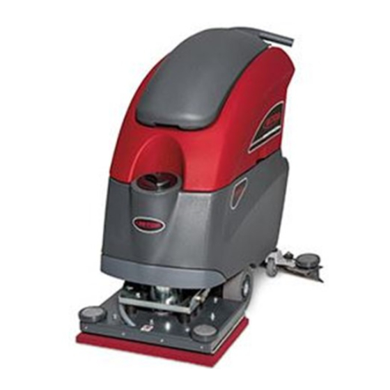
- Page 1 E89606-00 E89770-00 E89769-00 STEALTH ASO20BT 20” Automatic Scrubber ™ with Traction Drive Operator and Parts Manual 400 Van Camp Road • Bowling Green, Ohio 43402 Customer Service: 888-GO-BETCO • Fax: 800-445-5056 • Technical Service: 877-856-5954 • www.betco.com...
-
Page 2: Table Of Contents
RECEIVING THE MACHINE TABLE OF CONTENTS Immediately check, when receiving the machine, that all the materials indicated on delivery documents have been received and also that the machine has not been damaged in transit. If it has been damaged, this damage must be immediately reported to the shipper and also to our customer’s service department. -
Page 3: General Safety Regulations
Noise level 64 / 62 Eco Mode • When your BETCO machine is ready to be retired, the machine must be disposed of properly. It contains oils and electronic components. The machine was built using totally recyclable materials. • Use only pads furnished with the machine or those specified in the user's manual. Use of other pads can compromise safety. -
Page 4: Machine Preparation
Weight 68 lb. (31 kg) WARNING: Your charger must be set according to the type of bat- tery you install. Call BETCO customer service to ensure correct charger setting after replacement batteries are installed. E. Use a ramp to get the machine down from the pallet, pushing it backwards. -
Page 5: Machine Preparation
MACHINE PREPARATION MACHINE PREPARATION 9. CONNECTING THE BATTERY CONNECTOR 5. BATTERY MAINTENANCE Connect the battery connector (2) to the machine connector (1) For maintenance and recharging, follow the instructions provided by the battery manufacturer. 6. BATTERY DISPOSAL When the battery reaches the end of its working life, it must be disconnected by certified professional, and removed from the battery compartment. - Page 6 MACHINE PREPARATION MACHINE PREPARATION 11. INSTRUMENT PANEL COMPONENTS 14. ASSEMBLING THE SQUEEGEE The instrument panel components are identified as follows: For packaging reasons, the squeegee is supplied dismounted from the machine, 1. Levers to activate pad / traction (located beneath the handlebar) and must be assembled as follows: 2.
- Page 7 MACHINE PREPARATION MACHINE PREPARATION 16. ADJUSTING THE SQUEEGEE INCLINATION 20. PAD INSTALLATION During operation, the rear squeegee blade is slightly tilted backwards (by about A. Raise the deck and remove any pad or debris from the pad locking face. 0.2 in. (5 mm) in a uniform way over entire length. If it is necessary to increase B.
-
Page 8: Operation
OPERATION OPERATION 1. MACHINE OPERATION 2. REVERSE MOVEMENT A. Connect the battery plug to the machine plug. To move the machine in reverse push the switch levers (1) forward. WARNING: When moving the machine in reverse, raise the squeegee. 3. OVERFLOW DEVICE The machine has a float in a filter basket that trips when the recovery tank is B. -
Page 9: Shutting Down The Machine
SHUTTING DOWN THE MACHINE DAILY MAINTENANCE 1. END OF WORK 1. CLEANING THE RECOVERY TANK When shutting down the machine and before you perform any type of mainte- A. Raise the vacuum cover (1). nance: B. Remove the drain hose (2) from it's hook and empty the tank. A. -
Page 10: Daily Maintenance
DAILY MAINTENANCE WEEKLY MAINTENANCE 3. CLEANING THE SQUEEGEE 1. CLEANING THE SQUEEGEE HOSE To clean: Every week, or whenever vacuum seems to be unsatisfactory, check the squee- A. Take the machine to a safe location on flat ground and ensure that the device is in a safe condition. gee hose for obstructions. -
Page 11: Troubleshooting Guide
TROUBLESHOOTING GUIDE MAINTENANCE SCHEDULE RECOMMENDED SERVICE Stealth ASDO20B INSUFFICIENT WATER ON THE PAD INTERVALS (HOURS) 1. Check water level in solution tank (1). 100 200 400 DAILY 2. Check that the solution control valve (2) is rotated to the left. BATTERIES 3. -
Page 12: Wear Items Listing
WEAR ITEMS LISTING Wear Items Part # Description Part # Description E20060 Pad Driver E22637 Squeegee Blade Kit, 31" E20213 Isolator (10 per machine) E84277 Squeegee Blade Kit, Poly, 31" E22128 Bearing E84278 Squeegee Blade Kit, Latex, 31" E20215 Eccentric E11767 Battery 12V 130AH Wet E89831... - Page 13 ORBITAL DECK DRIVE DIAGRAM ORBITAL DECK DRIVE PARTS LISTING Item# Part # Description Qty. Item# Part # Description Qty. E20001 Spacer, 22 x 17 x 13 E20323 Washer, Lock, M6, SS E20048 Pipe E81046 Washer, Lock, M8 x 14.8 x 2, Zinc E20060 Pad Driver E84264...
- Page 14 SQUEEGEE ASSEMBLY DIAGRAM SQUEEGEE ASSEMBLY PARTS LISTING Item# Part # Description Qty. Item# Part # Description Qty. E84336 Mounting Stud E22352 Center Front Squeegee Blade Clamp E22637 Squeegee Blade Kit, 31" E22635 Clamp, Front Squeegee Blade E84277 Squeegee Blade Kit, Poly, 31" E22355 Center Rear Squeegee Blade Clamp E84278...
- Page 15 SQUEEGEE YOKE DIAGRAM SQUEEGEE YOKE PARTS LISTING Item# Part # Description Qty. Item# Part # Description Qty. E20006 Bushing E83824 Square Nut, M8 SS E88279 Micro Switch Sealed E81673 Nut, Hex Nyloc, M3 Zinc E20408 Squeegee Lift Lever E81342 Nut, Hex Jam, Nyloc, M8 SS E84339 Sheath E20119...
- Page 16 MAIN FRAME DIAGRAM MAIN FRAME PARTS LISTING Item# Part # Description Qty. Item# Part # Description Qty. E88253 Bushing E20108 Screw, Pan Hd Phil Self Tap M4.8x16 SS E20006 Bushing E20246 Flat Hd Soc Machine Screw M6x50 Zinc E83597 Brush Deck Lift Idler Arm Weldment E22002 Screw, M8 x 30 E20370...
- Page 17 TRANSAXLE DIAGRAM TRANSAXLE PARTS LISTING Item# Part # Description Qty. Item# Part # Description Qty. E88253 Bushing E20108 Screw, Pan Hd Phil Self Tap M4.8x16 SS E20006 Bushing E20246 Flat Hd Soc Machine Screw M6x50 Zinc E83597 Brush Deck Lift Idler Arm Weldment E22002 Screw, M8 x 30 E20370...
- Page 18 SOLUTION TANK DIAGRAM SOLUTION TANK PARTS LISTING Item# Part # Description Qty. Item# Part # Description Qty. E20285 Solution Tank ASM 1.18 E20577 Spacer E88258 Hose, Glass Reinforced 15 OD x 10 ID x 496 L 1.19 E20602 Fitting, Barbed Threaded E20409 Foot Pedal Latch Plate E20411...
- Page 19 RECOVERY TANK DIAGRAM RECOVERY TANK PARTS LISTING Item# Part # Description Qty. Item# Part # Description Qty. E88499 Hose, Vacuum 3.11.2 E20188 Hinge Pin E20074 Hinge Pin E83833 Hex Bolt M8x25 Zinc E20354 Recovery Tank ASM E82638 Screw, Pan Hd Phil Self Tap M3.9x13 SS E20189 Fitting, Barbed E82808...
- Page 20 VACUUM UNIT DIAGRAM VACUUM UNIT PARTS LISTING Item# Part # Description Qty. Item# Part # Description Qty. E20265 Plate 2.19 E20064 Support Bracket E20066 Recovery Tank Cover ASM 2.20 E88291 Vacuum Motor 24VDC 310W E20305 Mounting Ring 2.20.1 E83897 Connector, Electrical Housing 30A 2.19 2.27 E20652...
- Page 21 SOLUTION DELIVERY DIAGRAM SOLUTION DELIVERY PARTS LISTING Item# Part # Description Qty. Item# Part # Description Qty. E81035 Solenoid Valve E20602 Fitting, Threaded Barb E85762 Hose Clamp E22145 Fitting, 3/8" - 1/4" Reducer E22144 Tubing, 10 ID x 370 L E88829 Fitting, 90 Degree Elbow E20375...
- Page 22 HANDLEBAR DIAGRAM HANDLEBAR PARTS LISTING Item# Part # Description Qty. Item# Part # Description Qty. E20330 Ball Stud M10x22.5 1.25 E20362 Set Screw Hex Soc Dog Point M5x30 Zinc E20574 Bushing 1.26 E20298 Soc Button Head Screw M5x16 SS 1.47 1.37 1.14 E82351...
- Page 23 ELECTRICAL DIAGRAM ELECTRICAL PARTS LISTING Item# Part # Description Qty. Item# Part # Description Qty. Various Batteries E20713 Potentiometer Various Battery Charger Dilution Control Commutator Card (Not Used) Fuse Dilution Control Card (Not Used) E83316 Key Switch E81035 Solenoid Valve E84353 Battery Discharge Indicator E84351...
-
Page 24: Battery Check Card - Hour Meter
BATTERY CHECK CARD / HOUR METER SOLUTION TANK INSPECTIONS 1. Verify that when turning on the machine, the battery discharge indicator has the following starting sequence: 1. Fill up the solution tank and verify the sealing of the gasket particularly •... -
Page 25: Brake Adjustment
BRAKE ADJUSTMENT CHECK LIST Functional check of the machine Check the functionality of switches. 1. Verify that the brake on the left hand wheel locks the wheel when active. 2. Otherwise adjust as follows: Check the functionality of the switch lever. •... -
Page 27: Warranty
Service Distributor. If the original part is returned within the warranty policy period from date of delivery for inspection by Betco and is found to be defective the owner will be credited for the cost of replacement parts plus shipping and handling.
Need help?
Do you have a question about the STEALTH ASO20BT and is the answer not in the manual?
Questions and answers