Table of Contents
Advertisement
Advertisement
Table of Contents

Related Manuals for BETCO STEALTH DRS21BT


Summary of Contents for BETCO STEALTH DRS21BT
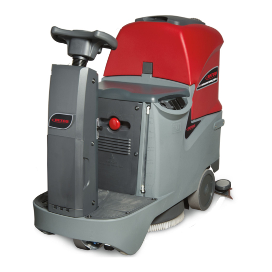
- Page 1 E29961-00 E29963-00 E29962-00 STEALTH DRS21BT 21” MicroRider ™ Automatic Scrubber Parts and Maintenance Catalog 1001 Brown Avenue • Toledo, Ohio 43607-0127 Customer Service: 888-GO-BETCO • Fax: 800-445-5056 • Technical Service: 877-856-5954 • www.betco.com...
-
Page 2: Table Of Contents
TABLE OF CONTENTS INTRODUCTION ............. 3 DIAGRAMS AND PARTS LISTINGS ......4 - 31 STEERING WHEEL FUNCTION ......32 - 40 ELECTRIC INSTALLATION TEST......41 - 45 PLUMBING INSTALLATION CHECKS ......46 TRACTION, STEERING, & BRAKE ADJUSTMENT..47 - 48 VACUUM ADJUSTMENT ........48 - 49 BRUSH DECK ADJUSTMENT ........ -
Page 3: Introduction
INTRODUCTION This catalog is intended to serve as a guide for the ordering of spare parts and is designed to facilitate the rapid identification and location of parts. To simplify ordering and delivery of spare parts, the following information should be provided when plac- ing an order: 1. - Page 4 BRUSH DECK ASSEMBLY DIAGRAM 4.2.1...
-
Page 5: Table Of Contents
BRUSH DECK ASSEMBLY PARTS LISTING Item# Part # Description Item# Part # Description E86164 Flat Washer M9x24x2.5 SS E22638 Spring E22206 Tubing, PVC, M20 OD x M13 ID x 220 LG E20253 Flat Washer M21x60x3 Nylon E22639 Tubing, 1.25" E83529 Carbon Motor Brush E88245 Motor, Geared 24V 400W 140 RPM... - Page 6 SQUEEGEE ASSEMBLY - STANDARD 28" DIAGRAM...
- Page 7 SQUEEGEE ASSEMBLY - STANDARD 28" PARTS LISTING Item# Part # Description Item# Part # Description E22255 Stud Bolt E22346 Screw, Custom Cap E22659 Squeegee Blade Kit, 28" E22663 Squeegee Body, 28" E22352 Center Front Squeegee Blade Clamp E22659 Squeegee Blade Kit, 28" E22660 Squeegee Blade Kit Poly, 28"...
- Page 8 SQUEEGEE ASSEMBLY - OPTIONAL 31.5" DIAGRAM 31.5...
- Page 9 SQUEEGEE ASSEMBLY - OPTIONAL 31.5" PARTS LISTING Item# Part # Description Item# Part # Description E22346 Screw, Custom Cap E22255 Stud Bolt E22637 Squeegee Blade Kit, 31" E22633 Squeegee Body E22637 Squeegee Blade Kit, 31" E22352 Center Front Squeegee Blade Clamp E84277 Squeegee Blade Kit Poly, 31"...
- Page 10 SQUEEGEE SUPPORT ASSEMBLY DIAGRAM...
- Page 11 SQUEEGEE SUPPORT ASSEMBLY PARTS LISTING Item# Part # Description Item# Part # Description E22670 Lift Chain E83799 Flat Washer M6.6x18x2 SS E22282 Bushing M12 OD x 6.25 ID x 30.5 LG E22672 Nut, M6, 18mm Height E82314 Nyloc Hex Nut, M6 SS E82772 Hex Bolt M6x20 Zinc E22671...
- Page 12 CHASSIS ASSEMBLY DIAGRAM...
-
Page 13: Clamp, 4.8X200 Black
CHASSIS ASSEMBLY PARTS LISTING Item# Part # Description Item# Part # Description E82761 Flat Washer M6x12x1.6 Zinc E22584 Spacer E22678 Bushing E83278 Flat Washer M6.5x24x2 Zinc E20609 Bearing Mount Base E82774 Lock Washer, M6 Zinc E20014 Bearing Mount Cap E81874 Flat Washer M8x17x1.6 Zinc E88279 Micro Switch Sealed... - Page 14 STEERING COLUMN ASSEMBLY DIAGRAM 1.2.2 1.2.1 5.17 5.12 5.19 5.11 5.16 5.12 5.19 5.17 5.11 5.16 5.13 5.10 5.14 5.11 5.18 5.16 5.15 5.15 5.11 5.16 5.13 5.10 5.14...
- Page 15 STEERING COLUMN ASSEMBLY PARTS LISTING Item# Part # Description Item# Part # Description E81917 Bolt, Hex, M8x20, Zinc E82351 Key Switch Assembly w/Keys E83173 Contact, Key Switch E83833 Hex Bolt M8x25 Zinc 1.2.1 E83316 Key Switch E22185 1.2.2 E83315 Switch Key (1) E83852 Hex Nut, M6x5 E81358...
- Page 16 STEERING WHEEL ASSEMBLY DIAGRAM...
- Page 17 STEERING WHEEL ASSEMBLY PARTS LISTING Item# Part # Description Item# Part # Description E20293 Flat Washer M4x10x1 Nylon E84221 Reverse Button Cover E83935 Wire Tie E84222 ECO Mode Button Cover E84223 Steering Wheel Shaft E81565 Clamp, 4.8x200 Black E84217 Screw, M5 x 16 E84224 Control Card E81875...
- Page 18 FRONT WHEEL ASSEMBLY DIAGRAM...
- Page 19 FRONT WHEEL ASSEMBLY PARTS LISTING Item# Part # Description Item# Part # Description E84229 Wheel Mount E86216 Spacer E81915 Flat Washer M8.2x32x4 Zinc E84230 Cam Plate E88020 Bearing E84231 Steering Gear E20096 Hex Bolt M8x25 SS E84232 Bearing Support E22681 Screw, M6 x 30 E84233 Axle Shaft...
- Page 20 EXTERIOR COMPONENTS DIAGRAM...
- Page 21 EXTERIOR COMPONENTS PARTS LISTING Item# Part # Description Item# Part # Description E84235 Recovery Lid Gasket E20121 Flat Washer M5x15x1.5 Zinc E83850 Flat Washer M5x20 SS E83404 Flat Washer M9x24x2.5 Zinc E83704 Lock Washer M8x13x2.2 Zinc E22381 Screw, Pan Hd Phil Self Tap M4.2x16 SS E84236 Recovery Tank Lid E83165...
- Page 22 SOLUTION TANK ASSEMBLY DIAGRAM...
- Page 23 SOLUTION TANK ASSEMBLY PARTS LISTING Item# Part # Description Item# Part # Description E81786 Hose Clip E84317 Sight Tube E84280 Bushing E88717 Grommet, Push-In, M13 x M8 E83839 Oval Hd Phil Machine Screw M5x16 Zinc E22328 Fitting, Barbed Elbow E22292 Pan Hd Phil Machine Screw M5x16 Zinc E22381 Screw, Pan Hd Phil Self Tap M4.2x16 SS...
- Page 24 RECOVERY TANK ASSEMBLY DIAGRAM 5.1.1...
- Page 25 RECOVERY TANK ASSEMBLY PARTS LISTING Item# Part # Description Item# Part # Description E81565 Clamp, 4.8x200 Black E82838 Motor Plaque E22225 Connecting Rod M5 x 102 LG Zinc E81786 Hose Clip E84286 Hook Assembly E20382 Nyloc Hex Nut, M5 x 5 Zinc E84287 Tubing E20613...
- Page 26 WATER DISTRIBUTION ASSEMBLY DIAGRAM...
- Page 27 WATER DISTRIBUTION ASSEMBLY PARTS LISTING Item# Part # Description Item# Part # Description E84257 Tubing 12 ID x 350 L E84260 Hose Clamp E20328 Tubing 12 ID x 480 L E85762 Hose Clamp E82366 Valve E88207 Filter Assembly, Inline Double Female 1/2" NPT E20512 Filter, Body E81454...
- Page 28 ELECTRICAL COMPONENTS DIAGRAM...
- Page 29 ELECTRICAL COMPONENTS PARTS LISTING Item# Part # Description Item# Part # Description E84629 Washer E84268 Wire Loom Protection E83850 Flat Washer M5x20 SS E84270 Cover E83839 Oval Hd Phil Machine Screw M5x16 Zinc E84271 Emergency Stop E2039200 Pan Hd Phil Machine Screw M4x16 Zinc E84272 Mounting Plate E20121...
- Page 30 OPTIONAL SPLASH SKIRT ASSEMBLY DIAGRAM...
- Page 31 OPTIONAL SPLASH SKIRT ASSEMBLY PARTS LISTING Item# Part # Description Item# Part # Description E84275 Splash Guard E83489 Rings E83491 Spring, 9.8x1.1x58mm Zinc Extension E84275 Splash Guard E20341 Hex Bolt M4x16 Zinc E84276 Retaining Blade E20248 Hex Nut, M4x4 Zinc E84276 Retaining Blade...
- Page 32 STEERING WHEEL FUNCTION THE STEERING WHEEL CONSOLE ALLOWS THE FOLLOWING FUNCTIONS: 1. Setup and manage the main functions and commands of the machine during operation. 2. Access to the following program menus: A: USER MENU - This menu provides access to all the base functions of the machine, intended for operators. B: ADVANCED MENU - This menu provides access to detailed functionality of the machine and electric monitoring systems.
- Page 33 Check connections to the vacuum limit switch in Vacuum limit switch fault Act2:endsw fail the steering column. AL_8: Function Brush actuator: final position Not used on the Stealth DRS21BT Act1:timeout not reached AL_9: Function Vacuum actuator: final Not used on the Stealth DRS21BT...
- Page 34 STEERING WHEEL FUNCTION USING AND ACCESSING MENUS: The steering wheel also acts as a programming and troubleshooting console. Using a specific key sequence, it is possible to access two types of menus. 1. USER MENU - This menu provides access to all the base functions of the machine, intended for operators. 2.
- Page 35 STEERING WHEEL FUNCTION USER MENU Menu Default Available Values Description General Setup: Language: IT - EN - DE - FR - SP Language Setup # # # General Setup: Model: # # Machine Model Setup (DO NOT MXR - MXR FSS CHANGE) General Setup: Battery: # GEL - WET - AGM -...
-
Page 36: Steering Wheel Function
Access to "User Menu" sets. Options menu: >Brushes Access to parameters related to the brush sets. motor Options menu: >Pumps Not used on Stealth DRS21BT sets. Options menu: >Vacuum Access to parameters related to the vacuum sets. motor Options menu: >Traction Access to parameters related to the traction sets. - Page 37 STEERING WHEEL FUNCTION ADVANCED MENU "GENERAL SETTINGS" The "General Settings" submenu allows access to general parameters. This is very similar to the "User Menu". Menu Default Available Values Description General Sets: Language: # IT - EN - DE - FR - SP Language Setup General Sets: Model: # # Machine Model Setup MXR - MXR FSS...
- Page 38 STEERING WHEEL FUNCTION ADVANCED MENU "BRUSH SETTINGS" The "Brush Settings" submenu allows access to enter parameters and settings related to the brush motor. Menu Default Description Brushes Sets: I_Max: Maximum current sent from the control card to the # # [Amp] brush motor Nominal current defines the amp draw at which the Brushes Sets:...
- Page 39 STEERING WHEEL FUNCTION ADVANCED MENU "TRACTION SETTINGS" The "Traction Settings" submenu allows access to enter parameters and settings related to the traction drive motor. Menu Default Description Traction Sets: Acceleration ramp, the time needed to reach maximum Acc_Ramp: # . # [Secs] speed.
- Page 40 STEERING WHEEL FUNCTION ADVANCED MENU "CHECK & MONITOR" The "Check/Monitor" submenu show the condition of the machine while in use. This is very helpful for troubleshooting pur- poses. Menu Display Description Check/Monitor: I_Tr: # # Current amp draw of the traction motor. [Amp] Check/Monitor: I_Br: # # Current amp draw of the brush motor.
- Page 41 ELECTRIC INSTALLATION TEST ELECTRIC INSTALLATION TESTING 1. Check the functionality of the electric installation: switches, contactors, mo- tors, solenoid valve, power fuses, thermal switches, and emergency button. Remove the bottom plate and the front cover where the emergency stop is located to gain access to the electric installation.
- Page 42 ELECTRIC INSTALLATION TEST 2.2. To adjust the potentiometer: • Remove the foot rest plate • To remove the pedal, remove the two screws holding it in place and discon- nect the wiring plug. • Remove the plastic cap • Loosen the dowel set screw...
- Page 43 ELECTRIC INSTALLATION TEST • Rotate the small shaft of the pedal clockwise until it reaches its end (zero) position. • Use a meter to check the resistance value. Place the testing probes on the yellow and red cables to verify that the resistance is near to zero ohm. •...
- Page 44 ELECTRIC INSTALLATION TEST 3. Check the functionality and connections of the brush enable microswitch, vacuum enable microswitch, and backward enable microswitch. When the microswitch is activated, there should be 0.5 mm of clearance between the lever and the body of the switch. Check that the lever of the switch operates correctly.
-
Page 45: Electric Installation Test
ELECTRIC INSTALLATION TEST 4. Check the functionality and connection of the speed reduction microswitch placed near the steering gear of the front wheel. When the microswitch is activated, there should be 0.5 mm of clearance between the lever and the body of the switch. Check that the lever of the switch operates correctly. -
Page 46: Plumbing Installation Checks
PLUMBING INSTALLATION CHECKS 1. Check the cleanliness and functionality of the solution fill hose and the solu- tion cap measuring cup. 2. Check the cleanliness and seal of the solution filter. 3. Fill up the solution tank. 4. Check the hose connections for leaking, check the solenoid valve for proper operation, and check the solution flow control valve. -
Page 47: Traction, Steering, & Brake Adjustment
TRACTION, STEERING, & BRAKE ADJUSTMENT 1. Check the functionality of the electronic brake • With the brake lever in a down position (electronic brake ON), the machine will not move when pushed or parked on an incline. • With the brake lever in an up position (electronic brake OFF), the machine will roll freely when pushed. - Page 48 TRACTION, STEERING, & BRAKE ADJUSTMENT / VACUUM ADJUSTMENT • Loosen the nuts that hold the bearing plate to the frame. • To adjust the tension, use the nuts and register dowels to move the bearing plate forward or backward. • Once the chain has proper tension, tighten the nuts that hold the bearing plate to the frame.
-
Page 49: Vacuum Adjustment
VACUUM ADJUSTMENT 4. Check the connections of the vacuum hose to the recovery tank and the squeegee assembly. -
Page 50: Brush Deck Adjustment
BRUSH DECK ADJUSTMENT 1. The brush deck is on a floating support, it is only necessary to adjust the hori- zontal incline. 2. To adjust the horizontal incline: • Loosen the bottom two bolts that connect the brush deck to the lift arm. •... -
Page 51: Squeegee Adjustment
SQUEEGEE ADJUSTMENT 1. Adjust the wheel height by loosening the bolt through the middle of the wheel and placing a 2 mm spacer between the wheel and the floor. This measure- ment should be taken with the squeegee lowered and the squeegee blades in a vertical position. -
Page 52: Warranty
Service Distributor. If the original part is returned within the warranty policy period from date of delivery for inspection by Betco and is found to be defective the owner will be credited for the cost of replacement parts plus shipping and handling.
Need help?
Do you have a question about the STEALTH DRS21BT and is the answer not in the manual?
Questions and answers