
Subscribe to Our Youtube Channel
Related Manuals for OLIMEX ADuC-IO7020


Summary of Contents for OLIMEX ADuC-IO7020
- Page 1 ADuC-IO7020 development board Users Manual All boards produced by Olimex are ROHS compliant Rev. A, September 2005 Copyright(c) 2009, OLIMEX Ltd, All rights reserved Page 1...
-
Page 2: Board Features
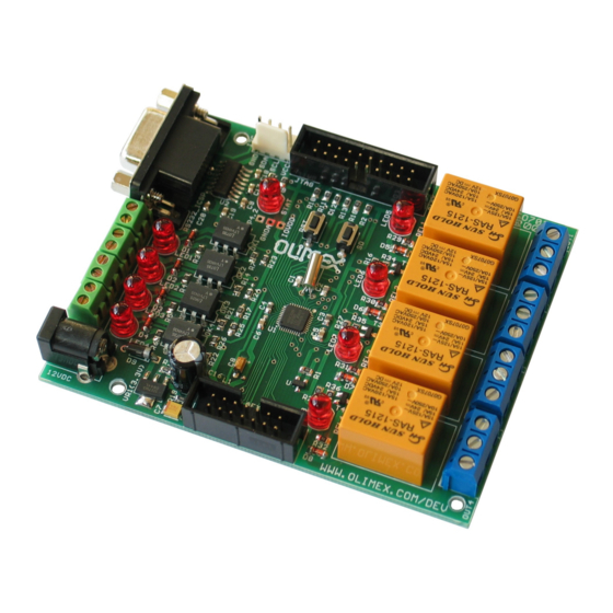
INTRODUCTION ADuC-IO7020 is very good platform for automation application which need fast ADC and DACs and need to commutate high loads. It have 4 relays 240VAC/10A, 4 optoisolated inputs, RS232, JTAG and the 1Msps ADC/DACs are available on separate conenctor for connection to external sensors. -
Page 3: Electrostatic Warning
ELECTROSTATIC WARNING The ADuC-IO7020 board is shipped in protective anti-static packaging. The board must not be subject to high electrostatic potentials. General practice for working with static sensitive devices should be applied when working with this board. BOARD USE REQUIREMENTS Depends on the used programming/debugging tool. -
Page 4: Block Diagram
2 X General Purpose Timers – Wake-up and Watchdog Timers – Power Supply Monitor – PLA – Programmable Logic (Array) – Power – Specified for 3V operation – Active Mode: 6mW (@1MHz) – 300mW (@45MHz) BLOCK DIAGRAM Page 4... -
Page 5: Memory Map
MEMORY MAP Page 5... - Page 6 SCHEMATIC P1.2 P0.4 S CL P1.1 RX D P1.0 P0.3 T X D P0.3/T RST P4.2 DGND 470nF VREF LVDD VREF LVDD AGND IOVDD V CC AVDD IOGND 100nF AVDD ADC0 ADC0 T DO ADC1 ADC1 T CK ADC2 P0.6 ADC2 Page 6...
-
Page 7: Board Layout
The board power consumption at first, without Relays is: about 40 mA, when all Relays are working the consumption is 180 mA. RESET CIRCUIT ADuC-IO7020 reset circuit is includes R1 (1k) pull-up, U4 (MCP130T), ADuC7020 pin 19 and RST button. CLOCK CIRCUIT Quartz crystal 32.768 KHz is connected to ADuC7020 pin 24 (XCLKO) and pin 25... -
Page 8: External Connectors Description
INPUT/OUTPUT Status LED (red) with name STAT connected to AduC7020 pin 22 (P2.0) Status LED (red) with name LED1 - indicates that OK1 is working Status LED (red) with name LED2 - indicate that OK2 is working Status LED (red) with name LED3 - indicate that OK3 is working Status LED (red) with name LED4 - indicate that OK4 is working Status LED (red) with name LED5 - indicate that REL1 is working Status LED (red) with name LED6 - indicate that REL2 is working... - Page 9 Pin # Signal Name Power Input AEXT Pin # Signal Name Pin # Signal Name AVDD AVDD ADC0 DAC0 ADC1 DAC1 ADC2 DAC2 ADC3 DAC3 ADC4 VREF Page 9...
- Page 10 RS232_ICSP Pin # Signal Name Not connected T1_OUT R1_IN Not Connected Not Connected Not Connected Not Connected Not Connected Pin # Signal Name +3.3 V IN1, IN2, IN3, IN4 Pin # Signal Name Optoisolated Digital Input 1 Optoisolated Digital Input 2 OUT1, OUT2, OUT3, OUT4 Pin # Signal Name...
-
Page 11: Mechanical Dimensions
MECHANICAL DIMENSIONS All measures are in Inches. Page 11... -
Page 12: Available Demo Software
AVAILABLE DEMO SOFTWARE ADC read DAC write demo code for EW-ARM Blink LED demo code for EW-ARM RS232 , UART, demo code for EW-ARM DAC sinusoidal generation demo code for EW-ARM SPI demo code for EW-ARM Basic initializations for ADUC7020 demo code for EW-ARM Page 12... -
Page 13: Order Code
ORDER CODE ADuC-IO7020 - completely assembled and tested. How to order? You can order to us directly or by any of our distributors. Check our web www.olimex.com/dev for more info. Revision history: REV. A - create September 2005 Page 13... - Page 14 This document is intended only to assist the reader in the use of the product. OLIMEX Ltd. shall not be liable for any loss or damage arising from the use of any information in this document or any error or omission in such information or any incorrect use of the product.
Need help?
Do you have a question about the ADuC-IO7020 and is the answer not in the manual?
Questions and answers