
Related Manuals for OLIMEX A20-SOM


Summary of Contents for OLIMEX A20-SOM
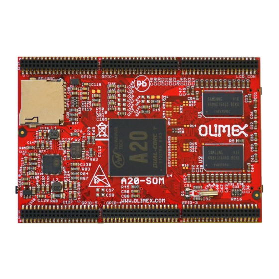
- Page 1 A20-SOM AND A20-SOM-4GB System-on-Module boards capable of Linux and Android boot USER’S MANUAL Document revision I, March 2015 Designed by OLIMEX Ltd, 2015 All boards produced by Olimex LTD are ROHS compliant...
-
Page 2: Disclaimer
This document is intended only to assist the reader in the use of the product. OLIMEX Ltd. shall not be liable for any loss or damage arising from the use of any information in this document or any error or omission in such information or any incorrect use of the product. -
Page 3: Table Of Contents
1.4 Board variants .......................... 7 1.5 Board versions used in the manual ..................7 1.6 Document organization ......................7 CHAPTER 2: SETTING UP THE A20-SOM BOARD ........... 8 2. Introduction to the chapter ....................... 8 2.1 Electrostatic and electrical polarity warnings ............... 8 2.2 Requirements ........................... - Page 4 OLIMEX© 2015 A20-SOM user's manual 6.2 UART0 pins ..........................22 6.3 MicroSD card connector ....................... 23 6.3.1 SD/MMC slot ..............................23 6.4 Power pins for external power supply .................. 24 6.5 GPIO connectors ........................24 6.5.1 GPIO-1 (General Purpose Input/Output) 40pin connector ..............25 6.5.2 GPIO-2 (General Purpose Input/Output) 40pin connector ..............
-
Page 5: Chapter 1: Overview
Thank you for choosing this single board computer from Olimex! This document provides a user’s guide for the A20-SOM board. As an overview, this chapter gives the scope of this document and lists the board’s features. The document’s organization is then detailed. -
Page 6: Target Market Of The Board
A20-SOM user's manual 1.2 Target market of the board Using the A20-SOM as a stand-alone development board would be more suitable for users with some hardware experience or people already familiar with other single-board Linux boards and designs. As mentioned in the previous chapter the board is meant to be implemented in a hardware design. -
Page 7: Board Variants
NAND memory that allows the storage of an operating system without the need of a SD card (at the moment of writing this document Olimex provides only Android OS for the NAND). The 4GB version comes with already programmed and ready-to-use Android OS image. -
Page 8: Chapter 2: Setting Up The A20-Som Board
2.2 Requirements In order to set up the A20-SOM board optimally one or more additional items may be needed. They might be generally placed in two categories: Required – items that are needed in order to achieve minimum functionality;... -
Page 9: Powering The Board
2.3.1 Stand-alone powering If you use the board in stand-alone mode (e.g. it is neither attached to A20-SOM-EVB nor to any other board of peripherals) there are fewer options for powering it. Consider that you might need additional cables or connectors. You have the following options of powering the board: 1. -
Page 10: Mounted Powering
40-pin headers. A20-SOM receives power from A20-SOM-EVB, but what are the requirements to power A20-SOM-EVB? You need to provide 6V to 16V DC voltage to the power jack (named PWR) of A20-SOM-EVB board. The DC barrel jack has 2.0mm inner pin and 6.3mm hole. More information about the exact component might be found here: https://www.olimex.com/wiki/PWRJACK... -
Page 11: Interacting With The Board
A20-SOM user's manual 2.5 Interacting with the board The typical and recommended way of interacting with A20-SOM board is via a serial cable connected between the UART-DEBUG header and a personal computer. You would probably need a cable suitable for such a connection due to the fact that most personal computers lack a serial port nowadays. -
Page 12: Expanding The Debian File System Space
Download locations to such images might be found at the wiki article for the A20 board here: https://www.olimex.com/wiki/A20-SOM. For Linux Debian you would need to execute a shell script to be able to change the resolution. It is... - Page 13 OLIMEX© 2015 A20-SOM user's manual Then the main menu of the video configuration script shows up: Choose the resolution and the interface (LCD, HDMI or VGA). The supported resolutions are listed on the next page. For LCD: 1. 4.3" (480×272) 2.
- Page 14 7. 1920×1080 8. 1280×720 Depending on the display or the screen you want to use with the A20-SOM, you might need to apply software changes to the prebuilt Android or Linux image. The easiest way would be to do it on the board itself but it can be done offline too (manipulating the image located on the microSD card via a microSD card reader).
-
Page 15: Connecting And Calibrating A Display
However, there is only a 40-pin female connector LCD_CON with a 0.05'' step. Unlike other OLIMEX Allwinner boards, the A20-SOM lacks a row of pins that allows the user to connect a display out-of-the-box. The board's LCD_CON connector is female and has a smaller 0.05'' step. -
Page 16: Android Calibration
If the problem is under Debian Linux make sure you are properly logged in the LXDE interface! Else applying calibration would not happen for the current user – if you are calibrating from the X graphical interface make sure that you are logged as user “olimex” (if calibrating without the X, the user is “root”). -
Page 17: Software Support
We usually try to provide details on how to build the Linux and the Android images at our wordpress page: http://olimex.wordpress.com/. Another useful place is the Olimex forums where a lot of people share their experience and advice: https://www.olimex.com/forum/. The official images are a constant work-in-progress – newer releases are packed with better hardware support, newer kernels and extra features. -
Page 18: Chapter 3: Board Description
3. Introduction to the chapter Here you get acquainted with the main parts of the board. Note the names used on the board might differ from the names used below to describe them. For the actual names check the A20-SOM board itself. -
Page 19: Chapter 4: The Allwinner A20 Microcontroller
CHAPTER 4: THE ALLWINNER A20 MICROCONTROLLER 4. Introduction to the chapter In this chapter is located the information about the heart of A20-SOM – its microcontroller. The information is a modified version of the datasheet provided by its manufacturers. 4.1 The processor The main feature of the A20 processor is the sheer computing power that allows FullHD video playback. -
Page 20: Block Diagram
OLIMEX© 2015 A20-SOM user's manual AUDIO Integrated HI-FI 100dB Audio Codec Dual analog mic amplifiers More information can be found on Allwinner's web site at the following web-address: http://www.allwinnertech.com/en/clq/processora/A20.html 4.2 Block diagram The block diagram is taken from Allwinner's web-site. -
Page 21: Chapter 5: Control Circuity
(if you have provided over voltage and want to repair the board yourself). A20-SOM typically consumes between 0.20A and 0.25A when connected to a 5V voltage source (provided at pins GND and 5VEXT). During heavy load of the processor the consumption might raise up to 0.35A (tested with 'top d0'). -
Page 22: Chapter 6: Connectors And Pinout
Note that by default only UART0 is defined as a port suitable for serial debug. You can use our USB-SERIAL-CABLE-F for debugging. Even when A20-SOM is mounted on A20-SOM-EVB the default debug port remains UART0 (despite that it gets additional pins on the big board also for easier access). -
Page 23: Microsd Card Connector
When in doubt – try the same operation with another card from another brand. Olimex sells microSD cards with Linux or Android images, that have been tested – please refer to chapter “2.2 Requirements”. Of course, if you already have a large enough microSD card you can download the official Linux image from the wiki pages: https://www.olimex.com/wiki/A20-SOM. -
Page 24: Power Pins For External Power Supply
More info about the power supply can be found in chapter 5 of this manual. 6.5 GPIO connectors There are 6 GPIO connectors located on the top side of A20-SOM. They ease the access to processors pins. These connectors (except for GPIO-6) also provide a way to mount the board to a board with peripherals. -
Page 25: Gpio-1 (General Purpose Input/Output) 40Pin Connector
OLIMEX© 2015 A20-SOM user's manual OLIMEX sells additional and replacement male and female 0.05'' (50 mil) step connectors. We also have a suitable cable named CABLE-40-40-10CM. The only power line at the GPIO connectors that might be used as input is the one named '5VEXT'. -
Page 26: Gpio-2 (General Purpose Input/Output) 40Pin Connector
OLIMEX© 2015 A20-SOM user's manual 6.5.2 GPIO-2 (General Purpose Input/Output) 40pin connector GPIO-2 connector Pin # Signal name Processor pin# Pin # Signal name Processor pin# 1 5VEXT -POWER CIRCUIT- 2 GND -POWER CIRCUIT- 3 BAT -POWER CIRCUIT- 4 GND... -
Page 27: Gpio-3 (General Purpose Input/Output) 40Pin Connector
OLIMEX© 2015 A20-SOM user's manual 6.5.3 GPIO-3 (General Purpose Input/Output) 40pin connector GPIO-3 connector Pin # Signal name Processor pin# Pin # Signal name Processor pin# 1 +5V -POWER CIRCUIT- 2 GND -POWER CIRCUIT- 3 3.3V -POWER CIRCUIT- 4 GND... -
Page 28: Gpio-4 (General Purpose Input/Output) 40Pin Connector
OLIMEX© 2015 A20-SOM user's manual 6.5.4 GPIO-4 (General Purpose Input/Output) 40pin connector GPIO-4 connector Pin # Signal name Processor pin# Pin # Signal name Processor pin# 1 5VEXT -POWER CIRCUIT- 2 GND -POWER CIRCUIT- 3 3.3V -POWER CIRCUIT- 4 LDO3_2.8V... -
Page 29: Gpio-5 (General Purpose Input/Output) 40Pin Connector
OLIMEX© 2015 A20-SOM user's manual 6.5.5 GPIO-5 (General Purpose Input/Output) 40pin connector GPIO-5 connector Pin # Signal name Processor pin# Pin # Signal name Processor pin# 1 PG0 2 GND -POWER CIRCUIT- 3 PG1 4 SDC3-D0 5 PG2 6 SDC3-D1... -
Page 30: Lcd_Con 40Pin Connector
The LCD_CON pins are led out on a separate 40pin connecter for the ease of connecting an LCD. The step of the connector of A20-SOM is still 0.5''. We have tested the ability of the board to interact with such a display. They allow the user to attach additional hardware, check readings or perform hardware debug. -
Page 31: Jumper Description
+5V and 5VEXT power lines. 6.8 Additional hardware components The components below are mounted on the A20-SOM but are not discussed above. They are listed here for completeness: Reset button – used to reset the board Power button –... -
Page 32: Chapter 7: Schematics
In this chapter is located information about the schematics describing logically and physically A20- SOM. 7.1 Eagle schematic A20-SOM schematics may be found it on the OLIMEX's GitHub repository: https://github.com/OLIMEX/SOM/tree/master/A20. You can download the whole repository as .zip without having a GitHub account. -
Page 33: Chapter 8: Revision History And Support
OLIMEX© 2015 A20-SOM user's manual CHAPTER 8: REVISION HISTORY AND SUPPORT 8. Introduction to the chapter In this chapter you will find the current and the previous version of the document you are reading. Also the web-page for your device is listed. Be sure to check it after a purchase for the latest available updates and examples. -
Page 34: Board Revision
OLIMEX© 2015 A20-SOM user's manual 8.2 Board revision Remember to check the schematics and the board design files to compare the differences. Board revision Notable changes Initial release of the board 1. Optimized values 2. Resolved various multiplexing issues 3. Renamed few wires properly 1. -
Page 35: Useful Web Links And Purchase Codes
SATA port, Headphones jack, Microphone jack, Camera, etc) USB-SERIAL-CABLE-F – USB serial console cable female A20-SOM-Android-SD – a tested class 10 micro SD card with the latest (by the time of leaving the Olimex facilities) official Android release A20-SOM-REV-D-DEBIAN-SD – a tested, class 10 micro SD card suitable for A20-SOM boards revision C or newer;... - Page 36 How to purchase? You can purchase directly from our online shop or from any of our distributors. Note that usually it might be faster and cheaper to purchase Olimex products from our distributors. List of confirmed Olimex LTD distributors and resellers: https://www.olimex.com/Distributors.
-
Page 37: Frequently Asked Questions
OLIMEX© 2015 A20-SOM user's manual 8.4 Frequently asked questions Q: I powered my board, it showed a logo and then nothing happened. What might be the problem? A: This might be due to a number of reasons but it is recommended to try the following: 1. - Page 38 Sunxi u-boot loader – the linux-sunxi git page contains a lot of sources for all Olimex Allwinner boards. Q: How to detect and enable the Ethernet controller (if it is disabled by default)? A: You can enable it by following these two steps: 1.
- Page 39 We recommend 4GB class 10 card. • Press and hold RECOVERY button, apply power supply (the requirement various depending on whether you use the board stand-alone or on top of A20-SOM-EVB), release RECOVERY button. • Connect USB cable to the mini USB connector.
- Page 40 4. Disconnect the power supply and USB cable from the A20 board. 5. Press and hold RECOVERY button, apply power supply (the requirement various depending on whether you use the board stand-alone or on top of A20-SOM-EVB), release RECOVERY button. 6. Connect USB cable to the mini USB connector.
-
Page 41: Product Support
All goods are checked before they are sent out. In the unlikely event that goods are faulty, they must be returned, to OLIMEX at the address listed on your order invoice. OLIMEX will not accept goods that have clearly been used more than the amount needed to evaluate their functionality.
Need help?
Do you have a question about the A20-SOM and is the answer not in the manual?
Questions and answers