Table of Contents
Advertisement
Quick Links
Advertisement
Table of Contents

Related Manuals for OLIMEX A13-OLinuXino


Summary of Contents for OLIMEX A13-OLinuXino
- Page 1 All manuals and user guides at all-guides.com A13-OLinuXino and A13-OLinuXino-WIFI Open-source single-board Android 4.0 mini-computer USER’S MANUAL Revision F, March 2013 Designed by OLIMEX Ltd, 2012 All boards produced by Olimex LTD are ROHS compliant Elcodis.com electronic components distributor...
-
Page 2: Disclaimer
This document is intended only to assist the reader in the use of the product. OLIMEX Ltd. shall not be liable for any loss or damage arising from the use of any information in this document or any error or omission in such information or any incorrect use of the product. -
Page 3: Table Of Contents
2.6.6. Applying the script and uploading the confing ..................13 2.6.7. Restarting the A13-OLinuXino ........................13 2.7 Configuration of hardware in the Debian image ..............13 CHAPTER 3: A13-OLINUXINO BOARD DESCRIPTION ......... 14 3. Introduction to the chapter ..................... 14 3.1 Layout (top view) ........................14 CHAPTER 4: THE ALLWINNER A13 MICROCONTROLLER ....... - Page 4 OLIMEX© 2012 A13-OLinuXino user's manual 6.1.2 UART1 interface ............................20 6.2 SD/MMC slot .......................... 21 6.3 UEXT module ......................... 22 6.4 GPIO-1 (General Purpose Input/Output) 10pin connector ..........23 6.5 GPIO-2 (General Purpose Input/Output) 40pin connector ..........23 6.6 LCD_CON 40pin connector ....................25 6.7 PWR Jack ..........................
-
Page 5: Chapter 1: Overview
Thank you for choosing the OLinuXino single board computer from Olimex! This document provides a user’s guide for the Olimex OLinuXino board. As an overview, this chapter gives the scope of this document and lists the board’s features. The document’s organization is then detailed. -
Page 6: Target Market And Purpose Of The Board
– a WIFI module on the board and NAND memory with stored Android image. The information on A13-OLinuXino-Micro will be added at a later time but so far the board is most likely to differ from the base A13-OLinuXino by having only 1 USB host, 1 USB OTG, no power connector, no NAND memory, no WIFI, no audio out connector, less buttons. -
Page 7: Chapter 2: Setting Up The Olinuxino Board
- Wireless internet connectivity or USB modem – for browser access and access to the Android market Some of the suggested items can be purchased by Olimex, for instance: SY0612E - power supply adapter 12V/0.5A for A13-OLinuXino USB-SERIAL-CABLE-F - USB serial console cable female USB-MINI-CABLE –... -
Page 8: Powering The Board
Android image – configured for 480x800 screen resolution. 2.3 Powering the board There are three possible ways of powering A13-OLinuXino – via external supply using the power jack, via a battery using the battery connector or via the USB OTG connector. Depending on your preferred way of powering A13-OLinuXino you might need additional hardware. -
Page 9: Prebuilt Software
You can find and image with the view of the progress window in LiveSuit: Download links to all available images (and tools needed) can be found at the A13-OLinuXino wiki page: https://www.olimex.com/wiki/A13-OLinuXino. -
Page 10: Button Functions In Android
OLIMEX© 2012 A13-OLinuXino user's manual 2.5 Button functions in Android The following buttons represent functions in the Android: PWR_BUT – used to wake the board from stand-by HOME – shows the home screen; note that HOME is also used to enter bootloader mode for firmware update ENTER –... -
Page 11: Installing The Sdk Tools
OLIMEX© 2012 A13-OLinuXino user's manual 2.6.3. Installing the SDK tools Navigate to the folder where we extracted the tools (folder tools) in point 1 and start it: ./android From the check boxes select to install Android SDK Tools, Android SDK Platform Tools and Android 4.0 API (check the screenshot) -
Page 12: Connecting The A13-Olinuxino
A13-OLinuXino user's manual 2.6.4. Connecting the A13-OLinuXino Power the A13-OLINUXINO. Now connect the miniUSB to the board and wait a bit for the USB to enumerate. After the tools are installed we navigate to “platform-tools” folder located in the directory of the tools (where we extracted in point 1), then we enter: ./adb devices... -
Page 13: Downloading The Default Config File And Script Tool
A13_config_600x800.fexbin /sdcard/nanda/script.bin 2.6.7. Restarting the A13-OLinuXino We go to the shell of the A13-OLinuXino board and reboot 2.7 Configuration of hardware in the Debian image Information on how to use the WIFI, Ethernet or GPIOs is available at the following web address: https://www.olimex.com/wiki/Configuration_of_hardware_in_the_debian_image... -
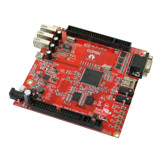
Page 14: Chapter 3: A13-Olinuxino Board Description
3. Introduction to the chapter Here you get acquainted with the main parts of the board. Note the names used on the board might differ from the names used below to describe them. For the actual names check the A13-OLinuXino board itself. -
Page 15: Chapter 4: The Allwinner A13 Microcontroller
OLIMEX© 2012 A13-OLinuXino user's manual CHAPTER 4: THE ALLWINNER A13 MICROCONTROLLER 4. Introduction to the chapter In this chapter is located the information about the heart of OLinuXino – its microcontroller. The information is a modified version of the datasheet provided by its manufacturers. - Page 16 OLIMEX© 2012 A13-OLinuXino user's manual SD Card V.3.0, eMMC V.4.2 SPI, TWI and UART integrated Audio Codec CSI R-TP Controller 4-wire resistive TP interface 2 points and gesture detection Boot Devices NAND Flash ...
-
Page 17: Block Diagram
OLIMEX© 2012 A13-OLinuXino user's manual 4.2 Block diagram The block diagram is taken from Allwinner's datasheet. Page 17 of 37 Elcodis.com electronic components distributor... -
Page 18: Chapter 5: Control Circuity
The power supply is handled mainly by AXP209 power management system, an Allwinner chip that goes together with the A13 processor. The power supply circuit of A13-OLinuXino allows flexible input supply from 6V to 16V. The minimum amperage suggested is 1A, and this threshold would rise if using all the three USB-HOSTs, a lot of GPIOs and LCD_con. -
Page 19: Chapter 6: Connectors And Pinout
UART1 interface allowing you to connect to an USB port. 6.1.1 USB communication The main way of communicating with the firmware of A13-OLinuXino is via the USB-OTG connector. You will also need a software tool “LiveSuit” and a newer firmware image if you wish to upgrade the firmware. -
Page 20: Uart1 Interface
Processor Pin # 3.3V SDC0_SCK SDC0_DATA3 Consider the above table when connecting the USB-SERIAL-CABLE-F according to the wire color code. If having A13-OLinuXino with 1xUART0 and the table with the signals can be found below: UART0 UART1 Pin # Signal Name... -
Page 21: Sd/Mmc Slot
The microSD card slot is a standard 8pin connector. The SD card can be used for booting the operating system for A13-OLinuXino. It is suggested to have an SD card with a proper Linux/Android image especially if you have ordered a version of the board without NAND memory. -
Page 22: Uext Module
OLIMEX© 2012 A13-OLinuXino user's manual 6.3 UEXT module A13-OLinuXino has an UEXT connector and can connect with Olimex's UEXT modules. For more information on UEXT please visit: https://www.olimex.com/Products/Modules/UEXT/resources/UEXT.pdf UEXT connector Pin # Signal Name Processor Pin # 3.3V UART1_TX UART1_RX... -
Page 23: Gpio-1 (General Purpose Input/Output) 10Pin Connector
OLIMEX© 2012 A13-OLinuXino user's manual 6.4 GPIO-1 (General Purpose Input/Output) 10pin connector The GPIO connector numbers are printed at the bottom of the board for your convenience. GPIO-1 Pin # Signal Name Processor Pin # 3.3V RESET_N NMI_N PIN0 PIN3... - Page 24 OLIMEX© 2012 A13-OLinuXino user's manual GPIO-2 connector Processor GPIO Pin# Signal Name Processor pin# GPIO Pin# Signal Name pin# 3.3V PIN4/TWI0-SCK PIN39/USBH_EN PIN5/TWI0-SDA PIN38/VGA_DIS PIN6 PIN37/LED1 PIN7 PIN36 PIN8 PIN35 PIN9 PIN34 PIN10/TWI1-SCK 105 PIN33 PIN11/TWI1-SDA 106 PIN32 Processor GPIO Pin# Signal Name...
-
Page 25: Lcd_Con 40Pin Connector
OLIMEX© 2012 A13-OLinuXino user's manual 6.6 LCD_CON 40pin connector The LCD_CON pins are led out on a separate 40pin connecter for the ease of connecting an LCD. We have tested the ability of the board to interact with such a display. They allow the user to attach additional hardware, check readings or perform hardware debug. -
Page 26: Pwr Jack
TPY1 TPY2 6.7 PWR Jack The power jack used is the typical 2.5mm one used by Olimex in most of our products. You should provide between 6 and 16 volts @ 1.5A maximum to the board. Pin # Signal Name... -
Page 27: Battery Connector
OLIMEX© 2012 A13-OLinuXino user's manual 6.9 Battery connector When using the battery connector keep in mind that it is an energy solution that wouldn't be able to power the board and all the peripherals. The voltage of a 3.7V LIPO battery would be enough to power the processor and the memory but won't be enough to power external touchscreen LCD. -
Page 28: Jumper Description
OLIMEX© 2012 A13-OLinuXino user's manual 6.8 Jumper description Please note that all the jumpers on the board are SMD type. If you feel insecure of your soldering/cutting technique it is better not to try to adjust the jumpers. The only really important jumper on the board is CE_NAND_E, which needs to be closed if you have board variant with NAND flash memory but you wish to boot OS from SD card. - Page 29 OLIMEX© 2012 A13-OLinuXino user's manual Reset button - used to reset the board 2 x 2Gb (512M x 8 bit) DDR3 SDRAM - the exact memory used in the first revisions of the board is hynix H5TQ2G83CFR-H9C 1 x 32Gb (4096M x 8 bit) NAND FLASH – the exact memory is hynix H27UBG8BTR – only present in A13-OLinuXino-WIFI LED1 + CHLED + PWR_LED –...
-
Page 30: Chapter 7: Schematics
(e.g. www.olimex.com). The EAGLE schematic is situated on the next page for quicker reference. Note that A13-OLinuXino-WIFI has all the components shown in the schematics. The stripped down version (A13-OLinuXino, without the -WIFI part) lacks two components: the NAND memory and the embedded WIFI module RTL8188CU. - Page 31 OLIMEX© 2012 A13-OLinuXino user's manual 2 x [2Gb DDR3 SDRAM (256Mx8)] 3.3V 1.2V_CPU 1.2V_INT 1.5V 3.0VA RM1G1 VCC1 RA0805_(4X0402)_22R DDR3_D0 1.5V 1.5V 1.5V RM3G4 RA0805_(4X0402)_22R VCC2 DDR3_D1 H5TQ2G83CFR-H9C H5TQ2G83CFR-H9C RM1G2 VCC3 RA0805_(4X0402)_22R DDR3_D2 RM3G3 VCC4 RA0805_(4X0402)_22R DDR3_D3 RM1G4 RA0805_(4X0402)_22R DDR3_D4...
-
Page 32: Physical Dimensions
OLIMEX© 2012 A13-OLinuXino user's manual 7.2 Physical dimensions Note that all dimensions are in mils. The three highest elements on the board in order from the tallest to the shortest are: capacitor C126 – 650mils, the three USB hosts – 500mils, the VGA connector - 475mils Page 32 of 37 Elcodis.com... -
Page 33: Chapter 8: Revision History And Support
OLIMEX© 2012 A13-OLinuXino user's manual CHAPTER 8: REVISION HISTORY AND SUPPORT 8. Introduction to the chapter In this chapter you will find the current and the previous version of the document you are reading. Also the web-page for your device is listed. Be sure to check it after a purchase for the latest available updates and examples. - Page 34 OLIMEX© 2012 A13-OLinuXino user's manual Continued from the previous page Revision Changes Modified Page# Pages 9, 10, 37 – added info about Android images Page 29 – fixed erroneous information about 9, 10, 29, 37 CE_NAND_E 31.10.12 Various pages – made it clear that the...
-
Page 35: Board Revision
1. Added BAT54C after Rx to UART1 connector 2. Added 100k pull-up resistor on the RX line 3. Changed wrong prints of the revision and the Olimex web-site 4. Some libraries updated and some component prints removed due to space... -
Page 36: Useful Web Links And Purchase Codes
A13-OLinuXino-WIFI – the full version of A13-OLinuXino with added NAND memory (Android image) and MOD-WIFI_RTL8188 A13-OLinuXino – the lite version of A13-OLinuXino with no external NAND and no embedded internet interface USB-SERIAL-CABLE-F - USB serial console cable for connecting to UART1 SY0612E - power supply adapter 12V/0.5A for A13-OLinuXino and A13-OLinuXino-WIFI... -
Page 37: Product Support
A13-OLinuXino user's manual 8.4 Product support For product support, hardware information and error reports mail to: support@olimex.com. Note that we are primarily a hardware company and our software support is limited. Please consider reading the paragraph below about the warranty of Olimex products.
Need help?
Do you have a question about the A13-OLinuXino and is the answer not in the manual?
Questions and answers