
Related Manuals for OLIMEX AVR-ISP500-ISO


Summary of Contents for OLIMEX AVR-ISP500-ISO
- Page 1 AVR-ISP500-ISO Users Manual All boards produced by Olimex are ROHS compliant Rev.C, October 2011 Copyright(c) 2011, OLIMEX Ltd, All rights reserved Page 1...
-
Page 2: Electrostatic Warning
PC. Next time button is pressed the programmer will invoke all previously recorded steps without the need for connection to the PC. We believe this feature makes AVR-ISP500-ISO the perfect tool for firmware upgrades in remote places. - Page 3 avrdude, included in the WinAVR distribution. Page 3...
-
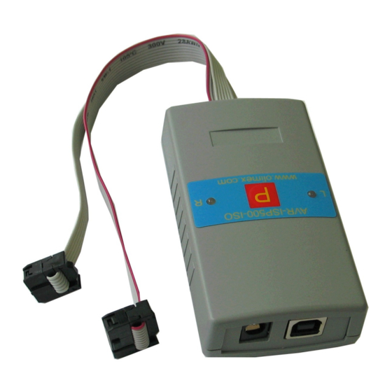
Page 4: Connector Schematics
SUPPORTED MICROCONTROLLERS: The following AVR microcontrollers are supported for programming: Classic 8-bit AVRs. megaAVR tinyAVR USB AVR The following AVR microcontrollers are not supported: XMEGA AVR32 The following programming methods are not supported: JTAG debugWire Parallel High Voltage Programming Serial High Voltage Programming CONNECTOR SCHEMATICS: ICSP10 Abbrev. - Page 5 3. Point the Device Wizard to the temporary directory. 4. Click finish. Screenshots of the steps are shown below: Page 5...
- Page 6 WARNING: The COM port number assigned by Windows to AVR-ISP500- ISO must be COM4 or below. Otherwise AvrStudio might not be able to detect the programmer. Here are the steps to change it: 1. Go to Device Manager. 2. Unfold “Ports (COM&LPT)” and right-click on “USB Serial Port (COMxx)”...
- Page 7 6. If a warning message pops up and complains about COM port being used by another device, click “Yes”. 7. Click OK to close the device properties. USING AVR-ISP500-ISO WITH AVRSTUDIO: WARNING: The COM port number assigned by Windows to AVR-ISP500- ISO must be COM4 or below.
- Page 8 Page 8...
- Page 9 Usage under AvrStudio is straightforward. First open the Programmer Connect dialog: Then select “STK500 or AVRISP option” with automatic port detection: After pressing “Connect” the programming dialog should appear: Page 9...
- Page 10 Page 10...
-
Page 11: Autonomous Operation
GREEN LED is on constantly. The right LED of AVR-ISP500-ISO is a bi-color LED which shows the last autonomous operation status for indefinite time. Again, RED is for error, GREEN is for success, off if no status is available due to ongoing operation. - Page 12 AVR-ISP500 STATES SHOW_RESULT if(error) STANDALONE_ISP LED0=on; LED1=off Finished LED0=on else if(empty) LED1=on LED0=blink_fast; LED1=off else LED0=off; LED1=blink_fast Button pressed 5 seconds passed or IDLE button pressed LED0=off LED1=on Button held for 1 second Button pressed Button released SHOW_LOG_STATUS ENABLE_LOGGING if(log_empty) LED0=blink_slow LED0=blink_fast Button held...
- Page 13 Example: LED1 LED0 Error code: 2 flashes – End of error code. LED0 idle idle mem read mismatch lights constantly. CAVEAT: RC calibration in autonomous mode is not supported. The reason is that the programmer has no way to distinguish RC value writes to FLASH from normal data ones.
- Page 14 TIP: If target signature must be verified during autonomous operation, READ SIGNATURE command must be issued while in command logging state. Page 14...
-
Page 15: Clock Output
CLOCK OUTPUT: Pin 3 of the ICSP10 connector is normally left unconnected by other ISP programmers. Not ours. In normal programmer state this pin is tri-stated. During programming operation, however, this pin is made output and a square-wave clock is generated. Clock frequency can be adjusted with the AvrStudio Programmer Dialog: After programming operation finishes, this pin is again tri-stated in order not to interfere with the target circuit. -
Page 16: Firmware Upgrade
User is free to use his favorite terminal client (HyperTerminal, minicom, etc) to upload the firmware images taken from our website. The serial port settings for the AVR-ISP500-ISO boot loader are: 9600 baud/sec, 8 data bits, no parity, 1 stop bit. The AVR-ISP500- TINY/MASS/NANO boot loaders implement a USB virtual serial port that is baudrate agnostic. - Page 17 ISP frequency might be too high. Set the ISP frequency to well below ¼ of target MCU clock. Please note that the AVR MCU clock depends on its fuses configuration. Target power might not be stable enough or supply voltage might be ...
-
Page 18: Electrical Characteristics
The target AVR MCU might have fuses programmed for disabling SPI ISP or selecting another programming method. In such case you'll need a High Voltage Parallel programmer to unlock the chip. The reset line cannot be pulled low by the programmer. Check your ... - Page 19 Symb Description Condition logging disabled, V =5V, TARG =2MHz Page 19...
-
Page 20: Order Code
ORDER CODE: AVR-ISP500-ISO – assembled and tested (no kit, no soldering required) How to order? You can order to us directly or by any of our distributors. www.olimex.com/dev Check our web for more info. Revision history: REV. A - create April 2008 REV. - Page 21 This document is intended only to assist the reader in the use of the product. OLIMEX Ltd. shall not be liable for any loss or damage arising from the use of any information in this document or any error or omission in such information or any incorrect use of the product.
- Page 22 Programmers - Processor Based Click to view products by manufacturer: Olimex Other Similar products are found below : TPG100004 TPG100017 X2S-FP-X CY8CKIT-005 ASBK-014 CMT WRITER ATB-USBASP MIKROPROG FOR 8051 MIKROPROG FOR PSOC5LP JTAG HS2 PROGRAMMING CABLE JTAG-SMT2-NC SM PROGRAMMING MODULE ZL30PRGV2-1 MIKROE-1505 MIKROPROG FOR AVR MIKROPROG FOR CEC MIKROPROG FOR PIC,DSPIC AND PIC32 MIKROPROG FOR STM32 MIKROPROG FOR TIVA ZL20PRG AVR-ISP500-TINY MIKROE-2511 CYBLE-012011-PROG CT210A-S 5.16.02 DC9010B...
Need help?
Do you have a question about the AVR-ISP500-ISO and is the answer not in the manual?
Questions and answers