
Related Manuals for OLIMEX ADuC-MT7020


Summary of Contents for OLIMEX ADuC-MT7020
- Page 1 ADuC-MT7020 development board Users Manual All boards produced by Olimex are ROHS compliant Rev. A, September 2005 Copyright(c) 2009, OLIMEX Ltd, All rights reserved Page 1...
-
Page 2: Board Features
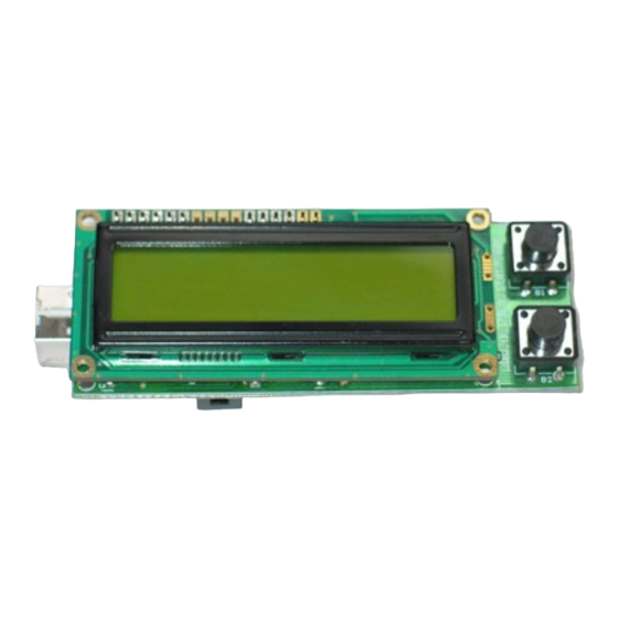
INTRODUCTION ADuC-MT7020 is small terminal board with USB link for PC, two buttons, LCD 16x2 with backlight and ADuC7020 with the unique 1Msps ADCs/DACs which are accessable on separate AEXT connector. BOARD FEATURES – MCU: ADuC7020 - ARM7TDMI Core, 16/32-bit RISC architecture, 5... -
Page 3: Electrostatic Warning
ELECTROSTATIC WARNING The ADuC-MT7020 board is shipped in protective anti-static packaging. The board must not be subject to high electrostatic potentials. General practice for working with static sensitive devices should be applied when working with this board. BOARD USE REQUIREMENTS Depends on the used programming/debugging tool. -
Page 4: Block Diagram
14-Pin GPIO Port – 2 X General Purpose Timers – Wake-up and Watchdog Timers – Power Supply Monitor – PLA – Programmable Logic (Array) – Power – Specified for 3V operation – Active Mode: 6mW (@1MHz) – 300mW (@45MHz) BLOCK DIAGRAM Page 4... -
Page 5: Memory Map
MEMORY MAP Page 5... - Page 6 SCHEMATIC P1.2 P0.4 BUT 1 P1.1 P1.0 P0.3 P0.3/TRST P4.2 DGND 470nF VREF LVDD VREF LVDD AGND IOVDD AVDD IOGND AVDD ADC0 100nF ADC0 T DO ADC1 ADC1 ADC2 P0.6 ADC2 P0.6 VCCIO VCC2 GND2 VCC1 Array GND1 EEPROM AVCC AGND Page 6...
-
Page 7: Board Layout
POWER CIRCUIT ADuC-MT7020 can take power from USB +5 V. RESET CIRCUIT ADuC-MT7020 reset circuit is includes R1 (1k) pull-up, U4 (MCP130T), ADuC7020 pin 19 and RST button. CLOCK CIRCUIT Quartz crystal 32.768 KHz is connected to ADuC7020 pin 24 (XCLKO) and pin 25 (XCLKI). -
Page 8: External Connectors Description
Reset button with name RST, connected to ADuC7020 pin 19 (RST). User button with name SD, connected to ADuC7020 pin 10 (P0.0). User button with name B1, connected to ADuC7020 pin 20 (P0.4). User button with name B2, connected to ADuC7020 pin 21 (P0.5). LCD 16x2 display with BACKLIGHT, connected as follows: RS –... - Page 9 AEXT Pin # Signal Name Pin # Signal Name AVDD AVDD ADC0 DAC0 ADC1 DAC1 ADC2 DAC2 ADC3 DAC3 ADC4 VREF Pin # Signal Name +3.3 V PIN # Signal Name +5V_USB USBDM USBDP Page 9...
-
Page 10: Mechanical Dimensions
MECHANICAL DIMENSIONS – All measures are in Inches. Page 10... -
Page 11: Available Demo Software
AVAILABLE DEMO SOFTWARE RS232 initialization for EW-ARM • LCD, DAC demo code for EW-ARM • LCD write for EW-ARM • ADC read DAC write demo code for EW-ARM • Blink LED demo code for EW-ARM • RS232 , UART, demo code for EW-ARM •... -
Page 12: Order Code
ORDER CODE ADuC-MT7020 - completely assembled and tested. How to order? You can order to us directly or by any of our distributors. Check our web www.olimex.com/dev for more info. Revision history: REV. A - create September 2005 Page 12... - Page 13 This document is intended only to assist the reader in the use of the product. OLIMEX Ltd. shall not be liable for any loss or damage arising from the use of any information in this document or any error or omission in such information or any incorrect use of the product.
Need help?
Do you have a question about the ADuC-MT7020 and is the answer not in the manual?
Questions and answers