Space-Ray LTU 160/100-N7 Installation And Operation Instructions Manual

Space-Ray LTU 160/100-N7 Installation And Operation Instructions Manual

Infrared radiant tube heater
Table of Contents

Advertisement

INSTALLATION AND OPERATION INSTRUCTIONS
OWNER / INSTALLER: For your safety this manual must be carefully and thoroughly read and
understood before installing, operating or servicing this heater.
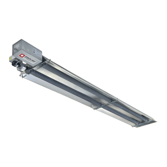
INFRARED RADIANT TUBE HEATER
Single and Two Stage Pull Through System (Negative Pressure)
LTU SERIES: (80, 90, 100, 110, 120, 125, 130, 140, 150, 160,
175, 180, 200, 225, 250) – N5/L5/N7/L7
LTS SERIES:
(40, 50, 60, 75, 80, 90, 100, 110, 120, 125, 130, 140, 150,
150, 160, 175, 180, 200, 225, 250) - N5/L5/N7/L7
!INSTALLER: This manual is the property of the owner. Please present this manual to the
owner when you leave the job site.
▲WARNING: Improper installation, adjustment, alteration, service, or maintenance can
cause property damage, injury or death. Read the installation, operation and maintenance
instructions thoroughly before installing or servicing this equipment.
IF YOU SMELL GAS:
! DO NOT try to light any appliance.
! DO NOT touch any electrical switch; DO NOT use any
telephone in your building.
! IMMEDIATELY call your gas supplier from a neighbor's
telephone. Follow the gas supplier's instructions. If you
cannot reach your gas supplier, call the fire department.
!IMPORTANT: SAVE THIS MANUAL FOR FUTURE REFERENCE.
Post Office Box 36485 (28236) • 305 Doggett Street (28203) • Charlotte, North Carolina
Phone (704) 372-6391 • Fax (704) 332-5843 • www.spaceray.com • email: info@spaceray.com
Models:
FOR YOUR SAFETY
DO NOT store or use gasoline or other
flammable vapors and liquids in the vicinity of
this or any other appliance.
SPACE-RAY
Form #43155010
Dec 2017

Advertisement

Table of Contents
loading

Summary of Contents for Space-Ray LTU 160/100-N7

  • Page 1 !IMPORTANT: SAVE THIS MANUAL FOR FUTURE REFERENCE. SPACE-RAY Post Office Box 36485 (28236) • 305 Doggett Street (28203) • Charlotte, North Carolina Phone (704) 372-6391 • Fax (704) 332-5843 • www.spaceray.com • email: info@spaceray.com...
  • Page 2: Table Of Contents

    TABLE OF CONTENTS SECTION DESCRIPTION PAGE 1.0) Safety ..............................2 2.0) Installer Responsibility ........................2 3.0) General Information ........................... 2 4.0) Minimum Clearances to Combustibles ................... 4 5.0) Typical Suspension Methods ......................5 6.0) LTU Series Specifications ........................6 7.0) LTU Series Packing List ........................
  • Page 3: Safety

    LTS/LTU 225-250 models. Heaters may be mounted at various heights and angles depending on the application. If you have any questions, please consult your local Space-Ray representative. Every heater shall be located with respect to building construction and other equipment so as to permit access to the heater.
  • Page 4 8 feet. Although these heaters may be used in many applications other than space heating (e.g., process heating), Space-Ray will not recognize the warranty for any use other than space heating. For indoor installation only. Not for use in residential dwellings.
  • Page 5: Minimum Clearances To Combustibles

    NFPA54 requires that the installer must post signs that will “specify the maximum permissible stacking height to maintain the required clearances from the heater to combustibles.” Space-Ray recommends posting these signs adjacent to the heater thermostat or other suitable location that will provide enhanced visibility.
  • Page 6: Typical Suspension Methods

    6. Heaters must not be supported by gas or electric supply lines and must be suspended from a permanent structure with adequate load capacity. Space-Ray recommends that the body sections be suspended using chains with turnbuckles. This will allow slight adjustments after assembly and heater expansion/ contraction during operation.
  • Page 7: Ltu Series Specifications

    19 ft. * MOUNT HEATERS AS HIGH AS POSSIBLE. Minimums are shown as a guideline for human comfort and uniform energy distribution for complete building heating applications. Consult your Space-Ray representative for the particulars of your installation requirements. Model Identification:...
  • Page 8: Ltu Series Packing List

    LTU 140-N5 42883190 NATURAL LTU 140/89-N7 42883650 NATURAL LTU 150-N5 42883210 NATURAL LTU 150/95-N7 42883670 NATURAL LTU 160-N5 42883230 NATURAL LTU 160/100-N7 42883690 NATURAL LTU 175-N5 42883250 NATURAL LTU 175/110-N7 42883710 NATURAL LTU 180-N5 42883270 NATURAL LTU 180/114-N7 42883730 NATURAL...
  • Page 9 (Package Part Number is indicated on the outside of each corresponding carton.) 15’ Body Pkg. 5’ Body Pkg. 10’ Body Pkg. 10’ Body Pkg. 42881000 42882000 42882020 42882030 System Lengths Qty. Qty. Qty. Qty. 30’ 40’ 50’ * 50’ ** * for LTU 180-200 Models Only;...
  • Page 10: Ltu Series Typical Layouts

    8.0) LTU SERIES TYPICAL LAYOUTS EMITTER MODEL LENGTH 30’ LTU 80, 90, 100, 110, 120, 125, 130 40’ LTU 125, 130, 140, 150, 160, 175 50’ LTU 180, 200, 225, 250 NOTES: 1. In all configurations, the control unit must be connected directly to either a) the 12-radial hole flange of the aluminized steel body section (for LTU 80-200 models) or b) the 6-hole flange of the 10 ft.
  • Page 11 Models: LTU 125-175 Models: LTU 180-250 Form #43155010 -10- Dec 2017...
  • Page 12: Ltu 80-175 Series Heater Assembly Overview

    8.2) LTU 80-175 SERIES HEATER ASSEMBLY OVERVIEW Form #43155010 Dec 2017 -11-...
  • Page 13: Ltu 180-250 Series Heater Assembly Overview

    8.3) LTU 180-250 SERIES HEATER ASSEMBLY OVERVIEW Models: LTU 180-200 Models: LTU 225-250 8.4) LTU SERIES 15’ BODY PACKAGE OPENING Follow the procedure below to open the 15’ body package. 1. Remove end reflectors from packaging. 2. Lift the tube at the flange end, then slide tube support/hanger bracket between marks on tubes and tighten the “U”...
  • Page 14: Ltu 80-130 Series Heater Assembly

    8.5) LTU 80-130 SERIES HEATER ASSEMBLY During field assembly of the heater, the recommended procedure is as follows: 1. Install the suspension (according to Section 8.1) using proper suspension method (see Section 5.0). Trapeze Method Individual Suspension Method 2. Lift the body section and suspend it into place. When lifting, caution should be used to avoid damaging the assembly.
  • Page 15 3. Assembly the reflectors onto the body section. Leave 3” space between the tube flange and the first reflector for later mounting of control box and draft inducer. 4. Place the flanges of the control end reflector flush with the end of the first reflector. Secure by sliding speed clips onto reflector edges.
  • Page 16 7. Insert SJO cable through the strain relief bushing of the control box and connect to L1 and L2 of terminal block. Refer also to the wiring diagram in Section16.0). 8. Reflectors should overlap 1” to 3” and must be secured by sliding speed clips on the reflector edges. One speed clip is required for each side of the reflector.
  • Page 17: Ltu 125-250 Series - Joining Of 5' And 10' Body Sections

    8.6) LTU 125-250 SERIES – JOINING OF 5’ AND 10’ BODY SECTIONS These models require the use of an additional 5’ body section for LTU 125-175 and 10’ body section for LTU 180- 250, as shown in Section 8.1). Follow the instruction below for joining these sections. 1.
  • Page 18: Lts Series Specifications

    19 ft. * MOUNT HEATERS AS HIGH AS POSSIBLE. Minimums are shown as a guideline for human comfort and uniform energy distribution for complete building heating applications. Consult your Space-Ray representative for the particulars of your installation requirements. Model Identification:...
  • Page 19: Lts Series Packing List

    10.0) LTS SERIES PACKING LIST A. Control/Draft Inducer Package Part Description Control Box Assembly ..........................1 Draft Inducer & Junction Box Assembly ....................1 Flue Restrictor Plate (See Section 8.6) for plate I.D. and part no.) ........... 1 4” x 6” Starting Collar (#42892009) Supplied with LTS 180-250 ..........
  • Page 20 LTS 175-L5 42883260 PROPANE LTS 175/110-L7 42883720 PROPANE LTS 180-L5 42883280 PROPANE LTS 180/114-L7 42883740 PROPANE LTS 200-L5 42883300 PROPANE LTS 200/125-L7 42883760 PROPANE LTS 225-L5 42883320 PROPANE LTS 225/146-L7 42883780 PROPANE LTS 250-L5 42883340 PROPANE LTS 250/162-L7 42883800 PROPANE B.
  • Page 21 C. LTS 225-250 Body Package Descriptions (Package Part Number is indicated on the outside of each corresponding carton.) 10’ Start Pkg. (ATC) 10’ Start/End Pkg. (ALC) 10’ Extension/End Pkg. 5’ End Pkg. 43337050 43337040 43337010 43336030 System Lengths Qty. Qty. Qty.
  • Page 22: Lts Series Typical Layouts

    11.0) LTS SERIES TYPICAL LAYOUTS NOTES: 1. In all configurations, the control unit must be connected directly to either a) the 12-radial hole flange of the 10 ft. aluminized steel start/end body section (for LTS 40-200 models) or b) the 6-hole flange of the 10 ft. alumi-therm steel starting body section (for LTS 225 and 250 models).
  • Page 23: Lts Series Dimensions

    11.1) LTS SERIES DIMENSIONS Typical Dimensions Up to 50 Ft. Shown Form #43155010 -22- Dec 2017...
  • Page 24: Lts 40-175 Series Heater Assembly Overview

    11.2) LTS 40-175 SERIES HEATER ASSEMBLY OVERVIEW Form #43155010 Dec 2017 -23-...
  • Page 25: Lts 180-250 Series Heater Assembly Overview

    11.3) LTS 180-250 SERIES HEATER ASSEMBLY OVERVIEW Models: LTS 180-200 Models: LTS 225-250 11.4) LTS SERIES HEATER ASSEMBLY During field assembly of the LTS series heater body sections, the recommended procedure is as follows: 1. Before hanging heater sections, first determine the actual layout of the system (see Sections 11.0) & 11.1) for details).
  • Page 26 4. Join the body sections together and secure with tube couplings as follows: The following coupling tightening instructions MUST be followed properly to ensure the integrity of the tube connections. Two #10 self-drilling screws MUST be installed at every coupling as shown in the instructions below.
  • Page 27 5. For LTS225-250 Models, join the first two body sections as illustrated below. a) Join the tube flanges of the body sections together with the gasket in between. Loosely attach the heater body sections together with the ¼-20 screws and locknuts provided. DO NOT fully tighten the screws and locknuts yet! b) Tighten the screws and locknuts using the sequence shown.
  • Page 28 6. Assemble reflectors onto the body sections. Reflectors should overlap 1” to 2” and must be secured with each other by sliding speed clips on the reflector edges. One speed clip is required for each side of the reflectors. 7. Fasten reflectors to all of the tube support/hanger brackets as marked per (DETAIL–A) with (2) #10 sheet metal screws.
  • Page 29: Lts Series - Adding Optional 90º Elbow

    11.5) LTS SERIES - ADDING OPTIONAL 90º ELBOW 1. The optional 90º elbow must be located a minimum of 10 ft. after the control box. 2. Hang the body sections in a 90º ("L") shaped pattern. Allow spacing for the elbow. The distance from one end of the elbow to the centerline of the opposite leg is 13"...
  • Page 30: Lts Series - Attaching Draft Inducer Assembly

    5. The heater can be mounted horizontally or at an angle of up to 45 degrees maximum from horizontal. When angle mounting, the control box must be positioned upright. Failure to install the control box in an upright position will VOID the manufacturer’s warranty. For additional instructions see Section 13.0) for multiple hanging and draft inducer positions.
  • Page 31: Lts Series - Inclined Mounting Instructions

    11.9) LTS SERIES - INCLINED MOUNTING INSTRUCTIONS These inclined mounting instructions relate to LTS series heaters (straight tubes) that do not utilize the elbow accessory. These heaters have been tested and design certified by the CSA for 2”/12” pitch (10º) inclined mounting of the heater from the control box to the draft inducer assembly as shown in the following diagram.
  • Page 32 The purpose of this type mounting is to allow the heater to be mounted in the plane of the roof (particularly in modern “Butler” type buildings frequently used today). This will typically put the heater out of the way while still providing the warmth and comfort.
  • Page 33: Accessory Packages

    12.0) ACCESSORY PACKAGES A. Elbow Accessory Package, Part #43208010 (Option for LTS Series Only) Contains: Elbow, #43175000……QTY–1 #10-16 x ½ Self-Drilling Screws, #02189020……QTY–2 Tube Coupling, #30462980……QTY–1 B. Corner Reflector Accessory Package, Part #43342000 (Option for LTS Series Only) Contains: Corner Reflector Assembly, #43345000……QTY–1 Speed Clips, #02266010……QTY–4 C.
  • Page 34 2. Pull the motor and blower wheel assembly with the motor plate slightly from the end of the housing studs. Use care not to damage the motor leads. 3. Rotate the junction box assembly to the upright position using the multi-hole mounting bracket. 4.
  • Page 35: Gas Connections And Regulations

    14.0) GAS CONNECTIONS AND REGULATIONS IMPORTANT BEFORE CONNECTING THE GAS TO THE HEATER 1. Connect to the supply tank or manifold in accordance with the latest edition of National Fuel Gas Code (ANSI Z223.1), and local building codes. Authorities having jurisdiction should be consulted before the installation is made.
  • Page 36 US ONLY: Connector MUST be installed in “” configuration. Use only the 36” long connector that was furnished with this heater. US ONLY: A gas connector certified for use on a tubular type infrared heater per the standard for Connectors for Gas Appliances, ANSI Z21.24/CSA 6.10 is supplied for installation in US only.
  • Page 37: Instructions For Pressure Test Gauge Connection

    15.0) INSTRUCTIONS FOR PRESSURE TEST GAUGE CONNECTION SUPPLY PRESSURE 1. The installer will provide a 1/8” N.P.T. tapped plug, accessible for test gauge connection immediately upstream of the gas supply connection to the heater. OUTLET GAS PRESSURE CHECK AND ADJUSTMENTS WHITE-RODGERS GAS VALVES Gauges that measure pressure in pounds per square inch are not accurate enough to measure or set the manifold pressure.
  • Page 38: Electrical Connections

    GAS PRESSURE TABLE SUPPLY PRESSURE MANIFOLD PRESSURE GAS TYPE High Low (2-stage only) Minimum* Maximum Natural Gas 3.5” W.C. 1.4” W.C. 5” W.C. 14” W.C. Propane Gas 10.0” W.C. 4.0” W.C. 11” W.C. 14” W.C. *Minimum permissible gas supply pressure for purpose of input adjustment. 7”...
  • Page 39: 16.1 Single Stage (N5/L5) - Internal And Thermostat Connections

    5. When connecting the supply circuit to the heater, wiring material having a minimum size of 14 AWG and a temperature rating of at least 90C shall be used. 6. If any of the original wire as supplied with the appliance must be replaced, it must be replaced with wiring material having a temperature rating of at least 105ºC.
  • Page 40 SINGLE STAGE CONTROLS - SCHEMATIC WIRING DIAGRAM SINGLE STAGE CONTROLS - THERMOSTAT WIRING DIAGRAMS A. LINE VOLTAGE (120V) THERMOSTAT CONNECTIONS – SINGLE HEATER PER THERMOSTAT B. LINE VOLTAGE (120V) THERMOSTAT CONNECTIONS – MULTIPLE HEATERS PER THERMOSTAT Form #43155010 Dec 2017 -39-...
  • Page 41: 16.2 Two Stage (N7/L7) - Internal And Thermostat Connections

    C. LOW VOLTAGE (24V) THERMOSTAT CONNECTIONS – SINGLE HEATER PER THERMOSTAT Order 24V Relay Kit (Part No. 43274010) for Low Voltage (24V) thermostat connection. LOW VOLTAGE (24V) THERMOSTAT CONNECTIONS – MULTIPLE HEATERS PER THERMOSTAT 16.2 TWO STAGE (N7/L7) – INTERNAL AND THERMOSTAT CONNECTIONS Form #43155010 -40- Dec 2017...
  • Page 42 9. LTS SERIES TWO-STAGE CONTROLS ONLY: The installer will provide type 3 core SJO cable having minimum size of 18 AWG to connect between the draft inducer junction box and the control box. See wiring diagram below. Secure with 3/8” connectors as previously described in the attachment of the control box and draft inducer.
  • Page 43 TWO STAGE CONTROLS - THERMOSTAT WIRING DIAGRAMS A. LOW VOLTAGE (24V) THERMOSTAT CONNECTIONS – SINGLE HEATER PER THERMOSTAT B. LOW VOLTAGE (24V) THERMOSTAT CONNECTIONS – MULTIPLE HEATERS PER THERMOSTAT Form #43155010 -42- Dec 2017...
  • Page 44 C. MANUAL SWITCH CONNECTIONS – SINGLE HEATER OPERATION PER DUAL MANUAL SWITCH D. MANUAL SWITCH CONNECTIONS – MULTIPLE HEATERS OPERATION PER DUAL MANUAL SWITCH Form #43155010 Dec 2017 -43-...
  • Page 45: Venting

    17.0) VENTING This is a category lll appliance. A. BASIC FLUE VENTING — Venting must comply with the latest edition of the National Fuel Gas Code (ANSI Z223.1-latest edition) or the authority having jurisdiction. Other venting references are in the equipment volume of the ASHRAE Handbook.
  • Page 46 SINGLE HEATER VENTING (HORIZONTAL THROUGH SIDEWALL) When venting the heater horizontally through a combustible outside sidewall, the same requirements listed previously for venting Vertical Through The Roof apply except as follows: 1. A vent passing through a combustible wall must pass through an approved clearance thimble (Air-Jet #4VT or Ameri-Vent #4EWT or other thimbles) that are listed by a nationally recognized testing agency.
  • Page 47 MULTIPLE HEATER VENTING (CONNECTIONS INTO A COMMON VENT OR MANIFOLD) Requirements for venting of multiple heaters are the same as described for SINGLE HEATER VENTING except as follows: 1. The common vent size and total vent height is normally determined by the number of heaters per common vent, length of horizontal connector runs, and connector rise.
  • Page 48 Multiple Heater Horizontal Venting Arrangement Multiple Heater Venting (Connections into a Manifold) VENT SIZING TABLE — Multiple Heater Venting Number of Heaters LTU40-50 4” 4” 5” 5” 6” LTU60-75 4” 5” 6” 6” 7” LTS/U80-100 4” 6” 6” 7” 8” LTS/U110-130 4”...
  • Page 49: Air For Combustion

    B. INDIRECT VENTING (UNVENTED HEATERS) — This heater requires ventilation in the building to dilute the products of combustion and provide fresh air for efficient combustion. Where unvented heaters are used, gravity or mechanical means shall be provided to supply and exhaust at least 4 CFM per 1,000 Btu/hr input of installed heaters.
  • Page 50 All vent terminations and Combustion Air Intake Terminations must be at least 6” higher than anticipated snow depth. In multiple heater applications, the combustion air intake may be ducted individually or common ducted in the same configuration as shown for venting in Section 17.0). For combustion air intake duct sizing, please refer to the Vent Sizing Table and use the diameter indicated, based on the number of heaters per duct.
  • Page 51: Lighting And Shutdown Instructions

    19.0) LIGHTING AND SHUTDOWN INSTRUCTIONS 1. Turn on the gas and electrical supply. Rotate the gas valve knob counter-clockwise  to the “ON” position. 2. Set the thermostat to call for heat. The blower motor will energize. 3. Ignition should occur after the 30-second air pre-purge. 4.
  • Page 52: Sequence Of Operation - Two Stage (N7/L7)

    20.1) SEQUENCE OF OPERATION – TWO STAGE (N7/L7) The chart below shows the sequence of operation for the normal operating cycle for a two stage heater (N7/L7). .If the flame is not sensed during sequence T3 or T4, then the burner will automatically begin ignition as in sequence T2.
  • Page 53: Cleaning And Annual Maintenance

    21.0) CLEANING AND ANNUAL MAINTENANCE This heater must be cleaned and serviced annually by a qualified contractor before the start of each heating season and at any time excessive accumulation of dust and dirt is observed. Maximum heating efficiency and clean combustion will be maintained by keeping the heater clean.
  • Page 54: Troubleshooting Guide - Single Stage (N5/L5)

    22.0) TROUBLESHOOTING GUIDE – SINGLE STAGE (N5/L5) Form #43155010 Dec 2017 -53-...
  • Page 55 TROUBLESHOOTING GUIDE – SINGLE STAGE (CONTINUED) Form #43155010 -54- Dec 2017...
  • Page 56 TROUBLESHOOTING GUIDE – SINGLE STAGE (CONTINUED) Form #43155010 Dec 2017 -55-...
  • Page 57: Troubleshooting Guide - Two Stage (N7/L7)

    22.1) TROUBLESHOOTING GUIDE – TWO STAGE (N7/L7) Form #43155010 -56- Dec 2017...
  • Page 58 TROUBLESHOOTING GUIDE – TWO STAGE (CONTINUED) Form #43155010 Dec 2017 -57-...
  • Page 59 TROUBLESHOOTING GUIDE – TWO STAGE (CONTINUED) Form #43155010 -58- Dec 2017...
  • Page 60 TROUBLESHOOTING GUIDE – TWO STAGE (CONTINUED) Form #43155010 Dec 2017 -59-...
  • Page 61: Replacing Parts

    23.0) REPLACING PARTS Only use genuine Space-Ray replacement parts. Parts are available from the factory for replacement by a licensed person. Refer to the Replacement Parts Guide in Section 25.0) for all replacement parts. 23.1) REMOVING SPARK ELECTRODE The main burner can be inspected without removing the burner housing from the heat exchanger tube.
  • Page 62: Air Switch Pressure Check

    1. Disconnect electrical supply and gas connection at the restrainer nipple. 2. Open the access panel and disconnect the wires from gas valve. 3. Remove the burner clamp and screws. 4. Remove the burner and gas valve assembly from the cabinet. 5.
  • Page 63: Motor And Blower Wheel Check

    TO CHECK SPARK IGNITION CIRCUIT. ▲WARNING: The ignition circuit generates a 20,000 Volt open circuit and electrical shock can result. a. Check ignition cable. b. Check external fuse located inside the draft inducer junction box. Verify power (24V) at module input terminals and output terminal to gas valve. d.
  • Page 64: Installation Data

    24.0) INSTALLATION DATA Date of # of Heaters in Installation: System: Serial No. N = Natural Gas Model: LTS or LTU L = Propane Gas Form #43155010 Dec 2017 -63-...
  • Page 65: Replacement Parts Guide

    25.0) REPLACEMENT PARTS GUIDE DRAFT INDUCER COMPONENTS Item No. Part No. Description 42917000 Draft Inducer Assembly, 40M–175M Btu/hr models (1-stage controls) 42917010 Draft Inducer Assembly, 180M–250M Btu/hr models (1-stage controls) 42917500 Draft Inducer Assembly, 40M–175M Btu/hr models (2-stage controls) 42917510 Draft Inducer Assembly, 180M–250M Btu/hr models (2-stage controls) 42928000 Motor Replacement Kit, 40M–175M Btu/hr models...
  • Page 66 Labels Item No. Part No. Description Qty. 42874000 Label, Wire Diagram – (1-stage controls) 42874040 Label, Wire Diagram – (2-stage controls) 42922020 Label, Sidewall Venting 43269060 Label, 24V Thermostat Connection – (2-stage controls) Form #43155010 Dec 2017 -65-...
  • Page 67 Label, Wire Diagram – Connections (2-stage controls) 42875000 Label, Warning 43269000 Label, 24V Supply 43270000 Label, Terminal ID (terminals 1 & 2) 24V Supply 42013000 Label, “Space-Ray” Logo 42848000 Label, “Space-Ray” Nameplate (1-stage controls) 42848110 Label, “Space-Ray” Nameplate (2-stage controls) Form #43155010 -66- Dec 2017...
  • Page 68 43344000 Label, Clearance to Combustibles 43344050 Label, Gas Connector Warning 43269070 Label, Low/High Fire (2-stage controls) Form #43155010 Dec 2017 -67-...
  • Page 69 BODY COMPONENTS: LTS 40-250 Item Part No. Description 02266010 Reflector Speed Clip 42769011 Reflector Clamp with Screw 42873000 “U” Bolt Clamp, 4” OD Tube 02127110 5/16-18 Hex Nut (2 per “U” Bolt) 43318000 Tube Support/Hanger Bracket, 13” (2 per 5 ft. or 10 ft. body section) 43319050 Reflector, 4’-11½”...
  • Page 70 ALL ILLUSTRATIONS ARE INTENDED TO GIVE THE GENERAL IMPRESSION OF UNITS ONLY. OTHER COMBINATIONS OF 5 FT. AND 10 FT. SECTIONS, AND ONES WITH OR WITHOUT THE ELBOW PACKAGE ARE POSSIBLE. PLEASE CONSULT WITH YOUR SPACE-RAY SALES REPRESENTATIVE. WE RESERVE THE RIGHT TO ALTER ANY SPECIFICATION WITHOUT NOTICE.
  • Page 71: 26.0) Warnings Card

    26.0) WARNINGS CARD Copies of this card may be ordered at no charge under part no. 43344990 for installation near the heater. Form #43155010 -70- Dec 2017...

Table of Contents