Table of Contents
Advertisement
Quick Links
INSTALLATION AND OPERATION INSTRUCTIONS
OWNER / INSTALLER: For your safety this manual must be carefully and thoroughly read and
understood before installing, operating or servicing this heater.
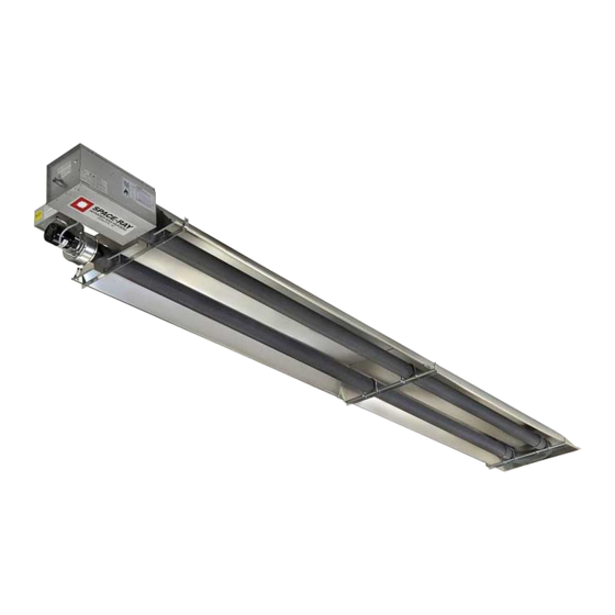
INFRARED RADIANT TUBE HEATER
Single Stage Pull Through System (Negative Pressure)
!INSTALLER: This manual is the property of the owner. Please present this manual to the
owner when you leave the job site.
▲WARNING: Improper installation, adjustment, alteration, service, or maintenance can
cause property damage, injury or death. Read the installation, operation and maintenance
instructions thoroughly before installing or servicing this equipment.
IF YOU SMELL GAS:
! DO NOT try to light any appliance.
! DO NOT touch any electrical switch; DO NOT use any
telephone in your building.
! IMMEDIATELY call your gas supplier from a neighbor's
telephone. Follow the gas supplier's instructions. If you
cannot reach your gas supplier, call the fire department.
!IMPORTANT: SAVE THIS MANUAL FOR FUTURE REFERENCE.
Post Office Box 36485 (28236) • 305 Doggett Street (28203) • Charlotte, North Carolina
Phone (704) 372-6391 • Fax (704) 332-5843 • www.spaceray.com • email: info@spaceray.com
Models:
LTU SERIES
LTU40 – (N5/L5)
LTU50 – (N5/L5)
LTU60 – (N5/L5)
LTU75 – (N5/L5)
FOR YOUR SAFETY
DO NOT store or use gasoline or other
flammable vapors and liquids in the vicinity of
this or any other appliance.
SPACE-RAY
Form #42710000
Mar 09
Advertisement
Table of Contents

Related Manuals for Space-Ray LTU40-N5


Summary of Contents for Space-Ray LTU40-N5
-
Page 1: Installation And Operation Instructions
!IMPORTANT: SAVE THIS MANUAL FOR FUTURE REFERENCE. SPACE-RAY Post Office Box 36485 (28236) • 305 Doggett Street (28203) • Charlotte, North Carolina Phone (704) 372-6391 • Fax (704) 332-5843 • www.spaceray.com • email: info@spaceray.com... -
Page 2: Table Of Contents
TABLE OF CONTENTS SECTION DESCRIPTION PAGE 1.0) Safety ..............................2 2.0) Installer Responsibility ........................2 3.0) General Information........................... 2 4.0) Minimum Clearances to Combustibles................... 4 5.0) Specifications............................5 6.0) Packing List............................5 6.1) Accessory Packages .......................... 6 7.0) Dimensions – LTU(40-75)-30 Series ....................6 8.0) Heater Assembly Overview ....................... -
Page 3: Safety
1.0) SAFETY This heater is a self-contained infrared radiant tube heater. Safety information required during installation and operation of this heater is provided in this manual and the labels on the product. The installation, service and maintenance of this heater must be performed by a contractor qualified in the installation and service of gas fired heating equipment. - Page 4 Although these heaters may be used in many applications other than space heating (e.g., process heating), Space-Ray will not recognize the warranty for any use other than space heating. This heater is for Indoor Installation and Covered Patio Installation only and can be used in either Vented or Unvented mode.
-
Page 5: Minimum Clearances To Combustibles
NFPA54 requires that the installer must post signs that will “specify the maximum permissible stacking height to maintain the required clearances from the heater to combustibles.” Space-Ray recommends posting these signs adjacent to the heater thermostat or other suitable location that will provide enhanced visibility. -
Page 6: Specifications
13’ 12’ * MOUNT HEATERS AS HIGH AS POSSIBLE. Minimums are shown as a guideline for human comfort and uniform energy distribution for complete building heating applications. Consult your Space-Ray representative for the particulars of your installation requirements. Type Gas Pipe... -
Page 7: Accessory Packages
6.1) ACCESSORY PACKAGES A. Exhaust Hood Package, Part #42924000 Contains: Exhaust Hood Assembly, #42925540……QTY–1 #8-18 x ½ Self-Drilling Screws, #02189030……QTY–2 7.0) DIMENSIONS – LTU(40-75)-30 SERIES Form #42710000 Mar 09... -
Page 8: Heater Assembly Overview
8.0) HEATER ASSEMBLY OVERVIEW Form #42710000 Mar 09... -
Page 9: Typical Suspension Methods
6. Heaters must not be supported by gas or electric supply lines and must be suspended from a permanent structure with adequate load capacity. Space-Ray recommends that the tube sections be suspended using chains with turnbuckles. This will allow slight adjustments after assembly and heater expansion/ contraction during operation. -
Page 10: Heater Assembly
10.0) HEATER ASSEMBLY During field assembly of the heater, the recommended procedure is as follows: 1. Put the suspension in place (according to Section 7.0) using proper suspension method (see Section 9.0). Trapeze Method Individual Suspension Method 2. Lift the tube section and suspend it into place. When lifting, caution should be used to avoid damaging the assembly. - Page 11 3. Assembly the reflectors onto the tube section. Leave 3” space between the tube flange and the first reflector for later mounting of control box and draft inducer. 4. Place the flanges of the control end reflector flush with the end of the first reflector. Secure by sliding speed clips onto reflector edges.
- Page 12 7. Slip the plastic vacuum air tube over the 1/4” O.D. aluminum tube end of the draft inducer and the air switch probe in the control box. The air tube should be shortened to prevent a downward sag which could allow condensation build-up in the tube.
-
Page 13: Gas Connections And Regulations
ANGLE MOUNTED HEATERS ONLY 11. The heater can be mounted horizontally or up to an angle of 45º maximum from horizontal. When the heater is to be angle mounted adjacent to a sidewall, make sure the draft inducer assembly is on the lower side of the heater so that the control box access panel is easily accessible. - Page 14 10. After all gas connections have been made, make sure the heater and all gas outlets are turned off before the main gas supply is turned on slowly. Turn the gas supply pressure on and check for leaks. To check for leaks, check by one of the methods listed in Appendix D of the National Fuel Gas Code.
-
Page 15: Instructions For Pressure Test Gauge Connection
12.0) INSTRUCTIONS FOR PRESSURE TEST GAUGE CONNECTION SUPPLY PRESSURE 1. The installer will provide a 1/8” N.P.T. tapped plug, accessible for test gauge connection immediately upstream of the gas supply connection to the heater. MANIFOLD PRESSURE – COMBINATION GAS VALVE IS FACTORY SET 1. -
Page 16: Electrical Connections
13.0) ELECTRICAL CONNECTIONS 1. All electric wiring shall conform to the latest edition of the National Electrical Code (ANSI/NFPA No. 70), or the code legally authorized in the locality where the installation is made. 2. The unit must be electrically grounded in accordance with the National Electrical Code (ANSI/NFPA No. 70-latest edition). - Page 17 SCHEMATIC WIRING DIAGRAM — Direct Spark Ignition Moteur Témoin vert Transformateur 24ÊV Témoin rouge pressostat Bloc d'allumage électrode Robinet à gaz Témoin ambre FIELD CONNECTION AND THERMOSTAT WIRING DIAGRAMS A. LINE VOLTAGE (120V) THERMOSTAT CONNECTIONS – SINGLE HEATER PER THERMOSTAT B.
- Page 18 C. LOW VOLTAGE (24V) THERMOSTAT CONNECTIONS – SINGLE HEATER PER THERMOSTAT Order 24V Relay Kit (Part No. 43274000) for Low Voltage (24V) thermostat connection. NOTES: 1. If any of the original wire as supplied with the appliance must be replaced, it must be replaced with wiring material having a temperature rating of at least 105ºC.
-
Page 19: Venting
14.0) VENTING A. BASIC FLUE VENTING — Venting must comply with the latest edition of the National Fuel Gas Code (ANSI Z223.1-latest edition) or the authority having jurisdiction. Other venting references are in the equipment volume of the ASHRAE Handbook. Heat Maximum Fresh air Maximum vent length ft. - Page 20 10. A venting system shall terminate at least 3 ft. above any forced air inlet located within 10 ft. SINGLE HEATER VENTING (HORIZONTAL THROUGH SIDEWALL) When venting the heater horizontally through a combustible outside sidewall, the same requirements listed previously for venting Vertical Through The Roof apply except as follows: 1.
- Page 21 MULTIPLE HEATER VENTING (CONNECTIONS INTO A COMMON VENT OR MANIFOLD) Requirements for venting of multiple heaters are the same as described for SINGLE HEATER VENTING except as follows: 1. The common vent size and total vent height is normally determined by the number of heaters per common vent, length of horizontal connector runs, and connector rise.
- Page 22 Multiple Heater Horizontal Venting Arrangement Multiple Heater Venting (Connections into a Manifold) VENT SIZING TABLE — Multiple Heater Venting Number of Heaters LTU 40 4” 4” 5” 5” 6” LTU 50 4” 4” 5” 5” 6” LTU 60 4” 5” 6”...
-
Page 23: Air For Combustion
B. INDIRECT VENTING (UNVENTED HEATERS) — This heater requires ventilation in the building to dilute the products of combustion and provide fresh air for efficient combustion. Where unvented heaters are used, gravity or mechanical means shall be provided to supply and exhaust at least 4 CFM per 1,000 Btu/hr input of installed heaters. - Page 24 In multiple heater applications, the combustion air intake may be ducted individually or common ducted in the same configuration as shown for venting in Section 14.0). For combustion air intake duct sizing, please refer to the Vent Sizing Table and use the diameter indicated, based on the number of heaters per duct. Form #42710000 Mar 09 -23-...
-
Page 25: Lighting And Shutdown Instructions
16.0) LIGHTING AND SHUTDOWN INSTRUCTIONS 1. Turn on the gas and electrical supply. Rotate the gas valve knob counter-clockwise to the “ON” position. 2. Set the thermostat to call for heat. The blower motor will energize. 3. Ignition should occur after the 30-second air pre-purge. 4. -
Page 26: Control Component Location
18.0) CONTROL COMPONENT LOCATION NOTE: Access panel only opens to 90°. Form #42710000 Mar 09 -25-... -
Page 27: Cleaning And Annual Maintenance
19.0) CLEANING AND ANNUAL MAINTENANCE This heater must be cleaned and serviced annually by a qualified contractor before the start of each heating season and at any time excessive accumulation of dust and dirt is observed. Maximum heating efficiency and clean combustion will be maintained by keeping the heater clean. -
Page 28: Troubleshooting Guide
20.0) TROUBLESHOOTING GUIDE Form #42710000 Mar 09 -27-... - Page 29 Form #42710000 -28- Mar 09...
- Page 30 Form #42710000 Mar 09 -29-...
-
Page 31: Replacing Parts
21.0) REPLACING PARTS Only use genuine Space-Ray replacement parts. Parts are available from the factory for replacement by a licensed person. Refer to the Replacement Parts Guide in Section 23.0) for all replacement parts. 21.1) REMOVAL OF SPARK ELECTRODE 1. Disconnect electrical supply and open access panel. -
Page 32: Removing Main Burner And Gas Valve
21.2) REMOVING MAIN BURNER AND GAS VALVE The main burner can be inspected without removing the burner housing from the heat exchanger tube. 1. Disconnect electrical supply and gas connection at the restrainer nipple. 2. Open the access panel and disconnect the wires from gas valve. 3. -
Page 33: Ignition System Checks
21.4) IGNITION SYSTEM CHECKS TO CHECK IGNITION CABLE. a. Make sure that the ignition cable does not touch any metal surface. b. Make sure that connections to the stud terminal and the igniter/sensor are clean and tight. Make sure that the ignition cable provides good electrical continuity. TO CHECK IGNITION SYSTEM GROUNDING. -
Page 34: Motor And Blower Wheel Check
21.5) MOTOR AND BLOWER WHEEL CHECK If draft inducer motor fails to run: a. Check power supply to junction box. b. Check for loose or broken motor lead wire. Check to see that blower wheel turns freely and is not rubbing housing. Blower wheel may have worked loose from shaft and jammed against housing. -
Page 35: Replacement Parts Guide
23.0) REPLACEMENT PARTS GUIDE DRAFT INDUCER COMPONENTS Item No. Part No. Description Qty. 42737000 Draft Inducer Assembly 42928000 Motor Replacement Kit 03721000 Motor 30347000 Motor Spacer (4 per motor) 42740000 Motor Plate 03723000 Blower Wheel 43221000 Draft Inducer Gasket 42744000 Sensing Tube, Draft Inducer 42742000 Sensing Tube Bracket... - Page 36 42710000 Installation and Operation Instructions (not shown) 43344050 Label, Gas Connector Warning 43344000 Label, Clearance to Combustibles 42848000 Label, Nameplate 42013000 Label, “Space-Ray” Logo 42922020 Label, Side Wall Venting 42834000 Label, 120V Caution 42875000 Label, Warning Form #42710000 Mar 09...
- Page 37 UN MUR LATÉRAL A É R AT I O N Schéma de circuit de connexion Circuit d'origine Radiateur à tuve rayonnant à infrarouge Moteur d'amorce Lampes témoins Connexions client d'aspiration Armoire de commande Installer à l’intérieur seulement Montage horizontal pressostat (69cm) (15cm) (104cm)
- Page 38 ALL ILLUSTRATIONS ARE INTENDED TO GIVE THE GENERAL IMPRESSION OF UNITS ONLY. OTHER COMBINATIONS OF 5 FT. AND 10 FT. SECTIONS, AND ONES WITH OR WITHOUT THE ELBOW PACKAGE ARE POSSIBLE. PLEASE CONSULT WITH YOUR SPACE-RAY SALES REPRESENTATIVE. WE RESERVE THE RIGHT TO ALTER ANY SPECIFICATION WITHOUT NOTICE. Form #42710000...
Need help?
Do you have a question about the LTU40-N5 and is the answer not in the manual?
Questions and answers