Table of Contents
Advertisement
Quick Links
Advertisement
Table of Contents

Related Manuals for Space-Ray Linea


Summary of Contents for Space-Ray Linea
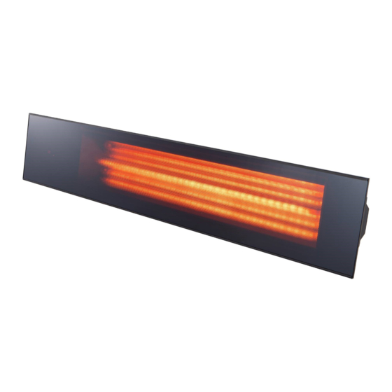
- Page 1 ® INSTALLATION MANUAL Glass Front Electric Radiant Heater Model Linea IP55...
-
Page 2: Table Of Contents
Content Important Introduction Specification Installation 4.1 Mounting 4.2 Mounting hole centres Heater Operation 5.1 Heater display/control pod 5.2 Remote control handset Maintenance 6.1 Remote control battery replacement 6.2 Replacing the lamp emitter 6.3 Handling a replacement emitter 6.4 Fitting a new lamp emitter 6.5 Recycling information Spare parts Wiring diagram... -
Page 3: Important
1. Important • Do not cover or obstruct the heater while it is in CAUTION! When using Spaceray electric heaters, basic use. precautions should always be followed to reduce the risk of fire, electric shock, and injury to persons, including the •... -
Page 4: Introduction
3.1 Dimensions 1002mm 4. Installation The Linea heater is fitted with 3m of supply cable and a 3-pin plug. For permenent connection it is unnecessary to open the terminal wiring enclosure, in order to carry out installation of this product. -
Page 5: Heater Operation
• CAUTION: When wall mounting the heater, do not NOTE: The brackets on the back of the heater can be CAUTION! NOTE: position the heater at an angle more than 90° or positioned to allow for narrow mounting surfaces such as less then 45°... -
Page 6: Maintenance
Standby - press to turn the heater (default is P1 after power off). P- - Press repeatedly to decrease the power level ofthe heater down to 30% (displays F1). T- - Press repeatedly to decrease the run back timer in 5 minute Increments Fig. -
Page 7: Recycling Information
Fig. J to reveal the bullet connectors at either end of 7. The lamp emitter should now be removed from the the lamp emitter wires (Fig. K). heater. Refit the new lamp emitter into the lamp emitter holders ensuring the ceramic caps are correctly seated. -
Page 8: Spare Parts
7. Spare parts Item Description Heater body Glass frame Side reflector Lamp emitter Body bracket Mounting bracket M8 Pozi screw for glass frame M4 Pozi screw for side reflector M8 Hex bolt for bracket M4 Pozi screw for body bracket M8 Nyloc nut M8 Plain washer M4 Spring washer for body bracket... -
Page 9: Wiring Diagram
8. Wiring Diagram 230V Rated lamp emitter Controller PCBA DPDT Switch 230V - 50Hz... - Page 11 NOTES...
- Page 12 ® Tel: +44(0)1473 830 551 Fax: +44(0)1473 832055 www.spaceray.co.uk info@spaceray.co.uk Gas Fired Products (UK) Ltd Chapel Lane Claydon Ipswich Suffolk, IP6 0JL FACTORIES: IPSWICH, ENGLAND - CHARLOTTE, N.C, U.S.A Linea Manual December 2022...
Need help?
Do you have a question about the Linea and is the answer not in the manual?
Questions and answers