Table of Contents
Advertisement
Quick Links
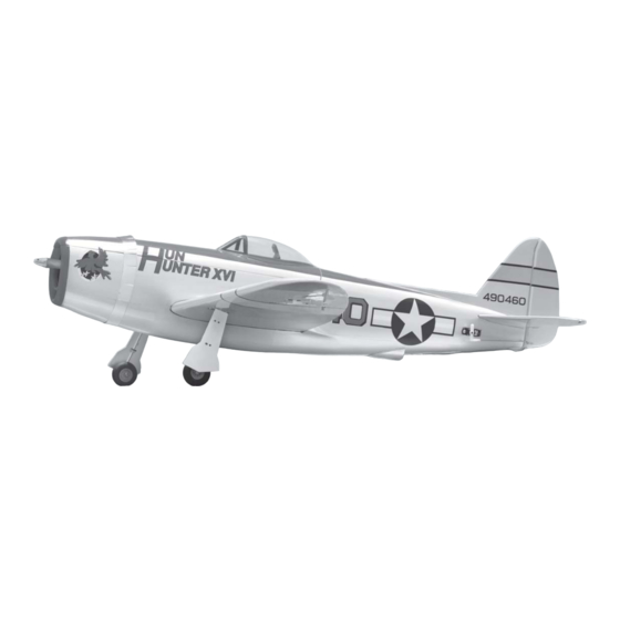
Instruction Manual book
SPECIFICATION
Wingspan : 1,050 mm
Length
Weight
Radio
Servo
Motor
Battery
Speed control : 40A.
Propeller
41.34 inches.
: 950mm
37.4 inches.
:
1 kg
2.2 lbs.
: 04 channels.
: 4 mini servos.
:
BL2215/20 EMAX
:
3 Cells-Li-Poly-
: 9 x 6.
V 2.250 mAh.
ITEM CODE:BH118.
Made in Vietnam.
Advertisement
Table of Contents

Subscribe to Our Youtube Channel
Related Manuals for Black Horse Model P- 47 THUNDERBOLT- EP


Summary of Contents for Black Horse Model P- 47 THUNDERBOLT- EP
- Page 1 Instruction Manual book ITEM CODE:BH118. SPECIFICATION Wingspan : 1,050 mm 41.34 inches. Length : 950mm 37.4 inches. Weight 1 kg 2.2 lbs. Radio : 04 channels.
-
Page 2: Parts List
Instruction Manual Item code: BH118 This instruction manual is designed to help you build a great flying aeroplane. Please read this P- 47 THUNDERBOLT- EP manual thoroughly before starting assembly of your . Use the parts listing below to identify all parts. -
Page 3: Safety Precaution
P-47 THUNDERBOLT-EP- Instruction Manual Item code: BH118 Caution: this model is not a toy! If you are a beginner to this type of powered model, please ask an experienced model flyer for help and support. If you attempt to operate the model without knowing what you are doing you could easily injure yourself or somebody else. -
Page 4: Installing The Aileron Servo
P-47 THUNDERBOLT-EP- Instruction Manual Item code: BH118 REPLACEMENT SMALL PARTS 3x 10mm. 3x 15 mm. 1.Door mounting wheel. Bottom side of left wing 2. Aluminium landing gear. 3. Plastic parts bottom fuselage. 4. Plastic strap Aileron. 5. Wheels. 6. Motor mount wood: Aileron. - Page 5 P-47 THUNDERBOLT-EP- Instruction Manual Item code: BH118 bottom side. C/A glue. Servo tray. C/A glue. Remove covering C/A glue. Servo tray. Top side. Servo C/A glue. Repeat the procedure for the other wing half. 2. Using a modeling knife, remove the cov- ering servo tray.
- Page 6 P-47 THUNDERBOLT-EP- Instruction Manual Item code: BH118 3. Using the thread as a guide and using 5. Instal servo tray with aileron servo into masking tape, tape the servo lead to the end the wing as same as picture below. of the thread: carefully pull the thread out.
-
Page 7: Installing Landing Gear
P-47 THUNDERBOLT-EP- Instruction Manual Item code: BH118 Bottom side. A+B Epoxy PLUS glue Repeat the procedure for the other wing half. INSTALLING LANDING GEAR. See pictures below: A+B Epoxy PLUS Glue. Control horn of the aileron. 3.INSTALLING THE AILERON LINKAGES. Installing the aileron linkages as pictures below. - Page 8 P-47 THUNDERBOLT-EP- Instruction Manual Item code: BH118 2 x12mm Secure. Secure.
- Page 9 P-47 THUNDERBOLT-EP- Instruction Manual Item code: BH118 C/A glue Bottom side. P l a s t i c strap Repeat the procedure for the other gear. INSTALLING ELECTRIC MOTOR. See pictures below: Plastic strap C/A glue Motor mount wood: 3x 15mm...
- Page 10 P-47 THUNDERBOLT-EP- Instruction Manual Item code: BH118 3x 15mm Epoxy glue. Secure. C/A glue. Secure.
-
Page 11: Installing The Elevator Servo
P-47 THUNDERBOLT-EP- Instruction Manual Item code: BH118 Front view. INSTALLING THE ELEVATOR SERVO. 1. Install the rubber grommets and brass collets into the elevator servo. Test fit the servo into the servo tray. 2. Mount the servo to the tray using the mounting screws provided with your radio system. - Page 12 P-47 THUNDERBOLT-EP- Instruction Manual Item code: BH118 Epoxy glue Epoxy glue Epoxy glue C/A glue. Epoxy glue...
-
Page 13: Elevator Control Horn Installation
P-47 THUNDERBOLT-EP- Instruction Manual Item code: BH118 hinge Bottom side. ELEVATOR CONTROL HORN INSTALLATION. Elevator control horn install as same as the way of aileron control horn. Please see pic- tures below. Control horn of elevator. C/A glue. A+B Epoxy PLUS Glue. -
Page 14: Vertical Stabilizer Installation
P-47 THUNDERBOLT-EP- Instruction Manual Item code: BH118 ELEVATOR PUSHROD INSTALLATION. Elevator pushrod install as same as the way of aileron pushrod. 105 mm elevator pushrod wire Left side. Elevator pushrod Bottom side. hinge Top side. Push VERTICAL STABILIZER INSTALLATION. See picture below: C/A glue... -
Page 15: Rudder Pushrod Installation
P-47 THUNDERBOLT-EP- Instruction Manual Item code: BH118 C/A glue A+B Epoxy PLUS Glue. Rudder control horn RUDDER PUSHROD INSTALLATION. Rudder pushrod install as same as the way of aileron pushrod. 105 mm Rudder pushrod. Top side. RUDDER CONTROL HORN INSTALLA- TION. - Page 16 P-47 THUNDERBOLT-EP- Instruction Manual Item code: BH118 Do not permanently secure the re- ceiver and battery until after balancing the model. 4) Using a 2mm drill bit, drill a hole through the side of the fuselage, near the receiver, for the antenna to exit.
-
Page 17: Wing Attachment
P-47 THUNDERBOLT-EP- Instruction Manual Item code: BH118 Receiver WING ATTACHMENT. Locate the aluminium wing dihedral brace. aluminium 9mm wing dihedral brace. 222 mm *** Test fit the aluminium tube dihedral brace into each wing haft. The brace should slide in easily. - Page 18 P-47 THUNDERBOLT-EP- Instruction Manual Item code: BH118 Accurately mark the balance point on the top of the wing on both sides of the fuselage. The balance point is located 63mm back from the leading edge. This is the balance point at which your model should balance for your first flights.
-
Page 19: Control Throws
P-47 THUNDERBOLT-EP- Instruction Manual Item code: BH118 CONTROL THROWS. PRE-FLIGHT CHECK. 1. We highly recommend setting up a plane 1. Completely charge your transmitter and using the control throws listed. receiver batteries before your first day of fly- ing.
Need help?
Do you have a question about the P- 47 THUNDERBOLT- EP and is the answer not in the manual?
Questions and answers