Side-Power SR80/185T Installation & User Manual
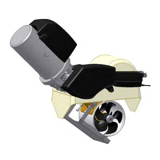
Retractable thruster assembly
Hide thumbs
Also See for SR80/185T:
- Installation & user manual (24 pages) ,
- Installation & user manual (29 pages)
Table of Contents
Advertisement
SIDE-
SIDE-
SIDE-POWER
®
Thruster Systems
POWER
POWER
Thruster systems
Installation & User Guide
GB
Installation and user manual
Installasjons- og brukerveiledning
N
SLEIPNER MOTOR AS
P.O. Box 519
N-1612 Fredrikstad
Norway
Tel:
Fax:
Retractable thruster assembly
SLEIPNER MOTOR AS
P.O. Box 519
N-1612 Fredrikstad
Norway
Tel: +47 69 30 00 60
Fax: +47 69 30 00 70
+47 69 30 00 60
+47 69 30 00 70
SR 80/185 T
SX80/185T & SX100/185T
SR80/185T & SR100/185T
External sternthruster
SR 100/185 T
w w w . s i d e - p o w e r . c o m
s i d e p o w e r @ s l e i p n e r. n o
w w w . s i d e - p o w e r . c o m
s i d e p o w e r @ s l e i p n e r. n o
© Sleipner Motor AS version 1.1 - 2010
assembly
© Sleipner Motor AS 20
Advertisement
Table of Contents

Related Manuals for Side-Power SR80/185T


Summary of Contents for Side-Power SR80/185T
- Page 1 SIDE-POWER ® here the inside SR 80/185 T Thruster Systems r installation SX80/185T & SX100/185T POWER POWER SR80/185T & SR100/185T huster assembly External sternthruster SR 100/185 T assembly ls enables good Retractable thruster assembly Thruster systems ve legs which Installation & User Guide...
-
Page 2: Table Of Contents
Contents Installation instructions User’s manual Measurements, thruster..............3 General use & alarm indications ..........17 Technical specifications ..............4 Installation checklist..............18 Important user precautions ............19 Thruster installation Positioning of the thruster unit ...........5 Troubleshooting ............... 20 Hatch cut out ................6 Warranty statement .............. 22 Fitting the hatch ................ -
Page 3: Measurements, Thruster
SR100/185T SR80/185T - SR100/185T 1. .0 - 20 ... -
Page 4: Technical Specifications
”heng” på relé, eller signal is continous for more than 3 minutes om trøsteren går kontinuerlig i 3 minutter. SR80/185T - SR100/185T 1. .0 - 20... -
Page 5: Positioning Of The Thruster Unit
4. Position unit to center marks and longitudinal guidelines/marks. 4. Plasser enhet tilbake på sentermerker, og mot hjelpelinjen/punktet i lengderetningen. SR80/185T - SR100/185T 1. .0 - 20... -
Page 6: Hatch Cut Out
Når du har kuttet ferdig skal du ha en pen luke med et tilhørende pent for thickness of cut. hull. Forsegl kantene på luke og skrog med epoxy og glassfibercutting for å fylle igjen tykkelsen etter kuttet. SR80/185T - SR100/185T 1. .0 - 20... -
Page 7: Fitting The Hatch
Dette for å unngå at det renner epoxy inn i enheten og limer igjen luke til skrog. SR80/185T - SR100/185T 1. .0 - 20... -
Page 8: Moulding
Enheten lamineres fast grundig på innsiden av skroget, og på utsiden av skroget og inn i kassen. Ref illustration ”Profile, molding 1-3”. Se illustrasjon ”Profil laminering 1-3”. SR80/185T - SR100/185T 1. .0 - 20... -
Page 9: Fitting The Electromotor
Dekket må fjernes før motoren tas i bruk. tor and the solenoids. This cover must be removed before the thruster is being used. SR80/185T - SR100/185T 1. .0 - 20... -
Page 10: Electrical Installation
(A1) terminal on the motor. If you feel unsure on how to perform this check, contact skilled personnel for guidance. SR80/185T - SR100/185T 1. .0 - 20... -
Page 11: Maintenance
• All electrical connections are clean and fastened firmly. • Make sure that your batteries are in a good condition so that the thruster gets a good voltage. Old or bad batteries will give a reduced performance from the thruster. SR80/185T - SR100/185T 1. .0 - 20... -
Page 12: Measurements, Hatch
Measurements, hatch Målskisse, luke Measurements, outside - gelcoat side Measurements, inside Inner cut line SR80/185T - SR100/185T 1. 0 - 20 ... -
Page 13: Template, Holes In Hatch
• Make sure that your batteries are in a good condition so that the thruster gets a good voltage. Old or bad batteries will give a reduced performance from the thruster. SR80/185T - SR100/185T SR80/185T - SR100/185T 1.0.0 - 2009... -
Page 14: S-Link Installation System Overview
Må benyttes i hver ende av backbone- “loop” Must be one in each end ”hovedsløyfen” Part #: 6 1327 Part #: 6 1327 Art. nr: 6 1327 of the backbone ”loop” Part #: 6 1327 SR80/185T - SR100/185T 1. .0 - 20... -
Page 15: Planning & Precautions
å beskytte de åpne future additional equipment), make sure to protect open connectors from kontaktene fra fukt for å forhindre korrosjon i kontakten. water and moisture to avoid corrosion in connector . SR80/185T - SR100/185T 1. .0 - 20... -
Page 16: System Schematics
Ledningen som kobles til batteriets plusspol må sikres med en 5A sikring W / Automatic Main Switch Draw no: The battery pos. must be connected through a 5A fuse. Norway RTS-A00-651-01 Tel: +47 69 30 00 60 SR80/185T - SR100/185T 1. .0 - 20... -
Page 17: General Use & Alarm Indications
SPEED. THIS WILL TRIGGER THE “Retract operation obstructed” ALARM. HVIS ALARM UTLØSES, REDUSER FARTEN OG TRYKK BEGGE ”ON” KNAPPENE FØRST FØR ”OFF” TRYKKES PÅ NYTT. IF ALARM IS TRIGGERED, REDUCE SPEED AND PRESS BOTH “ON” BUTTONS BEFORE RETRYING “OFF” BUTTON SR80/185T - SR100/185T 1. .0 - 20... -
Page 18: Installation Checklist
Skottet hvor thrusteren er montert er isolert fra kjølvann og har ingen åpenbar risiko for lekkasje. Other comments by installer: Kommentar fra installør: SR80/185T - SR100/185T 1. .0 - 20... -
Page 19: Important User Precautions
• Never store anything (e.g. equipment, sails, ropes etc.) in the same compartment as the thruster. When the thruster runs for a longer period it will get hot and will cause damage. SR80/185T - SR100/185T 1. 0 - 20... -
Page 20: Troubleshooting
Solenoid lock-in, auto stop of thruster, auto retry every 10 Shut off thruster main switch, tap slightly on the solenoid to see if it will release. Turn on thruster main switch. If solenoid is still in lock-in mode, replace solenoid. seconds. SR80/185T - SR100/185T 1. .0 - 20... -
Page 21: Problemer Og Løsninger
10 sekund for å se om feilen å se om kontaktflatene slipper. Slå på hovedstrømbryter og se om feilen er fikset. Om er rettet. den vedvarer må relé byttes. SR80/185T - SR100/185T 1. .0 - 20... -
Page 22: Warranty Statement
8. The Warrantor assumes no liability for incidental or consequential damages of any kind including damages arising from collision with other vessels or objects. 9. This warranty gives you specific legal rights, and you may also have other rights which vary from country to country. SR80/185T - SR100/185T 1. .0 - 20... -
Page 23: Spareparts List & Drawing
Partslist, SR80/185T & SR100/185T SP 75 Ti SR80/185T - SR100/185T 1. .0 - 20 SP 75 Ti / SP 95 Ti / SP 125 Ti 2.5.1- 2007... -
Page 24: Service Centres
Fax: +44 1364 649 399 www.imtra.com Fax: +385 51 704 600 andy@sleipner.co.uk side-power@imtra.com acyachting@gmail.com Sleipner Motor AS • P. O. Box 519, N-1612 Fredrikstad • Norway Tel: +47 69 30 00 60 • Fax: +47 69 30 00 70 • sidepower@sleipner.no • www.side-power.com...
Need help?
Do you have a question about the SR80/185T and is the answer not in the manual?
Questions and answers