
Related Manuals for Videx VK4K/6256 Series


Summary of Contents for Videx VK4K/6256 Series
- Page 1 VIDEOKIT VK4K/6256 SERIES “6 Wire” bus one way, two way videokit VK4K R04A VK4KX R04A VK4KC Rev.0.5 6256 Installation handbook We recommend 66250457-EN - V5.1 - 31/08/20 This equipment is installed by a Competent Electrician, Security or Communications Engineer.
-
Page 2: Table Of Contents
This manual has been written and revised carefully. The instructions and the descriptions which are included in it are referred to VIDEX parts and are correct at the time of print. However, subsequent VIDEX parts and manuals, can be subject to changes without notice. -
Page 3: System Components And Available Versions
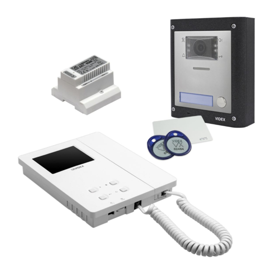
VK4K/6256 Series “6 wire Bus” videokit System components and available versions VK4K/6256 Colour videokit. OUTDOOR INDOOR STATION STATION Videophone 135,0 45,0 22,7 Art. 6256 pag. 20 Camera unit Art. 4833 pag. 8 ACCESSORIES Power supply 15,7 Art. 850K 43,8 pag. 5 120,0 Flush... - Page 4 VK4K/6256 Series “6 wire Bus” videokit System components and available versions VK4KX/6256 Colour videokit with embended proximity key reader. INDOOR OUTDOOR STATION STATION Videophone 135,0 45,0 22,7 Art. 6256 pag. 20 Camera unit Art. 4833X pag. 8 ACCESSORIES Power supply Art. 850K pag. 5...
- Page 5 VK4K/6256 Series “6 wire Bus” videokit System components and available versions VK4KC/6256 Colour videokit plus a codelock module. OUTDOOR INDOOR STATION STATION 135,0 45,0 22,7 Videophone Art. 6256 pag. 20 Camera unit Art. 4833 pag. 8 ACCESSORIES Codelock Power supply module Art. 850K Art. 4901...
-
Page 6: General Directions For Installation
VK4K/6256 Series “6 wire Bus” videokit General directions for installation CONNECTION TO MAINS The system must be installed according to national rules in force, in particular we recommend to: • Connect the system to the mains through an all-pole circuit breaker which shall have contact separation of at least 3mm in each pole and shall disconnect all poles simultaneously;... -
Page 7: Troubleshooting Guide
VK4K/6256 Series “6 wire Bus” videokit Troubleshooting guide In case of system failure, try the following preliminary checks: • Check that the cables are connected as shown in the installation diagram and that the cables are firmly fixed into the relevant terminals;... - Page 8 VK4K/6256 Series “6 wire Bus” videokit Art. 4833/4833X Speaker unit R04A R03A Made in Italy J2 J3 J4 STEEL 4833-1 UNIT ID RELAY TIME 4833-2 1..4 CONV.TIME HIGH BRASS 4833X-1 4833X-2 Fig. 1 Front Fig. 2 Back DESCRIPTION LEGEND Speaker unit module comprising of high quality auto iris colour Camera with illumination LEDs camera with white light illumination LEDs.
- Page 9 VK4K/6256 Series “6 wire Bus” videokit Art. 4833/4833X Speaker unit SETTINGS 4 WAY DIP-SWITCH First two switches are used to set the speaker unit address: the speaker unit address is required for camera recall operation on 2 or more entrance systems.
-
Page 10: Art. 4833/4833X Speaker Unit
VK4K/6256 Series “6 wire Bus” videokit Art. 4833/4833X Speaker unit PROGRAMMING TAGS (ONLY FOR ART. 4833X) MASTER CARD The module is supplied with a master card. The master card is preprogrammed in the factory. The card is used to add and delete user access tags. - Page 11 VK4K/6256 Series “6 wire Bus” videokit Art. 4833/4833X Speaker unit 1. Place the master card in front of the tag reader. The module emits one high-pitched “beep” sound and the LED illuminates. 2. Press and hold the call button (the lower call button in the case of an external 2-button module).
- Page 12 VK4K/6256 Series “6 wire Bus” videokit Art. 4833/4833X Speaker unit HOW TO CONNECT ELECTRIC LOCK The “door-open” relay can operate either as “dry contact” or “capacitive discharge” mode. • In “dry contact” operation mode the relay works in a traditional way, a power supply or a power source is needed to operate the lock (12-24Vac/dc 2A max), and activation lasts according to the door opening time programmed.
- Page 13 VK4K/6256 Series “6 wire Bus” videokit Art. 4833/4833X Speaker unit CAMERA NOTES FIELDS OF VIEW MAXIMUM ILLUMINATION DISTANCE The fields of view for standard camera are 55° for vertical angle and 115° for horizontal angle FROM CAMERA AT NIGHT while for Wide Angle camera are 80° for vertical angle and 170° for horizontal angle.
- Page 14 GENERAL DIRECTIONS FOR INSTALLATION In order to achieve the best results from the schematics described it is necessary to install only original VIDEX equipment, strictly keeping to the items indicated on each schematic and follow these General Directions for Installation: •...
-
Page 15: Art. 4901 Digital Codelock Module
VK4K/6256 Series “6 wire Bus” videokit Art. 4901 Digital codelock module LOCK RELEASE BACK EMF PROTECTION A varistor must be fitted across the ter- VARISTOR (MOV) DIODE 1N4002 minals on AC lock release (Fig. 5) and a diode must be fitted across the ter- minals on a DC lock release (Fig. - Page 16 VK4K/6256 Series “6 wire Bus” videokit Art. 4901 Digital codelock module PROGRAMMING • Enter the ENGINEER’S CODE: first time type six times 1 (111111 First time six times ENTER THE factory preset) and press ENTER (The red LED will illuminate); 1 “111111” factory "ENGINEER’S CODE"...
- Page 17 VK4K/6256 Series “6 wire Bus” videokit Art. 4901 Digital codelock module CONNECTION TERMINALS SIGNALS CLEANING OF THE PLATE Use a clean and soft cloth. Use moderate warm water or non-ag- SW2 Relay 2 command signal (active low) gressive cleansers. SW1 Relay 1 command signal (active low)
- Page 18 VK4K/6256 Series “6 wire Bus” videokit 4000 Series Surface and flush mounting door station installation EXAMPLE: INSTALLING A FOUR MODULE OUTDOOR STATION fig. 1 fig. 2 fig. 3 fig. 4 fig. 5 fig. 6 fig. 7 fig. 8 fig. 9 fig.
- Page 19 VK4K/6256 Series “6 wire Bus” videokit 4000 Series Surface and flush mounting door station installation INSTALLING A SURFACE MOUNT DOOR STATION 1. Place the surface box against the wall (165-170cm between the top of the box and the floor level as shown in Fig. 1) and mark the fixing holes for the wall plugs and the hole for the cables (fig. 2).
- Page 20 VK4K/6256 Series “6 wire Bus” videokit Art. 6256 3.5" colour videophone 27 mm 144 mm PT3 PT2 Fig. 1 Fig. 2 DESCRIPTION LEGEND Surface mount videophone incorporating a 3.5” Hi-Res full Connection terminals colour active matrix LCD monitor specific for “6 wire” videokit 8 Way dip switch bank (VK4K, VRVK and VK8K range).
-
Page 21: Art. 6256 3.5" Colour Videophone
VK4K/6256 Series “6 wire Bus” videokit Art. 6256 3.5" colour videophone LEDS CONTROLS Call tone volume switch Door open LED (3 levels). Can be used to indicate the status of a door or gate. It re- Brightness control quires a switched 12Vdc connection to terminal “LD”. - Page 22 VK4K/6256 Series “6 wire Bus” videokit 6200 Series Videophone wall mounting instructions Fig. 1 Fig. 2 Fig. 3 Fig. 5 Fig. 4 Fig. 6 Fig. 7 1. In order to install the videophone, it is necessary to remove the cover, which contains all the electronics, from the base: firstly disconnect the handset from the videophone (by removing its plug from the videophone) then insert a 5.5mm flat screw driv-...
- Page 23 VK4K/6256 Series “6 wire Bus” videokit Art. 316 - Art. 316N 4 Way video distributor for system with balanced video signal DESCRIPTION ART. 316 4 Way video distributor for systems with balanced video signal. In white plastic ABS box 11x70x30mm surface mount. ART. 316N As Art.
- Page 24 - 24 - 66250457-EN - V5.1 - 31/08/20...
- Page 25 - 25 - 66250457-EN - V5.1 - 31/08/20...
- Page 26 - 26 - 66250457-EN - V5.1 - 31/08/20...
- Page 27 - 27 - 66250457-EN - V5.1 - 31/08/20...
- Page 28 - 28 - 66250457-EN - V5.1 - 31/08/20...
- Page 29 - 29 - 66250457-EN - V5.1 - 31/08/20...
- Page 30 - 30 - 66250457-EN - V5.1 - 31/08/20...
- Page 31 - 31 - 66250457-EN - V5.1 - 31/08/20...
- Page 32 - 32 - 66250457-EN - V5.1 - 31/08/20...
- Page 33 - 33 - 66250457-EN - V5.1 - 31/08/20...
- Page 34 - 34 - 66250457-EN - V5.1 - 31/08/20...
- Page 35 DISPOSAL In accordance with the Legislative Decree no. 49 of 14 March 2014 “Implementation of the Directive 2012/19/EU on waste electrical and electronic equipment (WEEE)”. The crossed-out bin symbol on the equipment or on the packaging indicates that when the product reaches the end of its lifetime, it must be collected separately from mixed municipal waste.
- Page 36 MANUFACTURER VIDEX ELECTRONICS S.P.A. FABBRICANTE Via del Lavoro, 1 FABRICANT 63846 Monte Giberto (FM) Italy FABRICANTE Tel (+39) 0734 631669 FABRIKANT Fax (+39) 0734 632475 www.videx.it - info@videx.it CUSTOMER SUPPORT VIDEX ELECTRONICS S.P.A. UK Customers only: SUPPORTO CLIENTI www.videx.it - technical@videx.it...
Need help?
Do you have a question about the VK4K/6256 Series and is the answer not in the manual?
Questions and answers