Table of Contents
Advertisement
Quick Links
Advertisement
Table of Contents

Related Manuals for CTC Union FRM220A-GSW/SNMP


Summary of Contents for CTC Union FRM220A-GSW/SNMP
- Page 1 FRM220A-GSW/SNMP Gigabit Switch / SNMP Controller...
- Page 3 Gigabit Switch / SNMP Card Ethernet Aggregate Rack, 20 Slot, 2U Version 1.0 September 9, 2011 (Release) Version 1.01 September 26, 2011 (update) Copyright © 2010-2011, CTC Union Technologies, Inc. All rights reserved. All specifications are subject to change without prior notice.
- Page 4 CTC Union Technologies assumes no responsibility, however, for possible errors or omissions, or for any consequences resulting from the use of the information contained herein. CTC Union Technologies reserves the right to make changes in its products or product specifications with the intent to improve function or design at any time and without notice and is not required to update this documentation to reflect such changes.
-
Page 5: Table Of Contents
Table of Contents Chapter 1 Introduction.................................. 7 1.0 Introduction..................................7 1.1 Brief Functional Description..............................7 1.2 Card Options ..................................7 1.3 System Block Diagram ................................ 7 1.4 Chassis Front Description ..............................8 1.5 Chassis Rear Description ..............................8 ... - Page 6 Table of Contents...
-
Page 7: Chapter 1 Introduction
Gigabit Ethernet switch, proceed to Chapter 2. This manual is used to explain the configuration of the FRM220A-GSW/SNMP (Gigabit Switch / SNMP Controller) and operating procedures. This manual is divided into 4 Sections, the Introduction, Provisioning, Web Based Management and Trouble Shooting, plus the Appendices. -
Page 8: Chassis Front Description
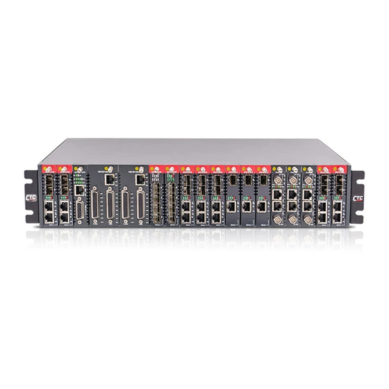
Chapter 1 Introduction 1.4 Chassis Front Description The front of FRM220A contains the line card slots. They are numbered 1 through 20, from left to right as viewed from the front. The typical configuration is with one GSW/SNMP (Network Management Controller) card in rear slot and manageable line cards in any front slot numbered 1 through 20. -
Page 9: Chassis Specifications
Chapter 1 Introduction 1.6 Chassis Specifications Environment Temperature -10 - 50°C (14-122°F) Humidity 5-95% non condensing Alarm relay contact ratings 125VAC 110VDC 0.6A 30VDC Power Module Specifications AC Power Module Input : Universal, 100~240VAC ±10% at ambient temperature; Frequency : 47~63 Hz Output : DC 12V, 200W maximum rating (Green power rated, 89% power efficiency) Connector : C14 (IEC 60320-1) DC Power Module... -
Page 10: Gsw/Snmp (Aggregate Switch)
Screw in the holding screws and just barely tighten (do NOT over tighten). The card will not come out on its own; it will require significant pulling force to unseat. FRM220A-GSW/SNMP Installation Slot Link Status LED Array... -
Page 11: Frm220A Fault Handling
Chapter 1 Introduction 1.9 FRM220A Fault Handling The FRM220A management is designed is such a way as to minimize any disruption to normal traffic in the event of any single component failure and to allow rapid recovery of full operations through replacement of FRUs (Field Replaceable Units). -
Page 12: Frm220A Application
Chapter 1 Introduction 1.10 FRM220A Application The FRM220 is an excellent choice for complimenting fiber infrastructure in Metro LAN, campus, corporate buildings, factories, or in FTTx applications. It can also be deployed in a mobile backhaul application for packet transport. With standard SNMP management, carriers or Internet Service Providers will have confidence to deploy a solution that provides the necessary remote monitoring and configuration features. -
Page 13: Chapter 2 Telnet Provisioning
'save' operations. Management via TCP/IP also includes using a web browser or any network management software after compiling the enterprise MIB-II compliant file for FRM220A-GSW/SNMP. A MIB browser provides another simple platform for the user to setup using the SNMP protocol remotely. -
Page 14: Telnet Login
To enter "Telnet mode", a user ID (default is admin) is required and a password may be required. By default, there is no password set from the factory. The user password provides security to protect the system. CTC UNION TECHNOLOGIES CO., LTD. FRM220A-GSW/SNMP VER.[1.021]... -
Page 15: Tcp/Ip Configuration
The community string must be set. d. The SNMP card's subnet mask can be set. Step One: Agent Configuration Process Telnet into the GSW/SNMP, use the ID ‘admin’ with no password. CTC UNION TECHNOLOGIES CO., LTD. FRM220A-GSW/SNMP VER.[1.021] ===============================================================================... - Page 16 Chapter 2 Provisioning From the System Status and Configuration menu, type ‘2’, System Configuration. << System Configuration >> <1> :System Contact <2> :System Name <3> :System Location <4> :DHCP Client [Disable] <5> :DHCP Renew [192.168.1.1] <6> :IP Address [192.168.1.1] These are the default TCP/IP settings. <7>...
- Page 17 IP network. The system provides a Telnet server feature that allows login over TCP/IP networks and provides a text based menu display. The FRM220A-GSW/SNMP is supplied with an enterprise MIB file (Management Information Base) that can be compiled into any standard SNMP network management software. The MIB file complies with MIB-II and ANS.1 standards.
-
Page 18: Chassis Information And Alarm Setup
Power, Fans, and UTP or Fiber link and Far End Fault states for local and remote converters. From the System Status and Configuration menu of the FRM220A, press the '4' (four) key to enter the Alarm Status and Configuration. CTC UNION TECHNOLOGIES CO., LTD. FRM220A-GSW/SNMP VER.[1.025] ===============================================================================... - Page 19 Chapter 2 Provisioning For an example of configuration for Alarm #2, press '2' (two). Set Alarm 2 Mode. <0> Disable <1> By Fan <2> By Define 1 <3> By Define 2 <ESC>:Previous Menu. 0 : This will completely disable Alarm #2. 1 : This is the factory default setting.
-
Page 20: User Password Setup
TFTP server is required. Please refer to Chapter 3. Note: When CTC Union releases an update, a 'package' will be generated that includes all required code, the TFTP server application, a detailed upgrade procedure in PDF format specifically for the release and a release notice listing the fixes or added features of the firmware. -
Page 21: Chapter 3 Web Based Management
Note: CTC Union has an online demo unit placed on a public IP and answerable by DNS. We hope this demo will help our resellers to promote our product. End users may also find that evaluating our unit could lead to a decision to purchase our product. -
Page 22: Alias Configuration
Chapter 3 Web Based Management 3.2.2.2 Home Page The Web GUI behaves just like any other web based application. The following graphic shows all of the areas that may be clicked for further configuration. Slots without any line card or without manageable line card will be shown as 'Empty'. -
Page 23: Snmp Configuration
Chapter 3 Web Based Management 3.2.4 SNMP Configuration Clicking on the "SNMP Configuration" item will display an overview screen that allows setting the SNMP system information, including enabling the mode, selecting SNMP version, setting up trap management and configuring community strings. 3.2.5 Local/Remote Area "Local Area"... -
Page 24: System
Chapter 3 Web Based Management 3.2.6 System The system settings include informational as well as configuration setting. Each item will be explained below briefly. 3.2.6.1 Information Information about the system is displayed here, including the hardware version, the MAC address, firmware versions and software version information. - Page 25 Chapter 3 Web Based Management 3.2.6.5 Password Setup Enter the old password, if there is one, and enter new password twice. Click “Save”. 3.2.6.6 Monitor The Monitor screen will display system information for the type and status of Power 1 and Power 2, the fans status and RPM, the GSW CPU temperature and the GSW card board temperature (in Centigrade).
- Page 26 Chapter 3 Web Based Management 3.2.6.9 Event Log The event log keeps a running record of events that happen in the FRM220A- GSW/SNMP, including cards inserted/removed, card faults, power or fan faults, and remote login/logouts. The “Clear All” button will remove all log entries.
-
Page 27: Switch
Chapter 3 Web Based Management 3.2.6.14 Reset All Line Cards The reset all line cards function will do a warm reboot of all line cards installed and recognized in the 220A. To reset the cards, the “Yes” button must be clicked. 3.2.6.15 All Line Cards Set to Factory Default The set all line cards to factory default function will return each installed... - Page 28 Chapter 3 Web Based Management 3.2.7.3 Traffic The ‘Traffic’ tab will display the RMON traffic counters for each port. The counters show transmitted and received packet count, transmitted and received byte count as well as error packets, dropped packets and filtered packets for each port.
-
Page 29: Ports Aggregation
Chapter 3 Web Based Management 3.2.8 Ports Aggregation There are 8 (eight) aggregation groups that can be assigned any of the 28 available ports. A port can only be assigned to one group. 3.2.9 Ports VLAN... - Page 30 Chapter 3 Web Based Management This page left blank intentionally.
-
Page 31: Chapter 4 Troubleshooting
Chapter 4 Troubleshooting Chapter 4 Troubleshooting 4.1 Network Settings 4.1.1 Review TCP/IP Settings During unit startup, the LED ‘Matrix’ will flash as the switch boots up, and then any slots with cards or any of the 4+4 SFP/Copper ports with n Ethernet link will light during normal operation. Refer to Chapter 2 section 2.2.5 TCP/IP Configuration for the SNMP agent settings. -
Page 32: Review Manager Settings
Chapter 4 Troubleshooting 4.1.2 Review Manager Settings For SNMP management software to connect to the GSW for management, the GSW/SNMP must be properly configured with the manager's IP address and authorized for read/write (via community string setting) and trap messages. Review the settings explained in 2.2.5 TCP/IP Configuration. If the management workstation is on a remote network, ensure it can also pass the ping test. -
Page 33: Appendix A. Frm220A Cards Options
Appendix A Appendix A. FRM220A Cards Options A.0 Introduction The FRM220A In-Band Managed Media Converter Chassis is designed to accept a variety of optical to electrical or optical to optical converter cards. As cards are added, this section will be updated with the relevant information for the new cards. -
Page 34: Web Management
Appendix A Specifications G.703 Interface Connector HDB26 Female with adapters for 75 or 120 Ohm Data rate 2048kb/s Impedance 75 ohm for unbalanced, 120 ohm for balanced Framing Requires Unframed, transparent clear channel E1s RxSensitivity -43dB (extra Long Haul) TxPulseAmp. 3.00V p-p (120 ohm); 2.73V p-p (75 ohm) Line code HDB3 Indications... - Page 35 Appendix A The “LAN port” supports auto-negotiation or forced mode setting. If force mode setting the card, be sure to properly configure the GSW port for the same forced mode. Additionally, the LAN port supports enabling flow control, bandwidth control and can be made VLAN tag aware. The “Device”...
- Page 36 Appendix A The iMUX has an integral “BERT” function to performance test any one of the E1 lines, one at a time. Enable the function, select the E1 line and click “Save”. The BERT function also requires that the remote unit have its E1 placed in loop back. So, go to the remote unit and place the E1 (E1-5 in this example) into RLB.
-
Page 37: Frm220A-E1/Data Dsu/Csu Converter Card
Appendix A A.2 FRM220A-E1/Data DSU/CSU Converter Card The FRM220A-E1/Data is a single port G.703/704 Fractional E1 DSU/CSU card for the FRM220/220A Series Platform Media Converter Rack. The converter supports Unframed, PCM31, PCM31+CRC4, PCM30, and PCM30+CRC4 framing modes. The clock source may be selected internally, recovered from received E1 signal, externally from the Data port or transparent. -
Page 38: Web Management
Appendix A A.2.1 Web Management The “E1 Port” tab displays status and information and also sets up the framing and timeslot assignment. The frame mode can be framed or unframed (clear channel). Framed mode supports either CCS (PCM31) or CAS (PCM30) framing. - Page 39 Appendix A When the E1/DATA is ordered with a V.35 interface, the unit comes with a HDB26 male to MB34 Female adapter cable, 1 meter long. The pin assignment follows the table below. Abbreviation HDB26 MB34 V.35 PIN# PIN# Circuit ↔...
- Page 40 Appendix A When the E1/DATA is ordered with a RS-530 interface, the unit comes with a HDB26 male to DB25 Female adapter cable, 1 meter long. The pin assignment follows the table below. Abbreviation HDB26 DB25 RS-530 PIN# PIN# Circuit ↔...
- Page 41 Appendix A When the E1/DATA is ordered with a RS-449 interface, the unit comes with a HDB26 male to DB37 Female adapter cable, 1 meter long. The pin assignment follows the table below. Abbreviation HDB26 DB37 RS-449 PIN# PIN# Circuit ↔...
- Page 42 Appendix A When the E1/DATA is ordered with a X.21 interface, the unit comes with a HDB26 male to DB15 Female adapter cable, 1 meter long. The pin assignment follows the table below. Abbreviation HDB26 DB15 X.21 PIN# PIN# Circuit ↔...
-
Page 43: Frm220A-Eoe1 Ethernet Over E1 Converter
Appendix A A.3 FRM220A-Eoe1 Ethernet over E1 Converter The FRM220A-Eoe1 is a single port G.703/704 Fractional E1 DSU/CSU card with built-in HDLC Bridge for the FRM220/220A Series Platform Media Converter Rack. The converter supports Unframed, PCM31, and PCM30 framing modes. The clock source may be selected internally or recovered from received E1 signal. The Ethernet port utilizes a single RJ-45 connector. -
Page 44: Web Management
Appendix A A.3.1 Web Management Eoe1 “E1 Port” tab contains the status and E1 parameter settings. The status fields will report Signal normal or LOS, E1 sync or NoSync, Alarm Indication Signal active or not, Bit errors if running integral BERT, code violations, Loss of Multi-Frame and remote power condition (dying gasp). -
Page 45: Frm220A-1000Eas/X In-Band (802.3Ah) Managed Fiber Gigabit Media Converter
Appendix A A.4 FRM220A-1000EAS/X In-band (802.3ah) Managed Fiber Gigabit Media Converter 1000EAS/X is an IEEE802.3ah OAM/IP compliant in-band managed optical fiber media switch/converter for 10/100/1000Base-TX Ethernet and 1000Base-SX/LX gigabit fiber that also provides NMS functions for Link-Loss- Forwarding, Remote-Monitoring-Status, bandwidth control and Loop-Back-Test. When auto-negotiation is selected, these units will automatically tailor themselves to convert 10, 100, 1000 full or half duplex, depending on your specific network needs. -
Page 46: Functional Details
Appendix A A.4.1 Functional Details Ethernet The 1000EAS/X is based on a L2 switch chip which supports non-blocking switching fabric with up to 1024 MAC lookup filtering table and support for Egress tagging/untagging selectable per port in any combination using 802.1Q VLAN support for 4094 VIDs and BPDU handling for spanning tree protocol. - Page 47 Appendix A...
- Page 48 Appendix A 3. Fault condition sent via OAM to far end 2. FX Link Down 4. FEF Led Lit Local Rx fiber Broken fiber local 1. fiber remote broken Remote Power 3. FEF LED lit 1. MC powered OFF Failure fiber local 2.
-
Page 49: Block Diagram Of 1000Eas/X
Appendix A A.4.2 Block Diagram of 1000EAS/X 12VDC Reg. μP LEDs RS485 driver SerDes SerDes Switch 10/100/1000M 10/100/1000M (For reference only) A.4.3 1000EAS/X Stand-alone Telnet Configuration Because the FRM220A-1000EAS/X has its own comprehensive user manual, this manual will not go into the detailed configuration of this device.
Need help?
Do you have a question about the FRM220A-GSW/SNMP and is the answer not in the manual?
Questions and answers