Table of Contents
Advertisement
Quick Links
Advertisement
Table of Contents

Related Manuals for CTC Union GSW-3208M2


Summary of Contents for CTC Union GSW-3208M2
- Page 1 GSW-3208M2 Managed Gigabit Ethernet Switch...
- Page 2 CTC Union Technologies makes no warranty, representation, or guarantee regarding the suitability of its products for any particular purpose, nor does CTC Union assume any liability arising out of the application or use of any product and specifically disclaims any and all liability, including without limitation any consequential or incidental damages.
- Page 3 Version 1.0 August 2015 This document is the current official release manual. Please check CTC Union's website for any updated manual or contact us by E-mail at sales@ctcu.com. Please address any comments for improving this manual or to point out omissions or errors to marketing@ctcu.com.
-
Page 4: Table Of Contents
Table of Contents CHAPTER 1. INTRODUCTION....................... 8 1.1 W ..............................8 ELCOME 1.2 P ..........................8 RODUCT ESCRIPTION 1.3 P ............................8 RODUCT EATURES 1.4 P ..........................9 RODUCT PECIFICATIONS CHAPTER 2. PANELS & LED INDICATORS ................... 10 2.1 O ........................ - Page 5 Table of Contents 4.5.1 Ports Configuration ............................27 4.5.2 Ports Auto Laser Shutdown ..........................29 4.5.3 Ports State ................................ 29 4.5.4 Ports SFP ................................29 4.5.5 Ports Traffic Overview ............................30 4.5.6 Ports QoS Statistics ............................31 4.5.7 Ports QCL Status ............................... 31 4.5.8 Ports Detailed Statistics ...........................
- Page 6 Table of Contents 4.6.2.7 AAA....................................70 4.6.2.7.1 Configuration ................................ 70 4.6.2.7.2 RADIUS Overview ..............................71 4.6.2.7.3 RADIUS Details ..............................72 4.7 A ............................74 GGREGATION 4.7.1 Static................................. 74 4.7.2 LACP ................................. 75 4.7.2.1 Port Configuration ................................ 75 4.7.2.2 System Status ................................76 4.7.2.3 Port Status ..................................
- Page 7 Table of Contents 4.16 P VLAN ............................110 RIVATE 4.16.1 PVLAN Membership ............................. 110 4.16.2 Port Isolation ..............................111 4.17 VCL ..............................111 4.17.1 MAC-based ..............................111 4.17.1.1 Membership Configuration ............................111 5.17.1.2 Membership Status ..............................112 4.17.2 Protocol-based VLAN ........................... 112 4.17.2.1 Protocol to Group..............................
-
Page 8: Chapter 1. Introduction
1.1 Welcome Welcome and thank you for purchasing this "world class" product from CTC Union. We hope this product is everything you wanted and more. Our Product Managers and R&D team have placed a "quality first" motto in our development of this series of Gigabit Ethernet switches with the desire of providing a highly stable and reliable product that will give years of trouble free operation. -
Page 9: Product Specifications
Protection Present Overload current Present protection CPU Watch Dog Present Power Power Supply 100~240VAC or -18~-60VDC (-48VDC) LED Indicators PWR, Fiber, LAN, ALM Power Consumption 7W (Maximum) 107,786 Hours (GSW-3208M2 with AC power) MTBF 107,804 Hours (GSW-3208M2 with DC power) -
Page 10: Chapter 2. Panels & Led Indicators
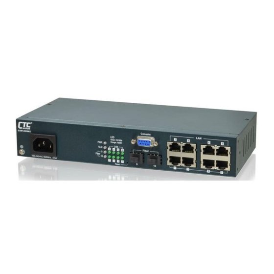
Chapter 2. Panels & LED Indicators This section describes the front panel of GSW-3208M2. The front panel of GSW-3208M2 provides LAN ports, SFP cages, reset push-button, console port and power port (AC or DC). LED indicators are also located on the front panel to provide real-time indications of link status. -
Page 11: Lan Connections
2.1.4 Reset Push-Button There is a recessed push-button switch used to reset GSW-3208M2 or to return it to factory defaults. Pressing the reset momentarily once will "warm boot" the switch. Pressing and holding the pushbutton switch for more than 3 seconds and then releasing will set the running configuration to the original factory default settings, including the original factory default IP address followed by a "warm boot". -
Page 12: Earth Grounding
Chapter 2 Panels & LED Indicators 2.1.6 Earth Grounding An earth ground hole (next to AC or DC power supply) is provided on the left side of the front panel with an earth ground sign next to it. Grounding the device can help to release leakage of electricity to the earth safely so as to reduce injuries from electromagnetic interference (EMI). -
Page 13: Chapter 3. Introduction To Cli
Simple Network Management Protocol (SNMP). The operator will use SNMP management software to manage and monitor the GSW-3208M2 switches on a network. This requires some configuration of the device to allow SNMP management. In addition, the network management platform will need to import and compile the proprietary MIB (management information base) file so that the management software knows "how"... -
Page 14: Cli Commands
Chapter 3 Introduction to CLI Username: admin Password: Login in progress... Welcome to CCLI (v1.2). Type 'help' or '?' to get help. > 3.4 CLI Commands 3.4.1 CLI Online Help While using the CLI, online help is always available by using 'help' command or typing '?' (question mark). Commands can be recalled by using the 'up/down arrow keys'. -
Page 15: Tcp/Ip Configuration Via Cli
Note: The <dns_source> parameter points to the static DNS server for the network. 3.4.2.4 Display TCP/IP Settings syntax: IP Configuration >ip configuration IP Configuration: ================= DHCP Client : Disabled DHCP Option 60 : GSW-3208M2 IP Address : 192.168.0.1 IP Mask : 255.255.255.0 IP Router : 0.0.0.0 DNS Server : 0.0.0.0... -
Page 16: Factory Default
Chapter 3 Introduction to CLI 3.4.3 Factory Default Syntax: System Restore Default <keep_ip> >system restore default > Note: To restore factory default but keep TCP/IP settings, use: "system restore default keep_ip" 3.4.4 Reboot Device Syntax: System Reboot >system reboot > 3.4.5 Admin Password Syntax: Security Switch Users Add <username>... -
Page 17: Chapter 4. Web Configuration & Operation
Web Configuration & Operation Chapter 4. Web Configuration & Operation 4.1 Home Page Using your favorite web browser, enter the IP address of the GSW-3208M2 in the browser's location bar. The factory default address is 192.168.0.1. 4.1.1 Login A standard login prompt will appear depending on the type of browser used. The example below is with Firefox browser. -
Page 18: Refresh
Chapter 4 Web Configuration & Operation 4.1.3 Refresh To update the screen, click the "Refresh" button. For automatic updating of the screen, the "Auto-refresh" tick box may be ticked. The screen will be auto refreshed every 3 seconds. Unless connected directly on a local LAN, we recommend not using the auto-refresh function as it does generate a bit of traffic. -
Page 19: System Configuration
Chapter 4 Web Configuration & Operation 4.2.1 System Configuration The configuration information entered here will be reported in the standard SNMP MIB2 for 'sysContact' (OID 1.3.6.1.2.1.1.4), 'sysName' (OID 1.3.6.1.2.1.1.5) and 'sysLocation' (OID 1.3.6.1.2.1.1.6). Remember to click the 'Save' button after entering the configuration information. 4.2.2 System Information The system information screen will display the configuration information, the hardware MAC address and version, the system time, the system "uptime"... -
Page 20: System Ipv6
Chapter 4 Web Configuration & Operation DHCP Option 60: Configure the DHCP option 60 vendor class ID. The allowed string length is 0 to 60, and the allowed content is the ASCII characters from 0x20 to 0x7E. IP Address: The IPv4 address of the interface is entered in dotted decimal notation. If DHCP is enabled, DHCP fails and the configured IP address is zero, DHCP will retry. -
Page 21: System Auto Provision Configuration
Chapter 4 Web Configuration & Operation 4.2.5 System Auto Provision Configuration Configure auto provision on this page. Auto Provision Mode: Indicates the auto provision operation mode. Possible modes are: Enabled: Enable auto provision mode operation. When auto provision mode operation is enabled, the device can download software and configuration automatically. -
Page 22: System Time
Chapter 4 Web Configuration & Operation 4.2.7 System Time Setup the device time. The setting example above is for Eastern Standard Time in the United States. Daylight savings time starts on the second Sunday in March at 2:00AM. Daylight savings ends on the first Sunday in November at 2:00AM. The daylight savings time offset is 60 minutes (1 hour). -
Page 23: System Log Configuration
Chapter 4 Web Configuration & Operation 4.2.8 System Log Configuration Configure System Log on this page. Server Mode: This sets the server mode operation. When the mode of operation is enabled, the syslog message will send out to syslog server (at the server address). The syslog protocol is based on UDP communication and received on UDP port 514. -
Page 24: System Detailed Log
Chapter 4 Web Configuration & Operation 4.2.10 System Detailed Log Displays individual log records. View each log, by ID number. 4.2.11 Alarm When the selected port or ports are link down, the ALM LED will light in "Orange". If you want to turn off this function, uncheck all ports. -
Page 25: Power Reduction (Green Ethernet)
Chapter 4 Web Configuration & Operation 4.3 Power Reduction (Green Ethernet) The configuration under the "Power Reduction" menu includes two power saving techniques. 4.3.1 Green Ethernet LED Configure the LED light intensity to reduce power consumption. The LED light intensity may be adjusted in a percentage of intensity during programmable time periods. In the above setting example, the LED intensity has been adjusted to 50% during daylight hours and reduced to only 10% intensity during night hours. -
Page 26: Thermal Protection
Chapter 4 Web Configuration & Operation Port: The port number. “All” rules apply to all ports. Enabled: Select the checkbox to enable EEE function on a port. By default, all ports (except Fiber port) are enabled with EEE function. EEE Urgent Queues: It is possible to minimize the latency for specific frames, by mapping the frames to a specific queue (done with QOS), and then mark the queue as an urgent queue. -
Page 27: Status
Chapter 4 Web Configuration & Operation Temperature settings for priority groups: Specify the temperature at which the ports with the corresponding priority will ° ° be turned off. Temperatures between 0 C and 255 C are supported. Port priorities: The priority the port belongs to. There are 4 priority levels supported. 4.4.2 Status Local Port: The port number. - Page 28 Chapter 4 Web Configuration & Operation Link: The current link state for each port is displayed graphically. Green indicates the link is up and red indicates that it is down. Current Speed: This column provides the current link speed (Auto nego, 10, 100, 1G) and duplex (fdx=Full Duplex, hdx=Half Duplex) of each port.
-
Page 29: Ports Auto Laser Shutdown
Chapter 4 Web Configuration & Operation 4.5.2 Ports Auto Laser Shutdown This page allows the user to inspect and configure the current setting for transceiver module Tx power. (ALS) Mode: Enable or disable the laser power of transceiver module shutdown automatically. Laser ON Period: The period is Tx laser power turn ON. -
Page 30: Ports Traffic Overview
Chapter 4 Web Configuration & Operation Vendor PN: The part number provided by SFP vendor. Vendor SN: The serial number provided by SFP vendor. Fiber Type: The type of fiber channel transmission media (multi-mode or single mode). Tx Power: The TX output power in dBm. Rx Power: The RX received optical power in dBm. -
Page 31: Ports Qos Statistics
Chapter 4 Web Configuration & Operation 4.5.6 Ports QoS Statistics This page provides statistics for the different queues for all switch ports. Port: The logical port for the settings contained in the same row. Qn: There are 8 QoS queues per port. Q0 is the lowest priority queue. Rx/Tx: The number of received and transmitted packets per queue. -
Page 32: Ports Detailed Statistics
Chapter 4 Web Configuration & Operation Conflict: Displays Conflict status of QCL entries. As H/W resources are shared by multiple applications, it may happen that resources are required to add a QCE may not be available. In that case it shows conflict status as 'Yes', otherwise it is always 'No'. -
Page 33: Security
Chapter 4 Web Configuration & Operation Rx CRC/Alignment: The number of frames received with CRC or alignment errors. Rx Undersize: The number of short frames received with valid CRC. Rx Oversize: The number of long frames received with valid CRC. Rx Fragments: The number of short frames received with invalid CRC. -
Page 34: Privilege Levels
Chapter 4 Web Configuration & Operation Add User User Name: Enter the new user name. Password: Enter the password for this user account. Password (again): Retype the password for this user account. Privilege Level: Select the appropriate privilege level for this user account. The allowed range is 1 to 15. If the privilege level value is 15, it can access all groups, i.e. -
Page 35: Auth Method
Chapter 4 Web Configuration & Operation Group Name: This name identifies the privilege group. In most cases, a privilege level group consists of a single module (e.g. LACP, RSTP or QoS), but a few of them contains more than one. The following description defines these privilege level groups in details: System: Contact, Name, Location, Timezone, Daylight Saving Time, Log. -
Page 36: Ssh
Chapter 4 Web Configuration & Operation Note: Methods that involve remote servers will time out if the remote servers are offline. In this case the next method is tried. Each method is tried from left to right and continues until a method either approves or rejects a user. If a remote server is used for primary authentication it is recommended to configure secondary authentication as 'local'. -
Page 37: Access Management
Chapter 4 Web Configuration & Operation Automatic Redirect: Indicates the HTTPS redirect mode operation. It applies only if HTTPS mode "Enabled" is selected. Automatically redirects HTTP of web browser to an HTTPS connection when both HTTPS mode and Automatic Redirect are enabled. -
Page 38: Access Management Statistics
Chapter 4 Web Configuration & Operation TELNET/SSH: Indicates that the matched host can access the switch from TELNET/SSH interface. Click the “Add New Entry” button to add a new entry. Click the “Delete” button to remove a newly-inserted entry or select the checkbox to remove a saved entry during the next save. -
Page 39: Snmp
Chapter 4 Web Configuration & Operation 4.6.1.7 SNMP 4.6.1.7.1 System Configuration Configure SNMP on this page. SNMP System Configuration Mode: Indicates the SNMP mode operation. Possible modes are: Enabled: Enable SNMP mode operation. Disabled: Disable SNMP mode operation. Version: Indicates the SNMP supported version. Possible versions are: SNMP v1: Set SNMP supported version 1. - Page 40 Chapter 4 Web Configuration & Operation SNMP Trap Configuration Configure SNMP trap on this page. Trap Mode: Indicates the SNMP trap mode operation. Possible modes are: Enabled: Enable SNMP trap mode operation. Disabled: Disable SNMP trap mode operation. Trap Version: Indicates the SNMP trap supported version. Possible versions are: SNMP v1: Set SNMP trap supported version 1.
-
Page 41: Snmpv3 Community Configuration
Chapter 4 Web Configuration & Operation Disabled: Disable dying gasp trap mode operation. Trap Inform Mode: Indicates the SNMP trap inform mode operation. Possible modes are: Enabled: Enable SNMP trap inform mode operation. Disabled: Disable SNMP trap inform mode operation. Trap Inform Timeout (seconds): Indicates the SNMP trap inform timeout. - Page 42 Chapter 4 Web Configuration & Operation simple agent, usmUserEngineID is always that agent's own snmpEngineID value. The value can also take the value of the snmpEngineID of a remote SNMP engine with which this user can communicate. In other words, if user engine ID equal system engine ID then it is local user;...
-
Page 43: Snmpv3 Group Configuration
Chapter 4 Web Configuration & Operation 4.6.1.7.4 SNMPv3 Group Configuration Configure SNMPv3 group table on this page. The entry index keys are Security Model and Security Name. Security Model: Indicates the security model that this entry should belong to. Possible security models are: v1: Reserved for SNMPv1. -
Page 44: Snmpv3 Access Configuration
Chapter 4 Web Configuration & Operation Click the “Add New Entry” button to add a new entry. Click the “Delete” button to remove a newly-inserted entry or select the checkbox to remove a saved entry during the next save. Click the “Save” button to save settings or changes. Click the “Reset”... -
Page 45: Rmon
Chapter 4 Web Configuration & Operation 4.6.1.8 RMON 4.6.1.8.1 RMON Statistics Configuration Remote monitoring is a standard specification that enables various network monitors to exchange network monitoring data. RMON provides the user with more freedom in selecting networking monitoring probes that meet their particular networking needs. -
Page 46: Rmon Alarm Configuration
Chapter 4 Web Configuration & Operation 4.6.1.8.3 RMON Alarm Configuration RMON Alarm configuration defines specific criteria that will generate response events. It can be set to test data over any specified time interval and can monitor absolute or changing values. Alarms can also be set to respond to rising or falling thresholds. -
Page 47: Rmon Event Configuration
Chapter 4 Web Configuration & Operation 4.6.1.8.4 RMON Event Configuration RMON Event Configuration page is used to set an action taken when an alarm is triggered. ID: Specifies an ID index. The range is 1~65535. Desc: Enters a descriptive comment for this entry. Type: Select an event type that will take when an alarm is triggered. -
Page 48: Rmon History Overview
Chapter 4 Web Configuration & Operation Broadcast: The total number of good packets received that were directed to the broadcast address. Multicast: The total number of good packets received that were directed to a multicast address. CRC Errors: The total number of packets received that had a length (excluding framing bits, but including FCS octets) of between 64 and 1518 octets. -
Page 49: Rmon Alarm Overview
Chapter 4 Web Configuration & Operation in hundredths of a percent. 4.6.1.8.7 RMON Alarm Overview ID: Display an alarm control index. Interval: Interval in seconds for sampling and comparing the rising and falling threshold. Variable: MIB object that is used to be sampled. Sample Type: The method of sampling the selected variable and calculating the value to be compared against the thresholds. -
Page 50: Network
Chapter 4 Web Configuration & Operation 4.6.2 Network 4.6.2.1 Port Security Port Security Limit Control can restrict the number of users that can access the switch based on users’ MAC address and VLAN ID on a per port basis. Once the number of users that wants to access the switch exceeds the specified number, a selected action will be taken immediately. - Page 51 Chapter 4 Web Configuration & Operation Port Configuration Port: Display the port number. “Port *” rules apply to all ports. Mode: Enable or disable port security limit control on a per port basis. To make limit control function work, port security limit control needs to be enabled globally and on a port.
-
Page 52: Switch Status
Chapter 4 Web Configuration & Operation 4.6.2.1.2 Switch Status User Module Legend User Module Name: The full name of a module that may request Port Security services. Abbr: This column is the abbreviation for the user module used in the “Users” column in the “Port Status”. Port Status Port: Port number. -
Page 53: Port Status
Chapter 4 Web Configuration & Operation 4.6.2.1.3 Port Status This page shows MAC addresses learned on a particular port. MAC Address: When “Port Security Limit Control” is enabled globally and on a port, MAC addresses learned on a port shows in here. VLAN ID: Display VLAN ID that is seen on this port. -
Page 54: Configuration
Chapter 4 Web Configuration & Operation 4.6.2.2.1 Configuration System Configuration Mode: Enable 802.1X and MAC-based authentication globally on the switch. If globally disabled, all ports are allowed to forward frames. Reauthentication Enabled: Select the checkbox to set clients to be re-authenticated after an interval set in "Reauthentication Period"... - Page 55 Chapter 4 Web Configuration & Operation the Guest VLAN is disabled on all ports. Guest VLAN ID: This VLAN ID is functional only when Guest VLAN is enabled. This is the value that a port’s Port VLAN ID is set to if a port is moved into the Guest VLAN. The range is 1~4095. Max.
-
Page 56: Switch Status
Chapter 4 Web Configuration & Operation Globally Disabled: 802.1X and MAC-based authentication are globally disabled. Link Down: 802.1X and MAC-based authentication are enabled but there is no link on a port. Authorized: The port is forced in authorized mode and the supplicant is successfully authorized. Unauthorized: The port is forced in unauthorized mode and the supplicant is not successfully authorized by the RADIUS server. -
Page 57: Port Statistics
Chapter 4 Web Configuration & Operation 4.6.2.2.3 Port Statistics Port State Admin State: Display the port’s current administrative state. Port Status: Display the port state. Port Counters Total: The number of valid EAPOL frames of any type that have been received & transmitted by the switch. Response ID: The number of valid EAPOL Response Identity frames that have been received &... -
Page 58: Acl
Chapter 4 Web Configuration & Operation 4.6.2.3 ACL ACL is a sequential list established to allow or deny users to access information or perform tasks on the network. In this switch, users can establish rules applied to port numbers to permit or deny actions or restrict rate limit. 4.6.2.3.1 Ports Port: The port number. -
Page 59: Rate Limiters
Chapter 4 Web Configuration & Operation 4.6.2.3.2 Rate Limiters Rate Limiter ID: Display every rate limiter ID. Rate: Specify the threshold above which packets are dropped. The allowed values are 0~3276700 pps or 1, 100, 200, 300…1000000 kbps. Unit: Select the unit of measure used in rate. 4.6.2.3.3 Access Control List Click on the to insert a new ACE entry. - Page 60 Chapter 4 Web Configuration & Operation ACE Configuration Ingress Port: Select the ingress port of the access control entry. Select “All” to apply an ACL rule to all ports or select a particular port. Policy Filter: Select the policy filter type. “Any” means no policy filter is assigned to this rule (or don’t care). Select “Specific”...
- Page 61 Chapter 4 Web Configuration & Operation MAC Parameter SMAC Filter: The type of source MAC address. Select “Any” to allow all types of source MAC addresses or select “Specific” to define a source MAC address. (This field is for ARP and Ethernet frame type only.) DMAC Filter: The type of destination MAC address.
- Page 62 Chapter 4 Web Configuration & Operation ARP Sender SMAC Match: Select “0” to indicate that the SHA (Sender Hardware Address) field in the ARP/RARP frame is not equal to source MAC address. Select “1” to indicate that SHA field in the ARP/RARP frame is equal to source MAC address.
-
Page 63: Acl Status
Chapter 4 Web Configuration & Operation 4.6.2.3.4 ACL Status This page shows the ACL status by different ACL users. Each row describes the ACE that is defined. It is a conflict if a specific ACE is not applied to the hardware due to hardware limitations. The maximum number of ACEs is 256 on each switch. -
Page 64: Dhcp
Chapter 4 Web Configuration & Operation Counter: The counter indicates the number of times the ACE was hit by a frame. Conflict: Indicate the hardware status of the specific ACE. The specific ACE is not applied to the hardware due to hardware limitations. -
Page 65: Dhcp Snooping Statistics
Chapter 4 Web Configuration & Operation Relay Server: Enter DHCP server IP address that is used by the switch’s DHCP relay agent. Relay Information Mode: Enable or disable DHCP Relay option 82 function. Please note that “Relay Mode” must be enabled before this function is able to take effect. -
Page 66: Dhcp Relay Statistics
Chapter 4 Web Configuration & Operation 4.6.2.4.4 DHCP Relay Statistics DHCP Relay Statistics Transmit to Server: The number of packets that are relayed from client to server. Transmit Error: The number of packets that resulted in errors while being sent to clients. Receive from Client: The number of packets received from server. -
Page 67: Ip Source Guard
Chapter 4 Web Configuration & Operation 4.6.2.5 IP Source Guard 4.6.2.5.1 Configuration IP Source Guard Configuration Mode: Enable or disable IP source guard globally. Translate dynamic to static: Click this button to translate dynamic entries to static ones. Port Mode Configuration Port: The port number. -
Page 68: Dynamic Table
Chapter 4 Web Configuration & Operation Click the “Delete” button to remove a newly-inserted entry or select the checkbox to remove a saved entry during the next save. Click the “Save” button to save settings or changes. Click the “Reset” button to restore changed settings to the default settings. 4.6.2.5.3 Dynamic Table The Dynamic IP Source Guard table shows entries sorted by port, VLAN ID, IP address and MAC address. -
Page 69: Static Table
Chapter 4 Web Configuration & Operation 4.6.2.6.2 Static Table Port: Select a port to which a static entry is bound. VLAN ID: Specify a configured VLAN ID. MAC Address: Specify an allowed source MAC address in ARP request packets. IP Address: Specify an allowed source IP address in ARP request packets. Click the “Add New Entry”... -
Page 70: Aaa
Chapter 4 Web Configuration & Operation 4.6.2.7 AAA 4.6.2.7.1 Configuration Common Server Configuration Timeout: The time the switch waits for a reply from an authentication server before it retransmits the request. Deadtime: Deadtime is the period during which the switch will not send new requests to a server that has failed to respond to a previous request. -
Page 71: Radius Overview
Chapter 4 Web Configuration & Operation Hostname: The hostname or IP address for the TACACS+ authentication server. Port: The UDP port to be used on the TACACS+ server for authentication. Key: Specify the secret key up to 63 characters. This is shared between the TACACS+ sever and the switch 4.6.2.7.2 RADIUS Overview RADIUS Authentication/Accounting Server Status Overview IP Address: The configured IP address and UPD port number. -
Page 72: Radius Details
Chapter 4 Web Configuration & Operation 4.6.2.7.3 RADIUS Details RADIUS Authentication Statistics for Server Access Accepts: The number of RADIUS Access-Accept packets (valid or invalid) received from the server. Access Rejects: The number of RADIUS Access-Reject packets (valid or invalid) received from the server. Access Challenges: The number of RADIUS Access-Challenge packets (valid or invalid) received from the server. - Page 73 Chapter 4 Web Configuration & Operation Disabled: The selected server is disabled. Not Ready: The server is enabled, but IP communication is not yet up and running. Ready: The server is enabled, IP communication is up and running, and the RADIUS module is ready to accept access attempts.
-
Page 74: Aggregation
Chapter 4 Web Configuration & Operation Round-Trip Time: The time interval (measured in milliseconds) between the most recent Response and the Request that matched it from the RADIUS accounting server. The granularity of this measurement is 100 ms. A value of 0 ms indicates that there hasn't been round-trip communication with the server yet. -
Page 75: Lacp
Chapter 4 Web Configuration & Operation 4.7.2 LACP The Switch supports dynamic Link Aggregation Control Protocol (LACP) which is specified in IEEE 802.3ad. Static trunks have to be manually configured at both ends of the link. In other words, LACP configured ports can automatically negotiate a trunked link with LACP configured ports on another devices. -
Page 76: System Status
Chapter 4 Web Configuration & Operation 4.7.2.2 System Status Aggr ID: Display the aggregation ID associated with the Link Aggregation Group (LAG). Partner System ID: LAG’s partner system ID (MAC address). Partner Key: The partner key assigned to this LAG. Partner Prio: The priority value of the partner. -
Page 77: Port Statistics
Chapter 4 Web Configuration & Operation 4.7.2.4 Port Statistics Port: The port number. LACP Received: The number of LACP packets received on a port. LACP Transmitted: The number of LACP packets transmitted by a port Discarded: The number of unknown and illegal packets that have been discarded on a port. 4.8 Loop Protection Loops sometimes occur in a network due to improper connecting, hardware problem or faulty protocol settings. -
Page 78: Status
Chapter 4 Web Configuration & Operation General Settings Enable Loop Protection: Enable or disable loop protection function. Transmission Time: The interval between each loop protection PDU sent on each port. Valid values are 1 to 10 seconds. Shutdown Time: The period for which a port will be kept disabled. Valid values are 0 to 604800 seconds. 0 means that a port is kept disabled until next device restart. -
Page 79: Spanning Tree
Chapter 4 Web Configuration & Operation 4.9 Spanning Tree For some networking services, always-on connections are required to ensure that end users’ online related activities are not interrupted due to unexpected disconnections. In these circumstances, multiple active paths between network nodes are established to prevent disconnections from happening. - Page 80 Chapter 4 Web Configuration & Operation multiple bridges and interfaces then you need to adjust the priorities to achieve optimized performance. For MSTP operation, this is the priority of the CIST. Otherwise, this is the priority of the STP/RSTP bridge. Forward Delay: Fort STP bridges, the Forward Delay is the time spent in each Listening and Learning state before the Forwarding state is entered.
-
Page 81: Msti Mapping
Chapter 4 Web Configuration & Operation 4.9.2 MSTI Mapping Configuration Identification Configuration Name: The name for this MSTI. By default, the switch’s MAC address is used. The maximum length is 32 characters. In order to share spanning trees for MSTI, bridges must have the same configuration name and revision value. Configuration Revision: The revision number for this MSTI. -
Page 82: Cist Ports
Chapter 4 Web Configuration & Operation MSTI: Display MSTI instance number. “MSTI All” priority rule applies to all ports. Priority: Select an appropriate priority for each MSTI instance. Bridge priority is used in selecting the root device, root port, and designated port. The device with the highest priority becomes the root device. However, if all devices have the same priority, the device with the lowest MAC address will then become the root device. -
Page 83: Msti Ports
Chapter 4 Web Configuration & Operation Forced True: It is a point-to-point connection. Forced False: It is a shared medium connection. 4.9.5 MSTI Ports Port: The port number. Path Cost: Path cost is used to determine the best path between devices. If “Auto” mode is selected, the system automatically detects the speed and duplex mode to decide the path cost. - Page 84 Chapter 4 Web Configuration & Operation Topology Flag: The current state of the Topology Change Notification flag for this bridge instance. Topology Change Last: The time since this spanning tree was last configured. STP Detailed Bridge Status Click the MSTI instance to view STP detailed bridge status. Bridge Instance: The bridge instance.
-
Page 85: Port Status
Chapter 4 Web Configuration & Operation Blocking: Ports only receive BPDU messages but do not forward them. Learning: Port has transmitted configuration messages for an interval set by the Forward Delay parameter without receiving contradictory information. Port address table is cleared, and the port begins learning addresses Forwarding: Ports forward packets and continue to learn addresses. -
Page 86: Mvr
Chapter 4 Web Configuration & Operation Transmitted & Received MSTP/RSTP/STP: The number of MSTP/RSTP/STP configuration BPDU messages transmitted and received on a port. Transmitted & Received TCN: The number of TCN messages transmitted and received on a port. Discarded Unknown/Illegal: The number of unknown and illegal packets discarded on a port. 4.10 MVR Multicast VLAN Registration protocol (MVR) allows a media server to transmit multicast stream in a single multicast VLAN when clients receiving multicast VLAN stream can reside in different VLANs. - Page 87 Chapter 4 Web Configuration & Operation Mode: Two MVR operation modes are provided. Dynamic: MVR allows dynamic MVR membership reports on source ports. (This is the default mode.) Compatible: MVR membership reports are forbidden on source ports. Tagging: Specify whether IGMP/MLD control frames will be sent tagged with MVR VID or untagged. Priority: Specify the priority for transmitting IGMP/MLD control frames.
-
Page 88: Statistics
Chapter 4 Web Configuration & Operation VLAN Name: Display the selected entry’s multicast VLAN Name. This field is not editable. Start Address: Enter the starting IPv4 or IPv6 multicast streaming address that will be used as a streaming channel. End Address: Enter the ending IPv4 or IPv6 multicast streaming address that will be used as a streaming channel. Channel Name: Enter a descriptive name for this multicast VLAN. -
Page 89: Mvr Sfm Information
Chapter 4 Web Configuration & Operation Groups: Group ID Port Members: Ports that belong to this group. 4.10.4 MVR SFM Information VLAN ID: VLAN ID of the group. Group: The group address. Port: Switch port number. Mode: Indicate the filtering mode maintained per (VLAN ID, port number, Group Address) basis. It can be either Include or Exclude. -
Page 90: Basic Configuration
Chapter 4 Web Configuration & Operation 4.11.1.1 Basic Configuration IGMP Snooping Configuration: Global Configuration Snooping Enabled: Select the checkbox to globally enable IGMP Snooping feature. When enabled, this device will monitor network traffic and determine which hosts will receive multicast traffic. The switch can passively monitor or snoop on IGMP Query and Report packets transferred between IP multicast routers and IP multicast service subscribers to identify the multicast group members. -
Page 91: Vlan Configuration
Chapter 4 Web Configuration & Operation 4.11.1.2 VLAN Configuration This page is used to configure IGMP Snooping for an interface. VLAN ID: Specify VLAN ID for IGMP snooping. Snooping Enabled: Select the checkbox to enable snooping feature on an interface basis. When enabled, the switch will monitor network traffic on the specified interface to determine which hosts want to receive multicast services. -
Page 92: Port Group Filtering
Chapter 4 Web Configuration & Operation 4.11.1.3 Port Group Filtering The Port Filtering Configuration page is to filter specific multicast traffic on a per port basis. Before you select a filtering profile for filtering purposes, you must set up profiles in IPMC Profile page. Port: The port number. -
Page 93: Groups Information
Chapter 4 Web Configuration & Operation V2 Reports Received: The number of Received V2 Reports. V2 Leaves Received: The number of Received V2 Leaves. Router Port Port: The port number. Status: Indicate whether a specific port is a router port or not. 4.11.1.5 Groups Information VLAN ID: Display the VLAN ID of the group. -
Page 94: Mld Snooping
Chapter 4 Web Configuration & Operation 4.11.2 MLD Snooping Multicast Listener Discovery (MLD) snooping, similar to IGMP snooping for IPv4, operates on IPv6 for multicast traffic. In other words, MLD snooping configures ports to limit or control IPv6 multicast traffic so that multicast traffic is forwarded to ports (or users) who want to receive it. -
Page 95: Vlan Configuration
Chapter 4 Web Configuration & Operation Router Port: Select the checkbox on a given port to assign it as a router port. If MLD snooping cannot locate the MLD querier, you can manually designate a port which is connected to a known MLD querier (i.e., a multicast router/switch). This interface will then join all the current multicast groups supported by the attached router/switch to ensure that multicast traffic is passed to all appropriate interfaces within the switch. -
Page 96: Port Group Filtering
Chapter 4 Web Configuration & Operation Click the “Delete” button to remove a newly-inserted entry or select the checkbox to remove a saved entry during the next save. Click the “Save” button to save settings or changes. Click the “Reset” button to restore changed settings to the default settings. 4.11.2.3 Port Group Filtering Port: Select a port number to be used for this rule. -
Page 97: Groups Information
Chapter 4 Web Configuration & Operation V1 Leaves Received: The number of Received V1 Leaves. Router Port Port: The port number. Status: Indicate whether a specific port is a router port or not. 4.11.2.5 Groups Information VLAN ID: Display the VLAN ID of the group. Groups: Display the group address. -
Page 98: Configuration
Chapter 4 Web Configuration & Operation neighbour devices. Details such as port description, system name, system description, system capabilities, management address can be sent and received on this device. The “LLDP” menu contains the following sub menus. Select the appropriate menu to set up detailed configurations. 4.12.1 Configuration LLDP Parameters Tx Interval: Specify the interval between LLDP frames are sent to its neighbours for updated discovery information. -
Page 99: Lldp-Med
Chapter 4 Web Configuration & Operation CDP Aware: CDP aware operation is used to decode incoming CDP (Cisco Discovery Protocol) frames. If enabled, CDP TLVs that can be mapped into a corresponding field in the LLDP neighbors table are decoded, all others are discarded. CDP TLVs are mapped into LLDP neighbors table as shown below: Optional TLVs: LLDP uses several attributes to discover neighbour devices. - Page 100 Chapter 4 Web Configuration & Operation Floors: Representing altitude in a form more relevant in buildings which have different floor-to-floor dimensions. An altitude = 0.0 is meaningful even outside a building, and represents ground level at the given latitude and longitude. Inside a building, 0.0 represents the floor level associated with ground level at the main entrance.
-
Page 101: Neighbours
Chapter 4 Web Configuration & Operation Postal community name: Example: Leonia. P.O. Box: Example: 12345. Additional code: Example: 1320300003. Emergency Call Service Emergency Call Service: Emergency Call Service (e.g. E911 and others), such as defined by TIA or NENA. Policies Policy ID: Specify the ID for this policy. -
Page 102: Lldp-Med Neighbours
Chapter 4 Web Configuration & Operation 4.12.4 LLDP-MED Neighbours This page displays information about LLDP-MED neighbours detected on the network. 4.12.5 Neighbours EEE Information Local Port: The port for this switch on which the LLDP frame was received. Tx Tw: The link partner's maximum time that transmit path can hold-off sending data after deassertion of LPI. Rx Tw: The link partner's time that receiver would like the transmitter to hold-off to allow time for the receiver to wake from sleep. -
Page 103: Port Statistics
Chapter 4 Web Configuration & Operation 4.12.6 Port Statistics Global Counters Total Neighbours Entries Added: Shows the number of new entries added since the switch was rebooted, and for which the remote TTL has not yet expired. Total Neighbors Entries Deleted: The number of LLDP neighbors which have been removed from the LLDP remote systems MIB for any reason. -
Page 104: Mac Table
Chapter 4 Web Configuration & Operation 4.13 MAC Table The “MAC Table” menu contains configuration and status sub menu. Select the configuration page to set up detailed configuration 4.13.1 Configuration Disable Automatic Aging: Learned MAC addresses will appear in the table permanently. Aging Time: Set up the aging time for a learned MAC to be appeared in MAC learning table. -
Page 105: Mac Address Table
Chapter 4 Web Configuration & Operation Click the “Add New Static Entry” button to insert a new entry to the list. Click the “Delete” button to remove a newly-inserted entry or select the checkbox to remove a saved entry during the next save. -
Page 106: Vid Translation Mapping
Chapter 4 Web Configuration & Operation Group ID: The total VLAN Translation group can be used is 11 which is automatically created in Group Mapping Table when entering “Port to Group Mapping” page. A port can be mapped to any of the groups. Multiple ports can be mapped to a single group with the same Group ID. -
Page 107: Membership Configuration
Chapter 4 Web Configuration & Operation the entire network, VLANs can help group devices that communicate frequently with other in the same VLAN so as to divide the entire network into several broadcast domains. VLANs make changes of devices or relocation more easily: In traditional networks, when moving a device geographically to a new location (for example, move a device in floor 2 to floor 4), the network administrator may need to change the IP or even subnet of the network or require re-cabling. -
Page 108: Ports Configuration
Chapter 4 Web Configuration & Operation 4.15.2 Ports Configuration Ethertype for Custom S-ports: Specify ether type used for customer s-ports. VLAN Port Configuration Port: The port number. “All” settings apply to all ports. Port Type: There are four port types available. Each port type’s ingress and egress action is described in the following table. -
Page 109: Membership Status
Chapter 4 Web Configuration & Operation Ingress Filtering: If Ingress Filtering is enabled and the ingress port is not a member of a VLAN, the frame from the ingress port is discarded. By default, ingress filtering is disabled. Frame Type: Select the accepted frame types. Available options include All (accept all frames), Tagged (accept only tagged frames), Untagged (accept only untagged frames). -
Page 110: Private Vlans
Chapter 4 Web Configuration & Operation Ethernet frames leaving a port match the UVID, these frames will be sent untagged. Conflicts: Display whether conflicts exist or not. When a software module requests to set VLAN membership or VLAN port configuration, the following conflicts can occur: *Functional conflicts between features. -
Page 111: Port Isolation
Chapter 4 Web Configuration & Operation 4.16.2 Port Isolation Private VLAN is used to group ports together so as to prevent communications within PVLAN. Port Isolation is used to prevent communications between customer ports in a same Private VLAN. The port that is isolated from others cannot forward any unicast, multicast or broadcast traffic to any other ports in the same PVLAN. -
Page 112: Membership Status
Chapter 4 Web Configuration & Operation Click the “Reset” button to restore changed settings to the default settings. 5.17.1.2 Membership Status This page shows the status of current VCL rules. MAC Address: Display the configured MAC addresses. VLAN ID: Display the VLAN ID of this membership entry. Port Members: Display ports that accept the configured MAC address. -
Page 113: Group To Vlan
Chapter 4 Web Configuration & Operation Ethernet: Ether Type (etype) value. By default, it is set to 0x0800. The range allowed is 0x0600 to 0xffff. SNAP: This includes OUI (Organizationally Unique Identifier) and PID (Protocol ID) values. OUI: A value in the format of xx-xx-xx where each pair (xx) in the string is a hexadecimal value in the ranges of 0x00-0xff. -
Page 114: Ip Subnet-Based Vlan
Chapter 4 Web Configuration & Operation 4.17.3 IP Subnet-based VLAN IP Subnet-based VLAN configuration is to map untagged ingress frames to a specific VLAN if the source address is found in the IP subnet-to-VLAN mapping table. When IP subnet-based VLAN classification is enabled, the source address of untagged ingress frame is checked against the IP subnet-to-VLAN mapping table. -
Page 115: Configuration
Chapter 4 Web Configuration & Operation 4.18.1 Configuration Voice VLAN Configuration Mode: Enable or disable Voice VLAN function on this switch. VLAN ID: Assign a VLAN ID to this Voice VLAN. Only one Voice VLAN is supported on the switch. By default, VLAN 1000 is set. -
Page 116: Oui
Chapter 4 Web Configuration & Operation Forced: Enable Voice VLAN feature on a particular port. Security: Enable or disable security filtering feature on a per port basis. When enabled, any non-VoIP packets received on a port with Voice VLAN ID will be discarded. VoIP traffic is identified by source MAC addresses configured in the telephony OUI list or through LLDP which is used to discover VoIP devices attached to the switch. -
Page 117: Qos
Chapter 4 Web Configuration & Operation 4.19 QoS Network traffic is always unpredictable and the only basic assurance that can be offered is the best effort traffic delivery. To overcome this challenge, Quality of Service (QoS) is applied throughout the network. This ensures that network traffic is prioritized according to specified criteria and receives preferential treatments. -
Page 118: Port Policing
Chapter 4 Web Configuration & Operation 4.19.2 Port Policing This page allows users to set each port’s allowed bandwidth. Port: The port number. “All” settings apply to all ports. Enabled: Select the checkbox to enable port policing function on a port. Rate: Indicate the rate for the policer. - Page 119 Chapter 4 Web Configuration & Operation This page allows you to set up the Schedulers and Shapers for a specific port. Scheduler Mode: The device offers two modes to handle queues. Strict mode: This gives egress queues with higher priority to be transmitted first before lower priority queues are serviced.
-
Page 120: Port Shaping
Chapter 4 Web Configuration & Operation Rate: Indicate the rate for Port Shaper. By default, 500kbps is used. Allowed range for kbps is 100 to 1000000. Allowed range for Mbps is 1 to 3300Mbps. Unit: Select the rate of measure 4.19.4 Port Shaping This displays each port’s queue shaper and port shaper’s rate. -
Page 121: Port Dscp
Chapter 4 Web Configuration & Operation QoS class/DP level: Show the mapping options for QoS class values and DP levels (drop precedence). PCP: Remarks matching egress frames with the specified Priority Code Point (or User Priority) value. (Range: 0-7; Default: DEI: Remarks matching egress frames with the specified Drop Eligible Indicator. -
Page 122: Dscp-Based Qos
Chapter 4 Web Configuration & Operation Disable: Egress rewriting is disabled. Enable: Enable egress rewriting is enabled but with remapping. Remap DP aware: Frame with DSCP from analyzer is remapped and remarked with the remapped DSCP value. Depending on the frame’s DP level, the remapped DSCP value is either taken from the DSCP Translation table, Egress Remap DP0 or DP1 field. -
Page 123: Dscp Translation
Chapter 4 Web Configuration & Operation 4.19.8 DSCP Translation DSCP: DSCP value in ingress packet. DSCP range is from 0 to 63. Ingress Translate: Enable Ingress Translation of DSCP values based on the specified classification method. Ingress Classify: Enable classification at ingress side as defined in the QoS port DSCP Configuration Table. Egress Remap DP0: Remap DP0 value to the selected DSCP value. -
Page 124: Qos Control List
Chapter 4 Web Configuration & Operation QoS Class: List of actual QoS class values. DPL: List of actual DPL values DSCP: Select the DSCP value to map QoS class and DPL value. DSCP value selected for “*” will map to all QoS class and DPL value. - Page 125 Chapter 4 Web Configuration & Operation Once is clicked in display page, the following page will appear. QCE Configuration Port Members: Select ports that use this rule. Key Parameters Tag: Select VLAN tag type (Tag or Untag). By default, any type is used. VID: Select VID preference.
- Page 126 Chapter 4 Web Configuration & Operation Control: Control field may contain command, response, or sequence information depending on whether the LLC frame type is Unnumbered, Supervisory, or Information. By default, any is used. Select specific to indicate a value (0x00 to 0xFF). SNAP: SubNetwork Access Protocol can be distinguished by an OUI and a Protocol ID.
-
Page 127: Storm Control
Chapter 4 Web Configuration & Operation 4.19.11 Storm Control Storm Control is used to keep a network from downgraded performance or a complete halt by setting up a threshold for traffic like broadcast, unicast and multicast. When a device on the network is malfunctioning or application programs are not well designed or properly configured, storms may occur and will degrade network performance or even cause a complete halt. -
Page 128: Upnp
Chapter 4 Web Configuration & Operation 4.21 UPnP Mode: Enable or disable UPnP operation. TTL: TTL (Time to live) is used to configure how many steps an UPnP advertisement can travel before it disappears. Advertising Duration: This defines how often an UPnP advertisement is sent. The duration is carried in Simple Service Discover Protocol (SSDP) packets which informs a control point how often it should receive a SSDP advertisement message from the switch. -
Page 129: Ping6
Chapter 4 Web Configuration & Operation 4.22.2 Ping6 This Ping function is for ICMPv6 packets. IP Address: Enter the IP address that you wish to ping. Ping Length: The size or length of echo packets. Ping Count: The number of echo packets will be sent. Ping Interval: The time interval between each ping request. -
Page 130: Maintenance
Chapter 4 Web Configuration & Operation Cross A: Abnormal cross-pair coupling with pair A Cross B: Abnormal cross-pair coupling with pair B Cross C: Abnormal cross-pair coupling with pair C Cross D: Abnormal cross-pair coupling with pair D Length A/B/C/D: The length (in meters) of the cable pair. -
Page 131: Software
Chapter 4 Web Configuration & Operation 4.23.3 Software 4.23.3.1 Upload Update the latest Firmware file. Select a Firmware file from your local device and then click “Upload” to start updating. 4.23.3.2 Image Select Select the image file to be used in this device. 4.23.4 Configuration 4.23.4.1 Save Save the current running configurations in XML format in your local device. -
Page 132: Appendix A: Acronyms
Appendix A Acronyms Appendix A: Acronyms ACE is an acronym for Access Control Entry. It describes access permission associated with a particular ACE ID. There are three ACE frame types (Ethernet Type, ARP, and IPv4) and two ACE actions (permit and deny). The ACE also contains many detailed, different parameter options that are available for individual application. - Page 133 Appendix A Acronyms DHCP DHCP is an acronym for Dynamic Host Configuration Protocol. It is a protocol used for assigning dynamic IP addresses to devices on a network. DHCP Relay DHCP Relay is used to forward and to transfer DHCP messages between the clients and the server when they are not on the same subnet domain.
- Page 134 Appendix A Acronyms connection to a particular port on a remote host (port 80 by default). An HTTP server listening on that port waits for the client to send a request message. HTTPS HTTPS is an acronym for Hypertext Transfer Protocol over Secure Socket Layer. It is used to indicate a secure HTTP connection.
- Page 135 Appendix A Acronyms IPMC Profile IPMC Profile is an acronym for IP MultiCast Profile. IPMC Profile is used to deploy the access control on IP multicast streams. IP Source Guard IP Source Guard is a secure feature used to restrict IP traffic on DHCP snooping untrusted ports by filtering traffic based on the DHCP Snooping Table or manually configured IP Source Bindings.
- Page 136 Appendix A Acronyms Mirroring For debugging network problems or monitoring network traffic, the switch system can be configured to mirror frames from multiple ports to a mirror port. (In this context, mirroring a frame is the same as copying the frame.) Both incoming (source) and outgoing (destination) frames can be mirrored to the mirror port.
- Page 137 Appendix A Acronyms A LLDP frame contains multiple TLVs For some TLVs it is configurable if the switch shall include the TLV in the LLDP frame. These TLVs are known as optional TLVs. If an optional TLVs is disabled the corresponding information is not included in the LLDP frame.
- Page 138 Appendix A Acronyms PPPoE PPPoE is an acronym for Point-to-Point Protocol over Ethernet. It is a network protocol for encapsulating Point-to- Point Protocol (PPP) frames inside Ethernet frames. It is used mainly with ADSL services where individual users connect to the ADSL transceiver (modem) over Ethernet and in plain Metro Ethernet networks (Wikipedia). Private VLAN In a private VLAN, PVLANs provide layer 2 isolation between ports within the same broadcast domain.
- Page 139 Appendix A Acronyms RDI is an acronym for Remote Defect Indication. It is a OAM functionality that is used by a MEP to indicate defect detected to the remote peer MEP. Router Port A router port is a port on the Ethernet switch that leads switch towards the Layer 3 multicast device. RSTP In 1998, the IEEE with document 802.1w introduced an evolution of STP: the Rapid Spanning Tree Protocol, which provides for faster spanning tree convergence after a topology change.
- Page 140 Appendix A Acronyms SPROUT Stack Protocol using ROUting Technology. An advanced protocol for almost instantaneous discovery of topology changes within a stack as well as election of a master switch. SPROUT also calculates parameters for setting up each switch to perform shortest path forwarding within the stack. SSID Service Set Identifier is a name used to identify the particular 802.11 wireless LANs to which a user wants to attach.
- Page 141 Appendix A Acronyms TELNET TELNET is an acronym for TELetype NETwork. It is a terminal emulation protocol that uses the Transmission Control Protocol (TCP) and provides a virtual connection between TELNET server and TELNET client. TELNET enables the client to control the server and communicate with other servers on the network. To start a Telnet session, the client user must log in to a server by entering a valid username and password.
- Page 142 Appendix A Acronyms VLAN Virtual LAN. A method to restrict communication between switch ports. VLANs can be used for the following applications: VLAN unaware switching: This is the default configuration. All ports are VLAN unaware with Port VLAN ID 1 and members of VLAN 1.
- Page 143 Appendix A Acronyms WPS is an acronym for Wi-Fi Protected Setup. It is a standard for easy and secure establishment of a wireless home network. The goal of the WPS protocol is to simplify the process of connecting any home device to the wireless network (Wikipedia).
- Page 144 This page is intentionally left blank. Date Version Description 2015/8/26 Preliminary version...
Need help?
Do you have a question about the GSW-3208M2 and is the answer not in the manual?
Questions and answers