CTC Union GSW-1005MS User Manual
Managed gigabit ethernet cpe switch
Hide thumbs
Also See for GSW-1005MS:
- Quick installation manual (2 pages) ,
- Quick installation manual (2 pages)
Table of Contents
Advertisement
Advertisement
Table of Contents

Related Manuals for CTC Union GSW-1005MS


Summary of Contents for CTC Union GSW-1005MS
- Page 1 GSW-1005MS Managed Gigabit Ethernet CPE Switch...
- Page 3 CTC Union Technologies makes no warranty, representation, or guarantee regarding the suitability of its products for any particular purpose, nor does CTC Union assume any liability arising out of the application or use of any product and specifically disclaims any and all liability, including without limitation any consequential or incidental damages.
- Page 4 GSW-1005MS Managed Gigabit Ethernet 5TP+1FX CPE Switch This document is the current official release manual. Please check CTC Union's website for any updated manual or contact us by E-mail at sales@ctcu.com. Please address any comments for improving this manual or to point out omissions or errors to marketing@ctcu.com.
- Page 5 Table of Contents CHAPTER 1. INTRODUCTION ............................7 1.1 W ..................................7 ELCOME 1.2 P ..............................7 RODUCT ESCRIPTION 1.3 P ............................... 7 RODUCT EATURES 1.4 P ..............................8 RODUCT PECIFICATIONS CHAPTER 2. INSTALLATION............................9 2.1 I ................................9 NTRODUCTION 2.1.1 Mounting ................................
- Page 6 Table of Contents...
-
Page 7: Chapter 1 Introduction
LED display. When GSW-1005MS is deployed as a stand-alone solution, it incorporates an easy to use Web user interface for operation, administration and maintenance both local and remotely. All of the enabled Layer 2 features and functions of GSW-1005MS can be configured and monitored via web interface and SNMP management. -
Page 8: Product Specifications
Chapter 1 Introduction 1.4 Product Specifications Standards IEEE 802.3 10Base-T 10Mbit/s Ethernet IEEE 802.3u 100Base-TX, 100Base-FX, Fast Ethernet IEEE 802.3ab 1000Base-T Gbit/s Ethernet over twisted pair IEEE 802.3z 1000Base-X Gbit/s Ethernet over Fiber-Optic IEEE 802.1d STP (Spanning Tree Protocol) IEEE 802.1w RSTP (Rapid Spanning Tree Protocol ) IEEE 802.1s MSTP (Multiple Spanning Tree Protocol ) -
Page 9: Chapter 2 Installation
Chapter 2 Installation Chapter 2. Installation 2.1 Introduction GSW-1005MS is designed for placing on a desktop or optionally can be used with fiber cable tray. The units come without fiber tray from the factory. 2.1.1 Mounting The fiber tray installation will be written here. - Page 10 2.2.1 Power GSW-1005MS uses an external AC power adapter that supports wide voltage range input and is of a 'green' power efficiency design. Plug the power adapter's DC plug into the GSW-1005MS prior to plugging the adapter into the AC power source.
- Page 11 Chapter 2 Installation 2.2.5 LED Indicators Top of unit...
- Page 12 Chapter 2 Installation...
-
Page 13: Chapter 3 Configuration And Operation
The first method of configuration/management uses a Web Browser. This requires that networking be configured so that the device can be accessed via a LAN port. Accessing the GSW-1005MS from a network allows for both local and remote management. - Page 14 Chapter 3 Configuration and Operation 3.2.1 CLI Online Help While using the CLI, online help is always available by using 'help' command or typing '?' (question mark). Commands may be 'auto-completed' by pressing [TAB] and previous commands can be recalled by using the 'up/down arrow keys'.
-
Page 15: Factory Default
Chapter 3 Configuration and Operation 3.2.2.3 DNS Server syntax: IP DNS <dns_source> >ip dns 192.168.0.1 > note: The <dns_source> parameter points to the static DNS server for the network. 3.2.2.4 Display TCP/IP Settings syntax: IP Configuration >ip configuration IP Configuration: ================= DHCP Client : Disabled... - Page 16 Chapter 3 Configuration and Operation 3.3 Web Operation 3.3.1 Home Page Using your favorite web browser, enter the IP address of the GSW-1005MS in the browser's location bar. The factory default address is 192.168.0.1. 3.3.1.1 Login A standard login prompt will appear depending on the type of browser used. The example below is with Firefox browser.
- Page 17 3.3.1.4 Help System The GSW-1005MS has an online "help" system to aid the engineer when setting the parameters of the device. Each functional setting page is accompanied by a specific "help" for that functional page. The user can display this help "pop up"...
- Page 18 Chapter 3 Configuration and Operation 3.3.2.2 System Information The system information screen will display the configuration information, the hardware MAC address and version, the system time, the system "uptime" and the software version and build date. 3.3.2.3 System IP Setup the IP configuration, interface and routes DHCP Client: Enable the DHCP client by checking this box.
- Page 19 Chapter 3 Configuration and Operation 3.3.2.4 System IPv6 Configure the switch-managed IPv6 information on this page. The Configured column is used to view or change the IPv6 configuration. The Current column is used to show the active IPv6 configuration. Auto Configuration: Enable IPv6 auto-configuration by checking this box.
- Page 20 Chapter 3 Configuration and Operation 3.3.2.6 System NTP Configuration Configure NTP (Network Time Protocol) on this page. Mode: Indicates the NTP mode operation. Possible modes are: * Enabled: Enable NTP client mode operation. * Disabled: Disable NTP client mode operation. Server #: Provides the IPv4 or IPv6 address of a NTP server.
- Page 21 Chapter 3 Configuration and Operation Daylight Saving Time Configuration Daylight Saving Time: This is used to set the clock forward or backward according to the configurations set below for a defined Daylight Saving Time duration. Select 'Disable' to disable the Daylight Saving Time configuration. Select 'Recurring' and configure the Daylight Saving Time duration to repeat the configuration every year.
- Page 22 Chapter 3 Configuration and Operation 3.3.2.9 System Log Information Displays the collected log information. Level: Use this pull down to display all messages or messages of type info, warning or error. Clear Level: Use this pull down to clear selected message types from the log. Browsing buttons: Use these buttons to quickly go to the beginning or end of the log or to page through the log.
- Page 23 Chapter 3 Configuration and Operation 3.3.3 Power Reduction (Green Ethernet) The configuration under the "Power Reduction" menu includes two power saving techniques. 3.3.3.1 Green Ethernet LED Configure the LED light intensity to reduce power consumption. The LED light intensity may be adjusted in a percentage of intensity during programmable time periods. In the above setting example, the LED intensity has been adjusted to 50% during daylight hours and reduced to only 10% intensity during night hours.
- Page 24 Chapter 3 Configuration and Operation EEE Urgent Queues It is possible to minimize the latency for specific frames, by mapping the frames to a specific queue (done with QOS), and then mark the queue as an urgent queue. When an urgent queue gets data to be transmitted, the circuits will be powered up at once and the latency will be reduced to the wakeup time.
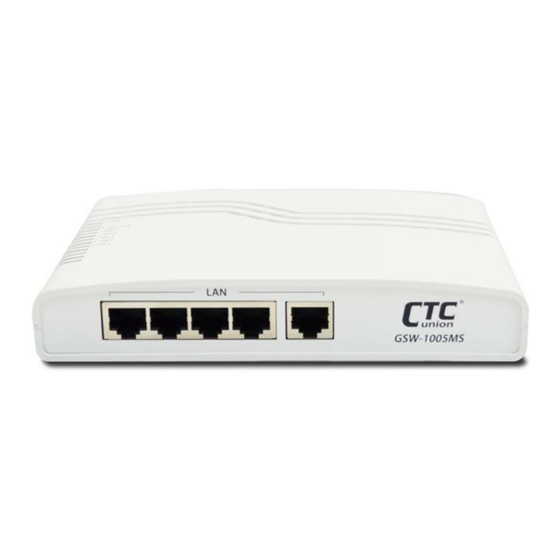
- Page 25 Port: GSW-1005MS are managed gigabit switches with 5 electrical LAN ports numbered 1~5 and 1 fiber optical port (for SFP module) numbered 6. Each logical port number is displayed in a row. The select all "*" port will apply actions on all ports.
- Page 26 Chapter 3 Configuration and Operation 3.3.5.2 Ports Auto Laser Shutdown This page allows the user to inspect and configure the current setting for transceiver module Tx power. ALS mode: Enable/Disable the laser power of transceiver module shutdown automatically. Laser ON Period: The period is Tx laser power turn ON.
- Page 27 Chapter 3 Configuration and Operation 3.3.5.5 Ports Traffic Overview Displays a comprehensive overview of traffic on all ports. The displayed counters are: Port * The logical port (1~6) for the data contained in the same row. Packets * The number of received and transmitted packets per port. Bytes * The number of received and transmitted bytes per port.
- Page 28 Chapter 3 Configuration and Operation 3.3.5.7 Ports QCL Status This page shows the QCL status by different QCL users. Each row describes the QCE that is defined. It is a conflict if a specific QCE is not applied to the hardware due to hardware limitations.
- Page 29 Chapter 3 Configuration and Operation 3.3.5.8 Ports Detailed Statistics This page provides detailed traffic statistics for a specific switch port. The displayed counters are the totals for receive and transmit, the size counters for receive and transmit, and the error counters for receive and transmit. Use the port select pull down to select which switch port details to display.
- Page 30 Chapter 3 Configuration and Operation Transmit Error Counters: Tx Drops The number of frames dropped due to output buffer congestion. Tx Late/Exc. Coll. The number of frames dropped due to excessive or late collisions. 3.3.6 Security Under the security heading are three major icons, switch, network and RADIUS. edit here 3.3.6.1 Users This page provides an overview of the current users.
- Page 31 Chapter 3 Configuration and Operation...
- Page 32 Chapter 3 Configuration and Operation Group Name: * This name identifies the privilege group. In most cases, a privilege level group consists of a single module (e.g. LACP, RSTP or QoS), but a few of them contains more than one. The following description defines these privilege level groups in details: * System: Contact, Name, Location, Timezone, Daylight Saving Time, Log.
- Page 33 Chapter 3 Configuration and Operation 3.3.5.4 SSH Configure SSH on this page. Mode: Indicates the SSH mode operation. Possible modes are: * Enabled: Enable SSH mode operation. (default) * Disabled: Disable SSH mode operation. note: SSH is preferred to Telnet, unless the management network is trusted. Telnet passes authentication credentials in plain text, making those credentials susceptible to packet capture and analysis.
- Page 34 Chapter 3 Configuration and Operation 3.3.5.7 Access Management Statistics This page provides statistics for access management. Interface: The interface type through which any remote host can access the switch. Received Packets: The number of received packets from the interface when access management mode is enabled. Allowed Packets: The number of allowed packets from the interface when access management mode is enabled.
- Page 35 Chapter 3 Configuration and Operation Trap Version: Indicates the SNMP trap supported version. Possible versions are: * SNMP v1: Set SNMP trap supported version 1. * SNMP v2c: Set SNMP trap supported version 2c. * SNMP v3: Set SNMP trap supported version 3. Trap Community: Indicates the community access string when sending SNMP trap packet.
- Page 36 Chapter 3 Configuration and Operation When the "specific" radio button is selected, a popup graphic with port check boxes allows selection specific ports. After completing all the trap settings, click the "Save" button. Additional trap configurations can be created. To delete a configuration, click the delete checkbox and then click the save button.
- Page 37 Chapter 3 Configuration and Operation User Name: A string identifying the user name that this entry should belong to. The allowed string length is 1 to 32, and the allowed content is ASCII characters from 0x21 to 0x7E. Security Level: Indicates the security model that this entry should belong to. Possible security models are: * NoAuth, NoPriv: No authentication and no privacy.
- Page 38 Chapter 3 Configuration and Operation View Type: Indicates the view type that this entry should belong to. Possible view types are: * included: An optional flag to indicate that this view subtree should be included. * excluded: An optional flag to indicate that this view subtree should be excluded. In general, if a view entry's view type is 'excluded', there should be another view entry existing with view type as 'included' and it's OID subtree should overstep the 'excluded' view entry.
- Page 39 Chapter 3 Configuration and Operation...
- Page 40 Chapter 4 Maintenance and Troubleshooting Chapter 4. Maintenance and Troubleshooting...
- Page 41 Chapter 4 Maintenance and Troubleshooting...
- Page 43 Appendix A Acronyms ACE is an acronym for Access Control Entry. It describes access permission associated with a particular ACE ID. There are three ACE frame types (Ethernet Type, ARP, and IPv4) and two ACE actions (permit and deny). The ACE also contains many detailed, different parameter options that are available for individual application.
- Page 44 Appendix A DHCP DHCP is an acronym for Dynamic Host Configuration Protocol. It is a protocol used for assigning dynamic IP addresses to devices on a network. DHCP Relay DHCP Relay is used to forward and to transfer DHCP messages between the clients and the server when they are not on the same subnet domain.
- Page 45 Appendix A HTTPS HTTPS is an acronym for Hypertext Transfer Protocol over Secure Socket Layer. It is used to indicate a secure HTTP connection. HTTPS provide authentication and encrypted communication and is widely used on the World Wide Web for security-sensitive communication such as payment transactions and corporate logins. HTTPS is really just the use of Netscape's Secure Socket Layer (SSL) as a sublayer under its regular HTTP application layering.
- Page 46 Appendix A IPMC Profile IPMC Profile is an acronym for IP MultiCast Profile. IPMC Profile is used to deploy the access control on IP multicast streams. IP Source Guard IP Source Guard is a secure feature used to restrict IP traffic on DHCP snooping untrusted ports by filtering traffic based on the DHCP Snooping Table or manually configured IP Source Bindings.
- Page 47 Appendix A Mirroring For debugging network problems or monitoring network traffic, the switch system can be configured to mirror frames from multiple ports to a mirror port. (In this context, mirroring a frame is the same as copying the frame.) Both incoming (source) and outgoing (destination) frames can be mirrored to the mirror port.
- Page 48 Appendix A Optional TLVs. A LLDP frame contains multiple TLVs For some TLVs it is configurable if the switch shall include the TLV in the LLDP frame. These TLVs are known as optional TLVs. If an optional TLVs is disabled the corresponding information is not included in the LLDP frame.
- Page 49 Appendix A PPPoE PPPoE is an acronym for Point-to-Point Protocol over Ethernet. It is a network protocol for encapsulating Point-to- Point Protocol (PPP) frames inside Ethernet frames. It is used mainly with ADSL services where individual users connect to the ADSL transceiver (modem) over Ethernet and in plain Metro Ethernet networks (Wikipedia). Private VLAN In a private VLAN, PVLANs provide layer 2 isolation between ports within the same broadcast domain.
- Page 50 Appendix A RDI is an acronym for Remote Defect Indication. It is a OAM functionality that is used by a MEP to indicate defect detected to the remote peer MEP. Router Port A router port is a port on the Ethernet switch that leads switch towards the Layer 3 multicast device. RSTP In 1998, the IEEE with document 802.1w introduced an evolution of STP: the Rapid Spanning Tree Protocol, which provides for faster spanning tree convergence after a topology change.
- Page 51 Appendix A SPROUT Stack Protocol using ROUting Technology. An advanced protocol for almost instantaneous discovery of topology changes within a stack as well as election of a master switch. SPROUT also calculates parameters for setting up each switch to perform shortest path forwarding within the stack. SSID Service Set Identifier is a name used to identify the particular 802.11 wireless LANs to which a user wants to attach.
- Page 52 Appendix A TELNET TELNET is an acronym for TELetype NETwork. It is a terminal emulation protocol that uses the Transmission Control Protocol (TCP) and provides a virtual connection between TELNET server and TELNET client. TELNET enables the client to control the server and communicate with other servers on the network. To start a Telnet session, the client user must log in to a server by entering a valid username and password.
- Page 53 Appendix A VLAN Virtual LAN. A method to restrict communication between switch ports. VLANs can be used for the following applications: VLAN unaware switching: This is the default configuration. All ports are VLAN unaware with Port VLAN ID 1 and members of VLAN 1.
- Page 54 Appendix A WPS is an acronym for Wi-Fi Protected Setup. It is a standard for easy and secure establishment of a wireless home network. The goal of the WPS protocol is to simplify the process of connecting any home device to the wireless network (Wikipedia).
- Page 55 Appendix A A-13...
Need help?
Do you have a question about the GSW-1005MS and is the answer not in the manual?
Questions and answers