Paradox digiplex DGP-641 Reference And Installation Manual
Lcd keypad (v1.3) access control lcd keypad (v1.1)
Hide thumbs
Also See for digiplex DGP-641:
- User manual (62 pages) ,
- User quick reference manual (2 pages)

Related Manuals for Paradox digiplex DGP-641


Summary of Contents for Paradox digiplex DGP-641
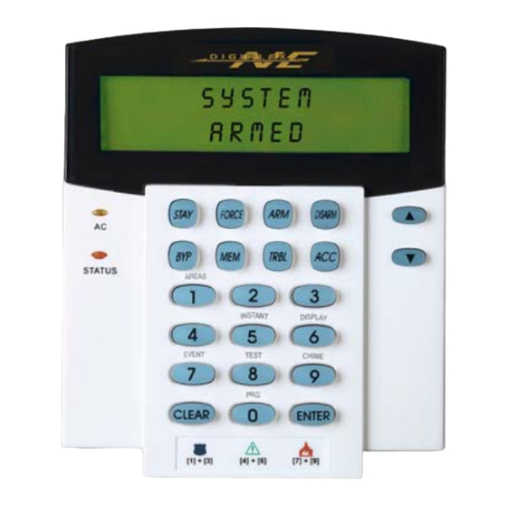
- Page 1 DGP-641 LCD Keypad (V1.3) DGP-641ACC Access Control LCD Keypad (V1.1) Reference and Installation Manual...
-
Page 3: Table Of Contents
TABLE OF CONTENTS 1.0 Introduction ............4 1.1 S ............5 PECIFICATIONS 2.0 Installation............6 2.1 C ........6 ONNECTING THE EYPAD 2.2 C ........6 ONNECTING EYPAD ONES 2.3 P ......... 7 ROGRAMMABLE UTPUT 3.0 Programming ..........11 3.1 E .... - Page 4 4.9 B ..........17 EEP ON ROUBL E 4.10 K ........18 EYPAD AMPER NABLE 5.0 Features For DGP-641 Only......19 5.1 C ........19 ONF IDENT IAL IMER 5.2 PGM S ............19 TATE 5.3 PGM A ........20...
-
Page 5: Message Programming
6.5 D ........28 PTIONS 6.5.1 Door Left Open Access Alarm ......... 28 6.5.2 Door Left Open Interval Before Access Alarm ..29 6.5.3 Door Left Open Pre-Alarm ........29 6.5.4 Door Left Open Pre-Alarm Timer ......29 6.5.5 Door Left Open Alarm Feedback ......30 6.5.6 Beep Timer For Door Left Open Alarm .... -
Page 6: Introduction
1.0 INTRODUCTION ® Thank you for choosing Paradox Security Systems. The Digiplex™ Security System is an advanced technology security system that will provide reliable security protection and powerful features that are easy to use. The elegant and user-friendly Digiplex™ LCD Keypad will allow easy access to the security system's functions and information at the touch of a button. -
Page 7: Specifications
1.1 S PECIFICATIONS Power input: 9-16 VDC, 80mA maximum PGM current limit: 50 mA Number of inputs: 1 (DGP-641) 2 (DGP-641ACC) Power indication: Yellow LED on Locate indication: Green and yellow LEDs flash simultaneously Bus fault indication: Red and yellow LEDs flash alternately... -
Page 8: Installation
2.1 C ONNECTING THE EYPAD The Digiplex™ LCD keypads (DGP-641 and DGP-641ACC) are connected to the control panel's bus in a star and/or daisy chain configuration. This 4-wire communication bus provides power and two-way communication between the control panel and all modules connected to it. -
Page 9: Programmable Output
the keypad. For example, a door contact located at the entry point of an establishment can be wired directly to the input terminal of the entry point keypad instead of wiring the door contact all the way to the control panel. Connect the device to the keypad's input terminal as shown in Figure 1 on page8. - Page 10 Figure 1: Connecting the Keypad and Keypad Zone 8 Installer’s Guide...
- Page 11 Figure 2: Typical Access Control Installation (DGP-641ACC) Figure 3: Access Control Overview (DGP-641ACC Only) Digiplex LCD Keypad...
- Page 12 Figure 4: Access Control Connections (DGP-641ACC Only) 10 Installer’s Guide...
-
Page 13: Programming
3.0 PROGRAMMING Programming the DGP-641 or DGP-641ACC LCD keypads is simple. Enter the “Module Programming Mode”, enter the desired section followed required data. When programming the keypad, use the keypad’s Programming Guide to keep track of which sections were programmed and how. We strongly recommend you read this entire manual before you begin programming. -
Page 14: Rogramming Et Hods
serial number is located on the keypad's PC board or enter section [000] in Step 3 to view the keypad’s serial number. 3.2 P ROGRAMMING ETHODS 3.2.1 Feature Select Programming Program sections [001] to [005] by enabling or disabling options. Within the sections, numbers from [1] to [8] represent a specific keypad option. - Page 15 source’s data. If you want to program more than one keypad with the source’s data, enter the serial numbers of the keypads one at a time. Step 6: Once you have entered the serial numbers of the keypads you want to program, press the [ ] key.
-
Page 16: System Options
4.0 SYSTEM OPTIONS 4.1 P ARTITION SSIGNMENT Section 001: Options [1] to [4] Each keypad in the Digiplex system can be assigned to one or more partitions. In section [001], options [1] to [4] represent partitions 1 through 4 respectively. To assign the keypad to a partition, simply enable the option that corresponds to the desired partition. -
Page 17: Display Entry Delay Timer
Figure 5 (page 16) and the “AC” and “STATUS” LED will be off until either a button is pressed or an access code is entered. For the DGP-641 keypad, the period of time in which no action is performed is defined by the Confidential Mode Timer (005-255 seconds;... -
Page 18: Muting
every area the keypad is assigned, the Alarm Memory Display if necessary, and the Trouble Display if necessary (see Digiplex User Manual) will also scroll on the LCD screen. Section [002]: Option [4] OFF= Normal Mode (default) Option [4] ON = Confidential Mode Option [5] OFF= LCD screen activated by entering an access code (default) Option [5] ON = LCD screen activated by pressing a button... -
Page 19: Beep On Exit Delay
4.7 B EEP ON ELAY Section 003: Option [2] The keypad can beep once every second during the Exit Delay Timer. During the final 10 seconds, it will beep more rapidly to provide a final warning before the area is armed. Option [2] OFF= Exit Delay beep disabled Option [2] ON = Exit Delay beep enabled (default) 4.8 C... -
Page 20: Keypad Tamper Enable
see the Digiplex Control Panel’s Reference and Installation Manual. The intermittent beep will be re-initialized whenever the trouble condition re-occurs. Option [1] OFF= Beep disabled: System Troubles and Clock Loss (default) Option [1] ON = Beep enabled: System Troubles and Clock Loss Option [2] OFF= Beep disabled: Communicator Troubles (default) Option [2] ON = Beep enabled: Communicator Troubles Option [3] OFF= Beep disabled: Module and Bus Troubles (default) -
Page 21: Features For Dgp-641 Only
5.0 FEATURES FOR DGP-641 ONLY 5.1 C ONFIDENTIAL IMER Section 006 (Default: 120 seconds) Section [006] determines the amount of time without action before the keypad enters Confidential Mode. For more information on Confidential Mode, refer to “Confidential Mode” on page15. -
Page 22: Pgm Activation Event
5.3 PGM A CTIVATION VENT Section 008 The PGM Activation Event determines which event(s) will activate the keypad's on-board PGM. For details on the available activation events, refer to the PGM Programming Table in the Digiplex Programming Guide. 6) In section [008], key in the first digit where each digit from 8 to F represents an event group (0 = PGM Disabled). -
Page 23: Pgm Timed Mode
the same manner as the PGM Activation Event. 5.5 PGM T IMED Section 005: Option [2] If the keypad is in PGM Timed Mode, the keypad's on-board PGM will be deactivated according to the PGM Timer (see section 5.6 below) instead of the PGM Deactivation Event. Option [2] OFF= Deactivates on PGM Deactivation Event (default) Option [2] ON = PGM will deactivate according to the PGM Timer 5.6 PGM T... -
Page 24: Pgm Override
Option [3] ON = PGM Base Time is 1 minute 5.8 PGM O VERRIDE Section 005: Option [4] When PGM Override is enabled, the keypad's on-board PGM will ignore PGM Activation Events (section 5.3, page 20), PGM Deactivation Events (section 5.4, page 20), and PGM Timers (section 5.6, page21). -
Page 25: Features For Dgp-641Acc Only
6.0 FEATURES FOR DGP-641ACC ONLY 6.1 B OLTMETER The Bus Voltmeter provides a real-time display of the voltage so you can verify if the bus is supplying sufficient power at the keypad’s location. The readings will appear on the LCD screen. A reading of 9.2V indicates that the voltage is too low. -
Page 26: Reader S Options
partition, only Partition 2 will arm. Option [5] ON = door assigned to Partition 1(default) Option [6] ON = door assigned to Partition 2 Option [7] ON = door assigned to Partition 3 Option [8] ON = door assigned to Partition 4 = Access Control Cards will not be able to arm and/or disarm partitions from the door's reader. -
Page 27: Reader's Led Options Upon Access Granted
6.3.3 Reader's LED Options Upon Access Granted Section [005]: Option [7] When the Access Control card is presented to the reader, the reader's LED can be programmed to turn green during the door’s unlocked period (or until the door closes) or extinguish briefly to indicate that the door is unlocked. -
Page 28: Door Unlocked Period Extension
6.4.3 Door Unlocked Period Extension Section [007] The Door Unlocked Period Extension is the amount of time added to the Door Unlocked Period in section [006], which leaves the door unlatched longer. This will allow those with this feature enabled on their User Access Codes extra time to enter, which may be useful for the physically challenged or for seniors. -
Page 29: Card Activates Door Unlocked Schedule
programmed with “H”, users will have access during the days programmed in the sections [381] to [392]. Program the Start Time and End Time according to the 24-hour clock within the same day. Use Feature Select Programming to set the options representing the Days. Option Day Option Day Sunday (S) -
Page 30: Door Left Open Options
presented to the reader at 8AM on Monday. Although the schedule started at 7AM, the door remained locked from 7AM to 8AM. Once access was granted at 8AM, the door remained unlocked until 5PM. Option [1] ON = Card activates Door Unlocked Schedule Option [1] OFF= The Schedule activates without Card (default) 6.5 D PTIONS... -
Page 31: Door Left Open Interval Before Access Alarm
6.5.2 Door Left Open Interval Before Access Alarm Section [008] The Door Left Open Interval is the time that a door can remain open after an Access Granted or a Request for Exit without generating an Access Alarm. Enter any value between 001 and 255 to determine the number of seconds the door may remain open before the Access Alarm is triggered. -
Page 32: Door Left Open Alarm Feedback
open for 45 seconds. Enter any value between 001 and 255 to determine the seconds before the expiry of the Door Left Open Interval that the reader will beep. (default = 15 seconds) Figure 9: Pre-Alarm example 6.5.5 Door Left Open Alarm Feedback Section [003]: Options [5] and [6] An Access Control door is programmed with a Door Left Open Interval (see section 6.5.2 on page 29). -
Page 33: Beep Timer For Door Left Open Alarm
Option [6] OFF= beep as long as the Door Left Open Alarm is occurring (default) 6.5.6 Beep Timer For Door Left Open Alarm Section [010] This Beep Timer determines the amount of time the Door Left Open Alarm will beep. Once the Door Left Open Interval (see section 6.5.2 on page 29) has expired, the Door Left Open Alarm (see section 6.5.5 on page 30) will be triggered. -
Page 34: Door Forced Open Feedback
Section [003] Option [7] Door Forced Open Alarm (audible/silent) Option [6] Door Forced Open Alarm follows (restore/timer) [011] Beep Timer for Door Forced Open Alarm 6.6.2 Door Forced Open Feedback Section [003]: Options [7] and [8] The Access Alarm can be either audible or silent and will either beep as long as the Access Alarm is occurring or follow the Beep Timer in section [011]. -
Page 35: Message Programming
Each section from [101] to [249] contains one message with a maximum of 16 characters. For more details and to record any changes, use the DGP-641 LCD Programming Guide. Section [101] to [148] = Zone 01 to Zone 48 respectively... - Page 36 ] - Insert Space STAY Pressing the [ ] key inserts a blank space in the current cursor position. STAY ] - Delete FORCE Pressing the [ ] key will delete the character or blank space FORCE found at the current cursor position. ] - Delete Until the End Pressing the [ ] key will delete all characters and spaces to the...
- Page 37 Table 2: Special Characters Catalog Digiplex LCD Keypad...
-
Page 38: Glossary
8.0 GLOSSARY Access Alarm: An audible or silent warning generated by the reader to indicate that a protected door has not closed within the programmed time allowed or that a protected door was opened without an “Access Granted” or “Request for Exit” signal. If the Access Alarm is programmed to be audible, the reader assigned to the door can beep. - Page 39 Digiplex Alarm System has been breached. This event is logged in the Event Buffer and can be reported to a Monitoring Station. Door Left Open: Each Access Control door is programmed with a period of time it is allowed to remain open. Once the door has been open past this time limit, an Access Alarm will be triggered (see Access Alarm).
- Page 40 Holidays: Days programmed in sections [381] to [392] that are not considered normal work days, such as legal, religious, and feast days. Pre-Alarm: A beep tone warning that an Access Alarm will be generated if a protected door is not closed within a specified period.
- Page 41 Warranty The Seller warrants its products to be free from defects in materials and workmanship under normal use for a period of one year. Except as specifically stated herein, all express or implied warranties whatsoever, statutory or otherwise, including without limitation, any implied warranty of merchantability and fitness for a particular purpose, are expressly excluded.
Need help?
Do you have a question about the digiplex DGP-641 and is the answer not in the manual?
Questions and answers