
Related Manuals for TTI CPX200


Summary of Contents for TTI CPX200
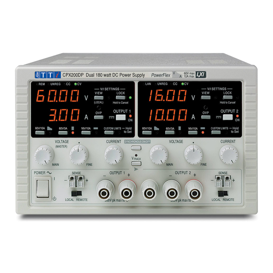
- Page 1 CPX200 Dual 35V 10A Power Supply Service Manual Book Part Number 48511-0270 - Issue 1...
-
Page 2: Table Of Contents
Table of Contents Specifications Safety General Circuit Descriptions Calibration Parts List Component Layouts Circuit Diagrams... -
Page 3: Specifications
Specifications OUTPUT SPECIFICATIONS Voltage Range: 0V to 35V Current Range: 0A to 10A Power Range: Up to 175W Output Voltage Setting: By coarse and fine controls. Output Current Setting: By single logarithmic control. Operating Mode: Constant voltage or constant current with automatic cross-over provided that the power demanded stays within the power envelope, see graph. - Page 4 METER SPECIFICATIONS Meter Types: Dual 4 digit meters with 12.5mm (0.5") LEDs. Reading rate 4 Hz. Meter Resolutions: 10mV, 10mA Meter Accuracies: Voltage 0.2% of reading +/-1 digit, Current 0.5% of reading +/-1 digit GENERAL AC Input: 230V AC ± 14%, 50/60Hz. Installation Category II. Power Consumption: 600VA max.
-
Page 5: Safety
Safety This power supply is a Safety Class I instrument according to IEC classification and has been designed to meet the requirements of EN61010-1 (Safety Requirements for Electrical Equipment for Measurement, Control and Laboratory Use). It is an Installation Category II instrument intended for operation from a normal single phase supply. -
Page 6: Emc
This power supply has been designed to meet the requirements of the EMC Directive 89/336/EEC. Compliance was demonstrated by meeting the test limits of the following standards: Emissions EN50081-1 (1992) Generic emission standard for residential commercial and light industry. Test methods and limits used were: a) EN55022 Conducted, Class B b) EN55022 Radiated, Class B Immunity... -
Page 7: General
General Service Handling Precautions Service work or calibration should only be carried out by skilled engineers using high quality test equipment. If the user is in any doubt as to his competence to carry out the work, the instrument should be returned to the manufacturer or their agent overseas for the work to be carried out. The tracks on the printed circuit boards are very fine and may lift if subjected to excessive heat. -
Page 8: Circuit Descriptions
Circuit Descriptions The two outputs are identical with the exception of slight layout variations; only one output (Channel A) is therefore described. Component positions on the other output (Channel B) are numbered from 101 upwards, e.g. C22 on Channel A described is C122 on Channel B. Power Section The power section is contained entirely on the main (lower) board;... - Page 9 the secondary. When Q1 and Q2 are turned off the voltage across the primary will reverse and generally bring diodes D1 and D2 into conduction; D1, D2 provide clamp protection against overvoltage caused by leakage inductance in the transformer, so protecting the FETs. At the same time the secondary e.m.f.
-
Page 10: Control Section
Control Section The control circuitry is contained entirely on the control (upper) board with the exception of the current transformer (T2) which is fitted on the main board and the user controls themselves which are on the front panel board. Voltage Control Loop The feedback voltage for the voltage control loop is fed from the main board via PJ4 pin 5 (+SENSE A) and PJ4 pin 8 (-SENSE A);... - Page 11 Primary Current Control and Primary Current Limit The primary current is sensed by transformer T2 on the main board; the primary is in series with T1 and the secondary is fed to D2/R2 on the control board via PJ5 pins 1 and 2. D2 rectifies the signal which appears as a voltage across R2 in parallel with VR5/R22;...
- Page 12 The +2·45V reference line VREF+A is derived from reference diode D23 attenuated to about 188mV by divider R83, R82 at the reference input of analogue to digital converter IC12, yielding a sensitivity of about 92uV per digit. The set current signal ISETA is taken from the VR4 wiper on the front panel board via PJ8 pin 2 and on to the ADC as IPROGA, via adjustable attenuating chain R92, VR3, R93, for display of the preset current level.
-
Page 13: Calibration
Calibration Refer to the General section for dismantling instructions and safety precautions. Component numbers are given for Channel A/Channel B, e.g. VR1/VR101, where VR1 refers to Channel A and VR101 to Channel B. Channel A is marked as Output 1 on the front panel, Channel B as Output 2. - Page 14 Differential Gain Adjustment Remove the link between the –OUTPUT and –SENSE terminals and fit a diode, anode to –SENSE and cathode to –OUTPUT; connect a small switch across the diode. Leave the link in place between +OUTPUT and +SENSE and connect a 15kΩ resistor between +OUTPUT and –SENSE.
-
Page 15: Parts List
Parts List PCB ASSY FRONT PANEL - (44115-0820) Part Number Description Position 22226-0140 KEYSWITCH DARK GREY K1,2,101,102 22573-0056 HEADER 16 WAY STR SIL FOR DISPLAYS 23202-0270 RES 27R0F W25 MF 50PPM R1-8,101-108 23202-1910 RES 910RF W25 MF 50PPM R21,121 23202-2150 RES 1K50F W25 MF 50PPM R17,18,38,39,117,118,138,139 23202-3100... - Page 16 PCB ASSY CNTL – (44115-0810) continued/..Part No. Position Description 22575-0062 HEADER 10 WAY (2X5) STR PJ4,104 22575-0064 HEADER 26 WAY (2X13) STR PJ8,108 23185-0000 RES ZERO OHM LK2,7,8,102,107,108 23189-0560 RES 56RJ 1W6 500PPM TYPE PR37 R2,102 23190-1100 RES 100RJ 2W5 500PPM TYPE PR52 R15,115 23202-0220 RES 22R0F W25 MF 50PPM...
- Page 17 PCB ASSY CNTL - (44115-0810) continued/... Part No. Position Description 23202-4100 RES 100KF W25 MF R18,19,86,87,118,119,186,187 23202-4120 RES 120KF W25 MF 50PPM R83,183 23202-4160 RES 160KF W25 MF 50PPM R53,153 23202-4200 RES 200KF W25 MF 50PPM R34,88,134,188 23202-4750 RES 750KF W25 MF 50PPM R14,114 23202-4820 RES 820KF W25 MF 50PPM...
- Page 18 Part No. Position Description 23685-0002 CAP 1N0J 100V P/P C4,104 23685-0007 CAP 100NK 160V P/P P10 C45,145 25021-0901 DIO 1N4148 B/R D1,2,3,5,6,8,9,11-17,24,101,102,103,105, 106,108,109, 111-117,124 25115-0907 DIO 1N4002 B/R D7,10,107,110 25130-0903 DIO ZEN 5V1 W4 D4,104 25211-9302 RECTIFIER BRIDGE W02G BR1,101 25336-5590 TRAN PNP BC559C Q3,103...
- Page 19 PCB ASSY - MAIN (44115-0800) continued/... Part No. Position Description 20611-0003 BUSH POLYESTER TO220 J22-5006 FOR D3,4,103,104 20613-0012 WASHER NON-INSULATING FOR Q1,2,101,102 20613-9401 WASHER TO220 ADHESIVE FOR D3,4,103,104 20661-0225 SPACER Hex M3 x 12ZPST FOR PCB 20661-0408 SPACER Rnd/Hex/ST 2.5 L MAIN/CONTROL PCBS 20670-0135 CLIP GP02 FOR PCB MTG H/SINKS...
- Page 20 Part No. Position Description 23209-5100 RES 1M00F W75 MF 100PPM 23296-0020 RES 0R01D 4 TERM 30PPM PBV R14,114 23379-1100 RES PS/H 100R Cermet 10MM VR1,101 23386-0010 VARISTOR V275LA20A VDR1 23386-0030 THERMISTOR - INRUSH LIMITER 4A 23388-0030 THERMISTOR PTC 2322.661.15693 PTC1,2,101,102 23424-0459 CAP 4N7 250V AC CER Y RATED C6,7...
- Page 21 20213-0010 CAPTIVE NUT SNU-1219-17-00 20234-0029 SCREW M4 X 12 PNHDPZ ZPST TRANSFORMER 20236-0010 SCREW M4 X 12 TAMPERPROOF EARTH 22115-0260 TRANSFORMER - CPX200 22575-0204 SKT4W .156 20AWG IDT 22575-0205 SKT5W .156 20AWG IDT PJ7,107 22575-0207 SKT7W .156 20AWG IDT PJ1A...
- Page 22 Part Number Description Position 20030-0266 WASHER M4 ZPST RUBBER FEET 20037-0301 WASHER M3 SHK/PROOF I/T ZPST FRONT PANEL, EARTH 20038-9501 WASHER M3 Spring PCB PILLARS, STUDS 20062-0700 SCREW NO 6 X 3/8 RFLNGPZ ST/AB R.PANEL/CHASSIS 20062-9303 SCREW NO 6x0.5in. PNHDPZ ST/AB CONTROL TO MAIN PILLARS 20063-0010 SCREW NO6 X 3/8 NIB HDPZ ST/AB...
-
Page 23: Component Layouts
Component Layouts FRONT PANEL PCB... - Page 24 CONTROL PCB...
- Page 25 MAIN PCB...
-
Page 26: Circuit Diagrams
Circuit Diagrams... - Page 27 CONTROL PCB (PART) - CHANNEL A (CHANNEL B IDENTICAL)
- Page 28 CONTROL PCB (PART) - CHANNEL A (CHANNEL B IDENTICAL)
- Page 29 MAIN(POWER) PCB...
- Page 30 Thurlby Thandar Instruments Ltd Glebe Road, Huntingdon, Cambridgeshire PE29 7DR, England Telephone: (44) 01480 412451 Fax: (44) 01480 450409 e mail: sales@tti-test.com web site: www.tti-test.com...
Need help?
Do you have a question about the CPX200 and is the answer not in the manual?
Questions and answers