
Subscribe to Our Youtube Channel
Related Manuals for TTI EL Series


Summary of Contents for TTI EL Series
- Page 1 THURLBY THANDAR INSTRUMENTS EL SERIES ( EL302Tv) including LINEAR BENCH POWER SUPPLIES INSTRUCTION MANUAL...
-
Page 2: Table Of Contents
Table of Contents Introduction Specification Safety Installation Operation - Main Outputs Operation – Auxiliary Output Operation - General Maintenance Instructions en Francais Sécurité Installation Fonctionnement - Sorties principales Fonctionnement - Sortie logique Fonctionnement - Généralités Maintenance Bedienungsanleitung auf Deutsch Sicherheit Installation Betrieb - Hauptausgänge Betrieb - Logik-Ausgang... -
Page 3: Introduction
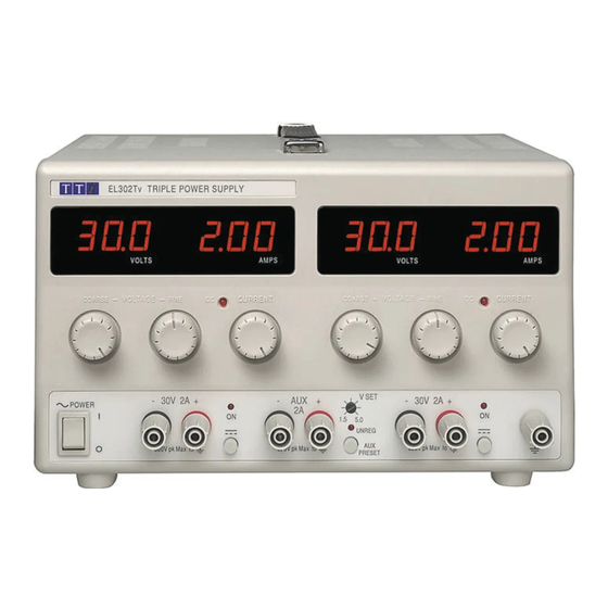
Introduction The EL series provides medium levels of power (up to 125 watts) in a compact and attractive case style using linear regulation. High resolution controls allow precise setting of voltage and current levels which are indicated on accurate and highly legible digital meters. - Page 4 Line Regulation: <0.01% of maximum output for 10% line change. Ripple & Noise: Typically <1mVrms (CV mode). (20MHz bandwidth) Transient Load Response: <20µs to within 50mV of set level for 90% load change. Temperature Coefficient: Typically <100ppm/°C. Status Indication: Output on lamp. Constant current mode lamp. METER SPECIFICATIONS (Main Outputs) Meter Types: Dual 3 digit meters with 14mm (0.56") LEDs.
-
Page 5: Ec Declaration Of Conformity
EC Declaration of Conformity Thurlby Thandar Instruments Ltd Glebe Road Huntingdon Cambridgeshire PE29 7DR England declare that the EL155, EL183, EL301, EL302, EL303, EL561, EL302D and EL302Tv, Bench Power Supplies meet the intent of the EMC Directive 2004/108/EC and the Low Voltage Directive 2006/95/EC. Compliance was demonstrated by conformance to the following specifications which have been listed in the Official Journal of the European Communities. -
Page 6: Emc
This instrument has been designed to meet the requirements of the EMC Directive 2004/108/EC. Compliance was demonstrated by meeting the test limits of the following standards: Emissions EN61326 (1998) EMC product standard for Electrical Equipment for Measurement, Control and Laboratory Use. Test limits used were: Radiated: Class B Conducted: Class B... -
Page 7: Safety
Safety This power supply is a Safety Class I instrument according to IEC classification and has been designed to meet the requirements of EN61010-1 (Safety Requirements for Electrical Equipment for Measurement, Control and Laboratory Use). It is an Installation Category II instrument intended for operation from a normal single phase supply. -
Page 8: Installation
Installation Mains Operating Voltage Check that the instrument operating voltage marked on the rear panel is suitable for the local supply. Should it be necessary to change the operating voltage, proceed as follows: Ensure that the instrument is disconnected from the AC supply. Remove the screws holding the case upper and handle and lift off the case upper. -
Page 9: Operation - Main Outputs
Operation - Main Outputs Setting Up the Output With the POWER switch on ( ) and the output OFF the output voltage and current limit can be accurately preset using the VOLTAGE and CURRENT controls; the left-hand meter shows the set voltage and the right-hand meter shows the set maximum current. -
Page 10: Operation - Auxiliary Output
Operation – Auxiliary Output Output Voltage The output voltage can be set between 1.5V and 5.0V using the front panel rotary adjustment beside the centre terminals. With the right-hand main output OFF, pressing the SHOW AUX PRESET button will display the AUX output voltage and current limit on the right-hand meters. Current Limit The output will go into current limit above 2A;... -
Page 11: Maintenance
Maintenance The Manufacturers or their agents overseas will provide repair for any unit developing a fault. Where owners wish to undertake their own maintenance work, this should only be done by skilled personnel in conjunction with the service manual which may be purchased directly from the Manufacturers or their agents overseas. -
Page 12: Sécurité
Sécurité Cet instrument est de Classe de sécurité 1 suivant la classification IEC et il a été construit pour satisfaire aux impératifs EN61010-1 (impératifs de sécurité pour le matériel électrique en vue de mesure, commande et utilisation en laboratoire). Il s'agit d'un instrument d'installation Catégorie II devant être exploité... -
Page 13: Installation
Installation Tension d’utilisation secteur Vérifier que la tension opérationnelle de l'instrument indiquée sur le panneau arrière est appropriée pour l'alimentation locale. S'il s'avère nécessaire de modifier la tension opérationnelle, procéder de la manière décrite ci-dessous: S'assurer que l'instrument est débranché de l'alimentation c.a. Enlever les vis de retenue de la partie supérieure du boîtier et de la manette et soulever la partie supérieure du boîtier. -
Page 14: Fonctionnement - Sorties Principales
Fonctionnement - Sorties principales Réglage de la sortie Lorsque l’interrupteur POWER (alimentation) est en position ( ) et la sortie est en position OFF (éteinte), il est possible de régler avec précision la limite de tension et de courant de sortie au moyen des commandes VOLTAGE (Tension) et CURRENT (Courant);... -
Page 15: Fonctionnement - Sortie Auxiliaire
Fonctionnement – Sortie Auxiliaire Tension de sortie La tension de sortie peut être réglée entre 1.5V et 5.0V en utilisant la commande rotative du panneau avant près des bornes centrales. Avec l'afficheur de l'état de la sortie principale droite, un appui sur le bouton SHOW AUX PRESET (montrer les réglages auxiliaire) provoquera l'affichage de la tension et de la limite du courant de la sortie auxiliaire sur l'afficheur droit. -
Page 16: Maintenance
Maintenance Le Constructeur ou ses agents à l'étranger répareront tout bloc qui tombe en panne. Si le propriétaire de l'appareil décide d'effectuer lui-même la maintenance, ceci doit uniquement être effectué par un personnel spécialisé qui doit se référer au manuel d’entretien que l'on peut se procurer directement auprès du Constructeur ou de ses agents à... -
Page 17: Sicherheit
Sicherheit Dieses Gerät wurde nach der Sicherheitsklasse (Schutzart) I der IEC-Klassifikation und gemäß den europäischen Vorschriften EN61010-1 (Sicherheitsvorschriften für elektrische Mess-, Steuer-, Regel- und Laboranlagen) entwickelt. Es handelt sich um ein Gerät der Installationskategorie II, das für den Betrieb von einer normalen einphasigen Versorgung vorgesehen ist. -
Page 18: Installation
Installation Netzbetriebsspannung Sicherstellen, daß die auf der Geräterückwand angegebene Betriebsspannung mit der Versorgungsspannung am Ort übereinstimmt. Falls es erforderlich ist, die Betriebsspannung zu ändern, wie folgt vorgehen: Sicherstellen, daß das Gerät vom Wechselstromnetz getrennt ist. Schrauben entfernen, mit denen die obere Gehäusehälfte und der Handgriff befestigt sind und obere Gehäusehälfte abheben. -
Page 19: Betrieb - Hauptausgänge
Betrieb - Hauptausgänge Einstellung des Ausgangs Bei eingeschaltetem POWER (Netzschalter I) und ausgeschaltetem Ausgang läßt sich die Ausgangsspannung und Strombegrenzung mit Hilfe der Knöpfe VOLTAGE (Spannung) und CURRENT (Strom) genau voreinstellen. Die linke Anzeige zeigt die eingestellte Spannung und die rechte den eingestellten Maximalstrom an. Ist der Ausgangsschalter aktiviert, leuchtet die ON (Ein)-Leuchte auf. -
Page 20: Betrieb - Hilfsausgang
Betrieb – Hilfsausgang Ausgangsspannung Die Ausgangspannung kann mittels Drehkopf, neben den zentralen Anschlussklemmen, in einem Bereich von 1,5 V bis 5,0 V eingestellt werden. Ist der rechte Hauptausgang ausgeschaltet, kann durch drücken der SHOW AUX PRESET Taste die eingestellte Spannung und Strombegrenzung für den Hilfsausgang in den beiden rechten Anzeigen zu Ansicht gebracht werden. -
Page 21: Wartung
Wartung Die Hersteller bzw. deren Vertretungen im Ausland bieten die Reparatur von Geräten an, bei denen eine Störung aufgetreten ist. Wenn der Eigentümer die Wartungsarbeiten selbst durchführen möchte, hat er dafür Sorge zu tragen, daß diese Arbeiten ausschließlich von entsprechend qualifiziertem Personal und gemäß Wartungshandbuch ausgeführt werden, das direkt von den Herstellern oder deren Vertretungen im Ausland bezogen werden kann. -
Page 22: Sicurezza
Sicurezza Questo strumento appartiene alla Categoria di Sicurezza 1, secondo la classifica IEC, ed è stato progettato in modo da soddisfare i criteri EN61010-1 (requisiti di Sicurezza per Apparecchiature di misura, controllo e per uso in laboratorio). È uno strumento di Categoria d’installazione II ed è inteso per il funzionamento con un’alimentazione normale monofase. -
Page 23: Installazione
Installazione Tensione d’esercizio Controllare che la tensione d’esercizio dello strumento segnata sul pannello posteriore sia uguale a quella della rete elettrica locale. Se dovesse rendersi necessario cambiare la tensione d'esercizio, osservare il seguente procedimento: Controllare che lo strumento sia scollegato dall'alimentazione a c.a. Togliere le viti che fissano il coperchio superiore e la maniglia e sollevare il coperchio superiore. -
Page 24: Funzionamento - Uscite Principali
Funzionamento - Uscite principali Impostazione dell’uscita Con il commutatore POWER (alimentazione) impostato su ( I ) e l’uscita in posizione OFF, le uscite in tensione e corrente possono essere impostate in maniera accurata utilizzando i le manopole VOLTAGE (tensione) e CURRENT (corrente); il misuratore di sinistra mostra la tensione impostata mentre quello di destra indica la corrente massima impostata. -
Page 25: Funzionamento - Uscita Ausiliaria
Funzionamento – Uscita Ausiliaria Tensione di uscita La tensione di uscita può essere regolata tra 1.5V e 5.0V usando il potenziometro a fianco dei terminali posti al centro de pannello frontale.Impostando in OFF l’uscite di destra, premendo il pulsante “SHOW AUX PRESET” verrà visualizzata la tensione e la corrente dell’uscita ausiliaria sugli indicatori posti a destra. -
Page 26: Manutenzione
Manutenzione I Produttori o i loro agenti all’estero faranno le riparazioni necessarie in caso di guasto. Qualora l’utente desiderasse eseguire il lavoro di manutenzione, tale lavoro deve essere fatto solo da personale qualificato e usando il manuale di servizio che può essere acquistato direttamente dai Produttori o dai loro agenti all’estero. -
Page 27: Seguridad
Seguridad Este es un instrumento de Clase de Seguridad I según la clasificación del IEC y ha sido diseñado para cumplir con los requisitos del EN61010-1 (Requisitos de Seguridad para Equipos Eléctricos para la Medición, Control y Uso en Laboratorio). Es un equipo de Categoría II que debe ser usado con un suministro monofásico normal. -
Page 28: Instalación
Instalación Tensión de la Red Eléctrica Verificar que la tensión de funcionamiento del instrumento que figura en el panel trasero concuerde con el suministro local. Si fuese necesario cambiar la gama de tensiones de functionamiento, proceda de la siguiente manera: Cerciorarse de que el instrumento esté... -
Page 29: Operación - Salidas Principales
Operación - Salidas principales Reglaje de la salida Con el interruptor de alimentación en ON (I) y la salida OFF de la tensión de salida y el límite de corriente con precisión usando los controles de VOLTAGE y CURRENT; el medidor a la izquierda indica la tensión ajustada y el medidor a la derecha indica la corriente máxima preajustada. -
Page 30: Operación - Salida Auxiliar
Operación – Salida Auxiliar Tensión de Salida La salida de voltaje puede ajustarse entre 1.5V y 5.0V mediante el botón giratorio del panel frontal al lado de los terminales centrales. Con el interruptor a la derecha de la salida principal en OFF, pulsando el botón SHOW AUX PRESET se visualizará... -
Page 31: Mantenimiento
Mantenimiento Los fabricantes o sus agentes en el extranjero ofrecen un servicio de reparación para toda unidad que desarrolle un defecto. Si los propietarios desearan establecer su propio servicio, esto sólo debe realizarse por personas cualificadas en conjunto con el manual de servicio que puede adquirirse directamente del Fabricante o de sus agentes en el extranjero. - Page 32 Thurlby Thandar Instruments Ltd Glebe Road, Huntingdon, Cambridgeshire PE29 7DR, England Telephone: 44 (0)1480 412451 Fax: 44 (0)1480 450409 International website: www.tti-test.com UK website: www.tti.co.uk e mail: sales@tti-test.com Book Part No. 48511-0960 Issue 3...
Need help?
Do you have a question about the EL Series and is the answer not in the manual?
Questions and answers