Table of Contents
Advertisement
Advertisement
Table of Contents

Related Manuals for TTI QPX1200


Summary of Contents for TTI QPX1200
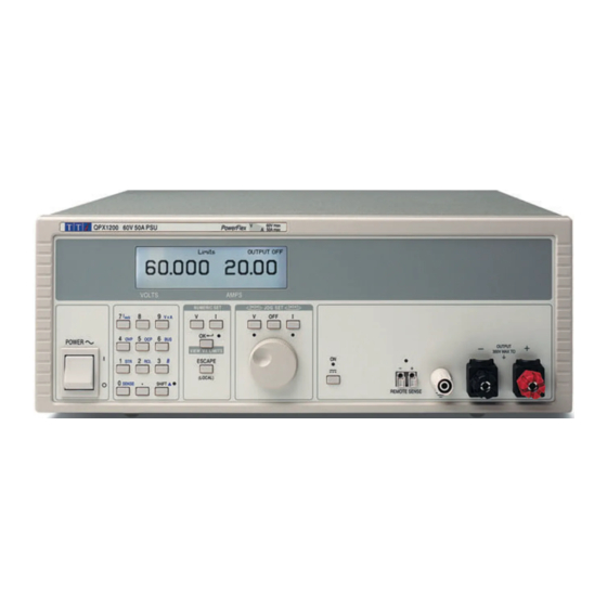
- Page 1 QPX1200 DC Power Supply Service Manual Manual Part Number 48511-1130 Issue 1...
-
Page 2: Table Of Contents
Table of Contents Specification Safety General Circuit Descriptions Calibration Procedure Parts List Component Layouts Circuit Diagrams... -
Page 3: Specification
Specification General specifications apply for the temperature range 5°C to 40°C. Accuracy specifications apply for the temperature range 18°C to 28°C after 1 hour warm-up with no load and calibration at 23°C. Typical specifications are determined by design and are not guaranteed. OUTPUT SPECIFICATIONS Voltage Range: 0V to 60V... - Page 4 Over-voltage Protection Range 2V to 65V. Resolution 0.1V; accuracy: 0.2% ± 0.2V. (OVP): Response time typically 100µs. Over-current Protection Range 2A to 55A. Resolution 0.1A; accuracy: 0.5% ± 0.2A. (OCP): Response time typically 100ms. Over-temperature Protection: The output will be tripped off if a fault causes the internal temperature to rise excessively.
- Page 5 INTERFACES Full digital remote control facilities are available through the RS232 and USB interfaces. Setting and readback resolutions are the same as the Output and Meter specifications respectively. RS232: Variable Baud rate, 19200 Baud maximum. 9-pin D-connector. Single instrument or Addressable RS232 operation. USB: Standard USB 2.0 hardware connection.
-
Page 6: Emc
This instrument has been designed to meet the requirements of the EMC Directive 89/336/EEC. Compliance was demonstrated by meeting the test limits of the following standards: Emissions EN61326 (1998) EMC product standard for Electrical Equipment for Measurement, Control and Laboratory Use. Test limits used were: Radiated: Class A Conducted: Class A... -
Page 7: Safety
Safety This power supply is a Safety Class I instrument according to IEC classification and has been designed to meet the requirements of EN61010-1 (Safety Requirements for Electrical Equipment for Measurement, Control and Laboratory Use). It is an Installation Category II instrument intended for operation from a normal single phase supply. -
Page 8: General
General Service Handling Precautions Service work or calibration should only be carried out by skilled engineers using high quality test equipment. If the user is in any doubt as to his competence to carry out the work, the instrument should be returned to the manufacturer or their agent overseas for the work to be carried out. The tracks on the printed circuit boards are very fine and may lift if subjected to excessive heat. - Page 9 Power: Remove the 10-way connector (PJ5) to the Control board, noting polarity (corner marker to pin1); remove the flat cable connection to PJ4 at the rear of the board; remove the HT connection from the PFC board at FAS1 & FAS2; remove the 4-way primary AUX connection from the PFC board at PJ1;...
-
Page 10: Circuit Descriptions
Circuit Descriptions PFC Board Mains Input, Filtering and Rectification The AC input is via PJ3, a pcb mounted IEC plug, and fuse FS1. X-capacitors C1, C4, C7, C10 & C68, together with the Y-capacitors C5, C6, C11 & C12, common mode inductors L1, L2 &... - Page 11 After a delay of about 0.4s, the voltage on C55, C56 exceeds the reference voltage on IC8-C negative input and the output of IC8-C goes high, turning on Q8 via D29 and R74 thus energising RL1 which bypasses the current inrush resistor R2. The output of IC8-C also charges C58 via R70 thus producing a short delay before the output of IC8-D goes high and turns on Q9 which in turn switches Q10 and Q11 off.
- Page 12 Boost Stage Three boost inductors L5, L6, L7 are each driven by a pair of MOSFETs Q3+Q6, Q2+Q5, Q1+Q4 respectively to raise the incoming, full wave rectified, sinusoidal mains voltage to a value some 30V higher than the peak of the maximum rms input voltage. This is achieved by storing energy in the boost inductors when the MOSFETs are conducting and transferring it to C19, C20 via boost diodes D5, D6, D33 when the MOSFETs are turned off.
- Page 13 voltage level at the positive input of op-amp IC14-A, the output of which turns on fan drive transistor Q38. The fan current is monitored by R120, R121 and amplified by IC14-B to provide negative feedback to the negative input of IC14-A. Secondary Side The main secondary winding is centre tapped and terminates on pins 19/20, 15/16 with the centre tap on 17/18.
- Page 14 The signal across the current sense resistors R12, R13, R14 and R15 is fed into pin5 of IC15-B. With the output current set to 20A, the signal at pin 5 is nulled by the current in R91/VR4 from the negative voltage generated by zener D49. The null point setting is aided by comparator IC15-A which drives two LEDs, the null being achieved when both LEDs are off .
-
Page 15: Control Board
Photograph 3 Photograph 4 Control Board The control board contains an ARM7 processor, IC111, programmed via JTAG header PJ103. The three processors communicate via a shared bus but in this case it is isolated via opto-couplers IC109 and IC110. The board needs several power supplies and, with the exception on the ‘-8V’ and ‘+15V’ rails, these are all derived from the ‘V+’... -
Page 16: Remote Sense
Demand Setting The voltage and current demands, together with OVP limit and the pseudo-analogue outputs are generated by a digital to analogue converter IC105 together with analogue switch IC106 and a series of sample and hold circuits. For each of the 5 channels the setting consists of a both a setting of a DAC reference and a value setting. - Page 17 Interface Board The interface board allows the unit to communicate externally via USB or RS232. IC5 is an ARM7 processor which is programmed in-circuit using the standard JTAG port accessed at PJ5. IC3 and IC6 generate the required supply rails. PJ3 provides an RS232 connection; IC1 and IC2 provide the necessary level shifting and inversion to convert the UART’s 5V ‘mark’...
-
Page 18: Calibration Procedure
Calibration Procedure The QPX1200 calibration menu can be found under extra functions “#99”. The output calibrations are dependent on the measurement being in calibration so it is recommended that each of the calibrations be done in the order they appear on the menu. - Page 19 07: Imon measurement calibration On the rear panel terminals short ‘Imonitor’ to ‘Icontrol’. Ensure that there is no load connected to the unit and connect the voltmeter from ‘Imonitor’ to ‘Common’. Select option 7 from the Calibration menu (Imon measurement) and press OK. The unit now gives an output of about 1 Amp; measure the voltage at ‘Imonitor’...
-
Page 20: Parts List
Parts List PCB ASSEMBLY - POWER - (44115-3060) Part Number Description Position 20205-0800 STUD M6 x 20 HFHB M6-20-X OUTPUT CONNECTION 20234-0023 SCREW M4 x 8 PNHDPZ ZPST HEATSINKS 20234-0100 SCREW M3 x 6PNHDPZ C/W EXT SH/P PCB SUPPORT SPACERS 20613-0007 SIL-PAD TO220 PLAIN FOR TH1... - Page 21 PCB ASSEMBLY - POWER - (44115-3060) /continued... Part Number Description Position 23210-0330 RES 33R0J 2W MF 250PPM 23210-1100 RES 100RJ 2W MF 250PPM R140 23210-1220 RES 220RJ 2W MF 250PPM R51, R141 23210-2470 RES 4K70J 2W MF 250PPM R127 23210-3470 RES 47K0J 2W MF 250PPM R131-132, R149-150 23215-2100...
- Page 22 PCB ASSEMBLY - POWER - (44115-3060) /continued... Part Number Description Position 23210-0330 RES 33R0J 2W MF 250PPM 25031-0100 DIO BAX12A D16-17, D22-23 25031-0150 DIO UF4006 25031-0250 DIO STTH6003CW D3, D6-7, D11 25130-0207 DIO ZEN 15V W4 D25-26, D36 25130-0231 DIO ZEN 8V2 W4 D37, D56 25130-0915 DIO ZEN 75V W4...
- Page 23 PCB ASSEMBLY SM POWER (44115-3061) /continued... Part Number Description Position 23105-2510 RES SM0805 5K10F W1 R66, R78 23105-3100 RES SM0805 10K0F W1 R9, R22, R53, R58, R61, R71, R82, R87, R89, R94, R96, R104-106, R109, R112-115, R124, R126, R146 23105-3200 RES SM0805 20K0F W1 R137 23105-3220...
- Page 24 PCB ASSEMBLY SM POWER (44115-3061) /continued... Part Number Description Position 27151-1030 IC SM AD633 27227-0130 IC SM 4013 27227-0690 IC SM 4069 27227-0810 IC SM 4081 IC10 27253-0140 IC SM MIC4428 IC11, IC13 35555-4690 PCB - POWER PCB ASSEMBLY CONTROL (44115-3180) Part Number Description Position...
- Page 25 PCB ASSEMBLY CONTROL (44115-3180) /continued... Part Number Description Position 25061-0201 LED - T1 ROUND(3MM) RED LED100 25117-0020 DIO 1N5401 D110 27001-0050 OPTO-COUPLER 6N136 IC109-110 27160-0009 IC V/REG 7805 IC117 27161-0060 IC V/REF LT1009 2.50V IC100 28500-0800 XTAL - 4.9152MHZ-MICROPROCSR X101 28502-0020 RESONATOR CERAMIC 12MHZ X100...
- Page 26 PCB ASSEMBLY SM CNTL (44115-3181) /continued... Part Number Description Position 23105-3200 RES SM0805 20K0F W1 R119 23105-3220 RES SM0805 22K0F W1 R163, R165 23105-3270 RES SM0805 27K0F W1 R217 23105-3470 RES SM0805 47K0F W1 R140-141, R191, R206, R212 23105-3680 RES SM0805 68K0F W1 R194, R197 23105-4100 RES SM0805 100KF W1...
- Page 27 PCB ASSEMBLY SM CNTL (44115-3181) /continued... Part Number Description Position 25603-0220 TRAN SM FET N FDV303N 25V Q112-113 27103-1010 IC SM LM339A QUAD IC107 27106-0644 IC SM TL074CD BI-FET OP-AMP IC103, IC108 27106-1110 IC SM LM358M DUAL OP AMP IC114 27106-1160 IC SM LM324M OP AMP IC115...
- Page 28 PCB ASSEMBLY – PFC (44115-3100) /continued... Part Number Description Position 22312-0250 FUSE CLIP 0.25in. PCB MTG 22315-0255 FUSE 15A HRC 1.25 X 0.25 FOR FS1 22455-0030 TAB 0.25in. STR PCB MTG W1-5 22455-0040 TAB 4.8MAX 0.8MM STR PCB MTG FAS5-6 22482-0020 BEAD, CERAMIC 11-54-3557-0 FOR R2, R52...
- Page 29 PCB ASSEMBLY – PFC (44115-3100) /continued... Part Number Description Position 23620-0267 CAP 100NK 100V P/E P5 C35, C35B 23620-0268 CAP 220NK400VP/E 468 SER P15 23684-0016 CAP 220NM 250VAC X2 P22.5 UL 23684-0023 CAP 2U2M 275VAC X2 P/P UL C1, C4, C7, C10, C15-16 23685-0013 CAP 330NK 160V/250V P/P P15 C18, C61-62...
- Page 30 PCB ASSEMBLY SM – PFC (44115-3101) /continued... Part Number Description Position 23105-4180 RES SM0805 180KF W1 R59-60, R59B, R60B 23105-4220 RES SM0805 220KF W1 R40-42, R70, R41B, R42B 23105-4330 RES SM0805 330KF W1 R34-35, R38-39, R34B, R35B, R38B, R39B 23105-4360 RES SM0805 360KF W1 23105-4430 RES SM0805 430KF W1...
- Page 31 PCB ASSEMBLY KEYBOARD (44115-3110) Part Number Description Position 20661-0282 SPACER Rnd 3.7 ID x 3.2 L Nyl LCD FIXING 20661-0872 SPACER TOWER RND 4.8ODx8L FOR LED1-5 22224-0020 ENCODER ROT 24 POSITION 22226-0101 KEYSWITCH - ALPS SKHHBW K1-20 22573-0048 HEADER 3WAY STR SIL STD/GOLD TP1-3 22573-0222 HEADER 2 WAY STR F/LOCK .156P...
- Page 32 PCB ASSEMBLY SM KEYBOARD (44115-3111) /continued... Part Number Description Position 23411-0475 CAP SM1206 4U7K 16V CER X7R C1-3, C11-12 23461-0020 CAP SM0805 100NZ 50V CER Y5V C16-17, C20-25 23461-0334 CAP SM0805 330NK 25V CER X7R C6-10 23559-2221 CAP SM 220U 10V AL ELEC C18-19 23559-4101 CAP SM 100U 25V AL ELEC...
- Page 33 PCB ASSEMBLY SM INTRFACE (44115-3151) Part Number Description Position 23105-0330 RES SM0805 33R0F W1 R3-4 23105-2100 RES SM0805 1K00F W1 R15, R19, R21 23105-2150 RES SM0805 1K50F W1 23105-2220 RES SM0805 2K20F W1 23105-3100 RES SM0805 10K0F W1 R1, R5-7, R10-14, R16-18, R25 23105-3470 RES SM0805 47K0F W1 R8-9...
- Page 34 MECHANICAL PARTS /continued... Part Number Description Position 20662-9101 INSTRUMENT FOOT BACK FEET 22040-0030 FERRITE SLEEVE APPX 8/16/14L SAFETY EARTH PFC TO POWER AUX MAINS TO FRONT PANEL (2) PFC TO KEYBOARD POWER TO CONTROL AUX 22040-0090 FERRITE SLEEVE 31x19IDx16L POWER TO FRONT TERMINALS FRONT TO REAR TERMINALS 22219-0140 SWITCH ROCKER DPDT 16A 250V...
- Page 35 FIXINGS & FASTNERS Part Number Description Position 20010-0254 RIVET SNAP-LOCK 4.1D X 5.5T INTERNAL FAN FIXING 20010-0255 RIVET SNAP-LOCK 4.1Dx7.5T FAN MOUNTING REAR PANEL 20010-0257 RIVET SNAPLOCK 3.6Dx2.2-3.1T R.PANEL/CHASSIS 20030-0271 WASHER M4x12x1 ZPST EARTH TERMINAL, EARTH 20037-0301 WASHER M3 SHK/PROOF I/T ZPST CHASSIS/FRONT PANEL 20037-0304 WASHER M4 SHK/PROOF I/T ZPST...
-
Page 36: Component Layouts
Component Layouts QPX1200 KEYBOARD PCB QPX1200 CONTROL PCB... - Page 37 INTERFACE ASSEMBLY...
- Page 38 QPX1200 PFC PCB COMPONENT LAYOUT...
- Page 39 QPX1200 POWER PCB COMPONENT LAYOUT...
-
Page 40: Circuit Diagrams
Circuit Diagrams... - Page 41 QPX1200 PFC PCB – Sheet 1 of 2...
- Page 42 QPX1200 PFC PCB – Sheet 2 of 2...
- Page 43 QPX1200 POWER PCB – Sheet 1 of 3...
- Page 44 QPX1200 POWER PCB – Sheet 2 of 3...
- Page 45 QPX1200 POWER PCB – Sheet 3 of 3...
- Page 46 QPX1200 CONTROL PCB...
- Page 47 QPX1200 KEYBOARD PCB...
- Page 48 QPX1200 INTERFACE PCB...
- Page 49 Thurlby Thandar Instruments Ltd Glebe Road, Huntingdon, Cambridgeshire PE29 7DR, England Telephone: +44 (0)1480 412451 Fax: +44 (0)1480 450409 e mail: sales@tti-test.com International website: www.tti-test.com UK website: www.tti.co.uk...
Need help?
Do you have a question about the QPX1200 and is the answer not in the manual?
Questions and answers