Advertisement
Quick Links
Advertisement

Related Manuals for TTI EX752M


Summary of Contents for TTI EX752M
- Page 1 EX752M 75V/150V Multimode Power Supply Service Manual Manual Part Number 48511-0470 Issue 1...
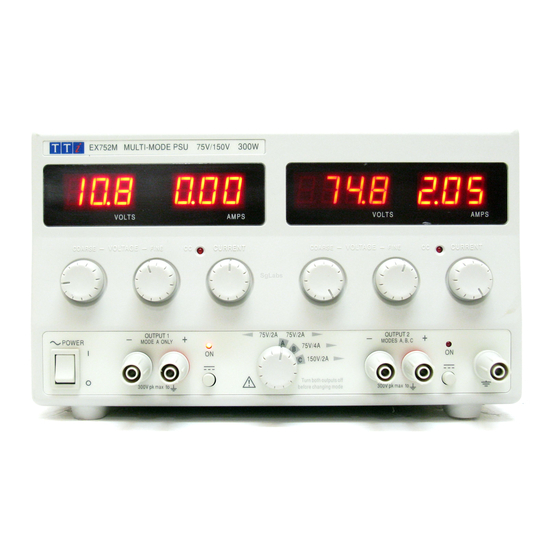
- Page 2 Table of Contents Specification Safety General Circuit Description Calibration Parts List Component Layouts Circuit Diagrams Specification OUTPUTS Voltage Range: 0V to 75V minimum, Modes A and B. 0V to 150V minimum, Mode C. Current Range: 0A to 2A minimum, Modes A and C. 0A to 4A minimum, Mode B.
- Page 3 OPERATING MODES Mode Selection: By front panel rotary switch. Mode A: Independent outputs each capable of 0-75V at 0-2A. Mode B: Output 2 only active, 0-75V at 0-4A. Output 1 disabled. Mode C: Output 2 only active, 0-150V at 0-2A. Output 1 disabled.
- Page 4 Safety This power supply is a Safety Class I instrument according to IEC classification and has been designed to meet the requirements of EN61010-1 (Safety Requirements for Electrical Equipment for Measurement, Control and Laboratory Use). It is an Installation Category II instrument intended for operation from a normal single phase supply.
- Page 5 General Service Handling Precautions Service work or calibration should only be carried out by skilled engineers using high quality test equipment. If the user is in any doubt as to his competence to carry out the work, the instrument should be returned to the manufacturer or their agent overseas for the work to be carried out. The tracks on the printed circuit boards are very fine and may lift if subjected to excessive heat.
- Page 6 Circuit Description Main Pcb Mains Input, Filtering and Rectification The AC input is via a pcb mounted IEC plug, PJ3. X-capacitors C1, C9 and C47, together with the Y-capacitors C6, C7 and common mode inductors L1 and L2 comprise an input filter which ensures that the supply meets both conducted emission and conducted immunity EMC requirements.
- Page 7 Boost Stage and Forward Converter Q5 and boost inductor L3 raise the incoming, full wave rectified, sinusoidal mains voltage to a value some 20V higher than the peak of the maximum rms input voltage. This is achieved by storing energy in L3 when Q5 is conducting and transferring it to C88 via boost diode D54 when Q5 is turned off.
- Page 8 Again referring to channel A, the +15V is peak rectified by D40 and zener regulated by D42. The +5V rail is rectified by D18, D19 and filtered by L4 and C23. The inductor L4 is held in continuous conduction and thus the voltage at the input to the three terminal regulator IC2 is maintained at low value.
- Page 9 Measurement and Display The measurement and display is controlled by a microcontroller, IC3. IC5, IC2 and associated components, together with IC3, form a dual slope A-to-D converter. Multiplexer IC4, under the control of IC3, selects the signals to be measured. The status line SW1 from the output ON/OFF switch is read by IC3 to determine which signals are measured, as follows: Status Voltage Measurement...
- Page 10 Calibration Refer to the General section for dismantling instructions and safety precautions. Component adjustment references are given as Channel A/ Channel B, e.g. VR5/VR105; Channel A is the left-hand output. All adjustments are on the front panel control board unless otherwise stated. Allow 5 minute warm-up before commencing calibration.
- Page 11 Voltage Regulation Connect the DMM (set to Volts) across the output, no load, output ON. Adjust voltage controls for a reading of 18.xxxx on the DMM; note exact reading. Connect load and adjust it to give an output current of 2.00A on the Amps display. Adjust VR9/109 (differential voltage gain) until the external DMM matches the previous reading.
- Page 12 Parts List PCB ASSY – MAIN (44115-0960) Part Number Description Position 20030-0263 WASHER M3 ZPST SPACERS, BR1 20037-0301 WASHER M3 SHK/PROOF I/T ZPST SPACERS TO UNDERSIDE OF PCB 20038-9501 WASHER M3 Spring SPACERS, BR1 20210-0101 NUT M3 ZPST 20234-0011 SCREW M3 X 10 PNHDPZ ZPST 20234-0027 SCREW M3 X 6 PNHDPZ ZPST SPACERS...
- Page 13 PCB ASSY – MAIN (44115-0960) continued/... Part Number Description Position 23202-0220 RES 22R0F W25 MF 50PPM R13,67,68,69,70,105,120,121 23202-0330 RES 33R0F W25 MF 50PPM R127 23202-0470 RES 47R0F W25 MF 50PPM R11,15,122 23202-1100 RES 100RF W25 MF 50PPM R44,106 23202-1220 RES 220RF W25 MF 50PPM 23202-1330 RES 330RF W25 MF 50PPM 23202-1470...
- Page 14 PCB ASSY – MAIN (44115-0960) continued/... Part Number Description Position 23222-0047 RES 4R70J W33 MF FUSIBLE NFR25 R7,21,22,23,24,54 23222-0220 RES 22R0J W33 MF FUSIBLE NRF25 R17,110,111 23222-1100 RES 100RJ W33 MF FUSIBLE NRF25 R37,38 23222-1220 RES 220RJ W33 MF FUSIBLE NFR25 R99,100,102,103 23222-1470 RES 470RJ W33 MF FUSIBLE NFR25...
- Page 15 PCB ASSY – MAIN (44115-0960) continued/... Part Number Description Position 23620-9007 CAP 10NK 100V P/E P5 C90,91,101 23621-0314 CAP 1UOK 400V P/E P27.5 23684-0016 CAP 220NM 250VAC MIN X2 P22.5 23684-0020 CAP 1UM 250VAC X2 P/P P27.5 C1,9,47 23685-0013 CAP 330NK 160V P/P P15 C16,94,119 25021-0901 DIO 1N4148 B/R...
- Page 16 PCB ASSY – MAIN (44115-0960) continued/... Part Number Description Position 27001-0060 OPTO-COUPLER SFH615A-3 IC12-16 27160-0009 IC V/REG 7805 IC2,3 27160-0013 IC V/REG 7815 27168-0040 IC L4981A 27226-0130 IC 4013B 27226-0690 IC 4069UB 27226-0930 IC 4093B 35515-1620 PCB - MAIN PCB ASSY - CONTROL (44115-0970) Part Number Description Position...
- Page 17 PCB ASSY - CONTROL (44115-0970) continued/... Part Number Description Position 23202-3866 RES 86K6F W25 MF 50PPM R156 23202-4100 RES 100KF W25 MF 50PPM R3,59,61,159 23202-4180 RES 180KF W25 MF 50PPM 23202-4210 RES 210KF W25 MF 50PPM 23202-4220 RES 220KF W25 MF 50PPM R36,37,42,136,137,142 23202-4270 RES 270KF W25 MF 50PPM...
- Page 18 PCB ASSY - CONTROL (44115-0970) continued/... Part Number Description Position 23685-0007 CAP 100NK 160V P/P MKP4 P10 C2,102 25021-0901 DIO 1N4148 B/R D1,2,3,4,5,7,8,9,11,12,13,101,102,103,104, 105,107,108,109,113 25061-0200 LED - T1 ROUND (3mm) - RED LED1,2,101,102 25061-0519 DISPLAY 3 DIG .56 LED 9MM LEG DIS1,2,102 25061-0520 DISPLAY 4 DIG .56 LED 9MM LEG...
- Page 19 33533-0370 OVERLAY DISPLAY WINDOW 33533-0400 OVERLAY DISPL WINDOW 33536-4090 CHASSIS 33536-4220 COVER 37151-0470 KNOB 21MM SPLINE L/GREY F/R 37151-0331 KNOB - MACHINED - 21MM SPLINED 44115-0960 PCB ASSY - MAIN 44115-0970 PCB ASSY - CONTROL 48511-0350 INSTRUCTION BOOK - EX752M...
- Page 20 Component Layouts Main Board...
- Page 21 Control Board...
- Page 22 Circuit Diagrams...
- Page 26 Thurlby Thandar Instruments Ltd Glebe Road, Huntingdon, Cambridgeshire PE29 7DR, England Telephone: (44) 01480 412451 Fax: (44) 01480 450409 e mail: sales@tti-test.com web site: www.tti-test.com...
Need help?
Do you have a question about the EX752M and is the answer not in the manual?
Questions and answers