
Related Manuals for HobbyZone HBZ7600 Glasair Sportsman


Summary of Contents for HobbyZone HBZ7600 Glasair Sportsman
- Page 1 ® ® Instruction Manual • Bedienungsanleitung • Manuel d’utilisation • Manuale di Istruzioni Designed in cooperation with and licensed by Glasair Aviation. ®...
- Page 2 NOTICE NOTICE All instructions, warranties and other collateral documents are subject to change at the sole discretion of Horizon Hobby, Inc. For up-to-date product literature, visit www.horizonhobby.com and click on the support tab for this product. Meaning of Special Language: Meaning of Special Language: The following terms are used throughout the product literature to indicate various levels of potential harm when operating this product: NOTICE: Procedures, which if not properly followed, create a possibility of physical property damage AND little or no possibility of injury.
-
Page 3: Table Of Contents
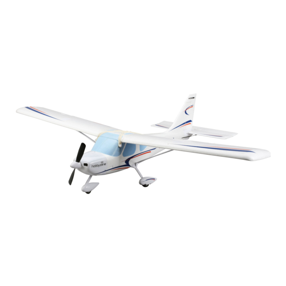
Introduction Your HobbyZone ® Glasair ® Sportsman ® aircraft is an innovative RC airplane designed to be the most advanced 4-channel trainer ever offered. Even if you’ve ™ never been at the controls of a quality hobby-grade aircraft like this one, the state-of-the-art electronic assistance of patent pending Virtual Instructor technology will help you quickly master the controls and have fun. -
Page 4: Charging The Flight Battery
Charging the Flight Battery Your aircraft comes with a DC Flight Battery charger that is specifi cally designed to charge the included 3S Li-Po battery. 1. Insert the charger into the car outlet. 2. Connect the battery to the charger. 3. -
Page 5: Understanding The Controls Of The Transmitter
Transmitter continued Understanding the Controls of the Transmitter * The diagram shows the For more information on the transmitter, go transmitter controls for Mode 2 to www.horizonhobby.com/products/ Antenna and Mode 1 transmitters. SPMR4400 and click on the support tab for the Spektrum DX4e to download the Handle Mode 2 Mode 1... -
Page 6: Installing The Main Landing Gear
Installing the Main Landing Gear The nose gear is installed at the factory. Always ensure the steering linkage clevis on the rudder servo arm is correctly adjusted so the nose steers straight when the rudder control is at neutral. 1. Turn the model so you can see the bottom of the fuselage. -
Page 7: Installing The Wing
Installing the Wing 1. Connect the left and right struts (A) (marked L and R) to the respective sides of the wing (B) using the included screws (C). Leave the screws loose until the wing is installed on the fuselage and the ball ends are snapped into place. -
Page 8: Installing The Flight Battery And Arming The Electronic Speed Control (Esc)
Installing the Flight Battery and Arming the Electronic Speed Control (ESC) 1. Rest the aircraft on a fl at surface with the landing gear facing up. 2. Turn the latch (A) and remove the battery hatch. 3. Lower the throttle and throttle trim, then power on the transmitter for at least 5 seconds. -
Page 9: Verifying Your Aircraft's Center Of Gravity (Cg)
Verifying Your Aircraft’s Center of Gravity (CG) An aircraft with correct CG has its weight balanced on the center of the aircraft for safe, stable fl ight. Verify the CG by supporting the aircraft 45mm (approxi- mately 1.75 inches) back from the front edge of the wing, as shown. -
Page 10: Control Direction Test
Control Direction Test IMPORTANT: Perform the Control Direction Test before Transmitter command Control Surface Reaction activating Virtual Instructor (advancing the throttle above 25% for the fi rst time). Mode 1 Mode 2 1. Power on the transmitter. Up Elevator 2. Make sure the throttle is at 0% and the throttle trim is Command fully lowered on the transmitter. -
Page 11: Flight Control
Flight Control For smooth control of your aircraft, always make Transmitter command Aircraft Reaction small corrections. All directions are described as if you were sitting in the aircraft. Mode 1 Mode 2 When the aircraft’s nose is pointing toward you, left aileron will bank and turn the aircraft left (your right while holding the transmitter). -
Page 12: Flight Trimming
Flight Trimming Move the trim sliders for the controls as they are as- Aircraft drift Required Trim signed on your transmitter. Familiarize yourself with your transmitter’s controls and the aircraft’s response before fl ying by performing the recommended Control Direction Test. If you must use more than 4 clicks on a trim slider to Up Trim make the aircraft fl... -
Page 13: Choose A Flying Field
Choose a Flying Field In order to have the most success and to protect your property and aircraft, it is very important to select a place to fl y that is very open. Consult local laws and ordinances before choosing a location to fl y your aircraft. The site should: •... -
Page 14: Virtual Instructor Training Steps
™ Virtual Instructor Technology Aileron to rudder and elevator mixing - Assists with stability in The patent pending Virtual Instructor (VI) system will not activate until turns. Active only when VI is in Training Step 1 or 2. the throttle stick or trim is increased for the fi rst time. Once VI is ac- tive, the control surfaces may move rapidly and noisily on the aircraft. -
Page 15: Flying Tips
Flying Tips A good fl ying day is calm, with winds that are less than • Resist the desire to fl y at full throttle. Flying slowly at fi rst allows for greater 5–7 mph (8–11km/h). Flying in faster winds than this response time should anything go wrong. - Page 16 Flying 1. Let the aircraft climb at full throttle, into the wind, until the aircraft gets about 300 feet (91meters) above the ground, then decrease the throttle to half (50%). Tip: When properly trimmed, your aircraft’s wing design causes a climb at full throttle without use of elevator. 50% throttle Try to make only small and gentle movements of the control sticks so you can see how the aircraft responds.
-
Page 17: Transmitter And Receiver Binding
Transmitter and Receiver Binding The aircraft should be bound to the transmitter at the fac- Binding Procedure Reference Table tory, but if you need to re-bind them, follow these steps. If your aircraft does not respond to the transmitter when the Make sure the transmitter is powered off. -
Page 18: Service Of Power Components
Service of Power Components CAUTION: Always disconnect the fl ight battery from the model before removing the propeller. Disassembly 1. Remove the screw (A) and the spinner (B) from the hex nut (C). 2. Remove the hex nut, propeller (D) and plate (E) from the collet (F). -
Page 19: Trouble Shooting Guide
Trouble Shooting Guide Problem Possible Cause Solution Unit does not operate There is no link between the transmitter and receiver Re-Bind the system following directions in this manual Transmitter AA batteries are depleted or installed Check polarity installation or replace with fresh AA batteries incorrectly as indicated by a dim or unlit LED on the transmitter or the low battery alarm No electrical connection... -
Page 20: Ama National Model Aircraft Safety Code
AMA National Model aircraft Safety Code Effective January 1, 2011 B. RADIO CONTROL A. GENERAL 1. All pilots shall avoid fl ying directly over unprotected people, vessels, A model aircraft is a non-human-carrying aircraft capable of sustained vehicles or structures and shall avoid endangerment of life and prop- fl... -
Page 21: Limited Warranty
Limited Warranty What this Warranty Covers Inspection or Services Horizon Hobby, Inc. (“Horizon”) warrants to the original purchaser that the If this Product needs to be inspected or serviced and is compliant in the product purchased (the “Product”) will be free from defects in materials country you live and use the Product in, please use the Horizon Online and workmanship at the date of purchase. -
Page 22: Contact Information
Contact Information Country of Purchase Horizon Hobby Address Phone Number/Email Address 4105 Fieldstone Rd 877-504-0233 Horizon Service Center Champaign, Illinois Online Repair Request: (Electronics and engines) 61822 USA visit www.horizonhobby.com/service United States of 4105 Fieldstone Rd America Horizon Product Support 877-504-0233 Champaign, Illinois (All other products) -
Page 23: Parts Contact Information
Landing Gear Set: Glasair Hobbyzone Glasair : Spinner Cône : Glasair Ogiva: Glasair HBZ7618 Prop Adapter: Glasair Hobbyzone Glasair : Propeller Adapter Adaptateur d’hélice : Glasair Adattatore elica: Glasair PKZ1019 9x6 Propeller Parkzone P-51 Luftschraube BL 9x6 Hélice 9x6 Elica 9x6... - Page 24 © 2012 Horizon Hobby, Inc. HobbyZone, Virtual Instructor, Bind-N-Fly, Z-Foam, DSM, DSM2, DSMX, EC3 and the Horizon Hobby logo are trademarks or registered trademarks of Horizon Hobby, Inc. The Spektrum trademark is used with permission of Bachmann Industries, Inc. Glasair, Sportsman, the Glasair logo and the aircraft body designs are trademarks or registered trademarks of Glasair Aviation USA, LLC and are used with permission by Horizon Hobby, Inc.
Need help?
Do you have a question about the HBZ7600 Glasair Sportsman and is the answer not in the manual?
Questions and answers