Motorola VC6000 Series Product Reference Manual
Vehicle computers
Hide thumbs
Also See for VC6000 Series:
- Quick reference manual (33 pages) ,
- Quick reference manual (41 pages)
Table of Contents
Advertisement
Quick Links
Advertisement
Table of Contents

Related Manuals for Motorola VC6000 Series


Summary of Contents for Motorola VC6000 Series
- Page 1 VC6000 Series Vehicle Computers Product Reference Guide...
- Page 3 VC6000 Series Product Reference Guide 6802986C08 Rev. A December 2008...
- Page 4 Motorola. No right to copy a licensed program in whole or in part is granted, except as permitted under copyright law. The user shall not modify, merge, or incorporate any form or portion of a licensed program with other program material, create a derivative work from a licensed program, or use a licensed program in a network without written permission from Motorola.
- Page 5 Revision History Changes to the original manual are listed below: Change Date Description -01 Rev A 11/30/2008 Initial release...
- Page 6 VC6000 Series Product Reference Guide...
- Page 7 Getting Started ............................. 1-7 Installing a SIM Card ........................1-7 Installing an SD Memory Card ....................... 1-8 Installing the VC6000 Series ......................1-8 Starting with the VC6000 Series ....................1-9 Standby Mode .......................... 1-9 Resume from Standby Mode ....................1-9...
-
Page 8: Table Of Contents
Clean Boot ..........................1-10 Function Keys ..........................1-10 Chapter 2: Installation Introduction ............................2-1 Installing the VC6000 Series in a Vehicle .................... 2-2 Guidelines for Routing Cables ....................... 2-2 Connecting the Vehicle Power Cable .................... 2-3 Cigarette Lighter Cable ........................2-3 Telemetry Cables ........................... - Page 9 Table of Contents Using a Bluetooth Headset ......................4-3 Adjusting Audio Volume ......................... 4-3 Making a Call ............................4-4 Using the Phone ..........................4-4 Using Contacts ..........................4-4 Using Call History .......................... 4-4 Making a Speed Dial Call ....................... 4-5 Making an Emergency Call ........................
- Page 10 Virtual COM Port Tab ........................6-31 HID Tab ............................6-32 Profiles Tab ............................ 6-32 System Parameters Tab ........................ 6-33 Miscellaneous Tab ......................... 6-33 Chapter 7: GSM Configuration Introduction ............................7-35 Quick Startup Steps ..........................7-35 VC6000 Series Service Verification ..................... 7-36...
- Page 11 Service Provider Name Display ......................7-49 Chapter 8: Using GPS Navigation Introduction ............................8-1 Software Installation ..........................8-1 VC6000 Series GPS Setup ........................8-1 Operation ............................. 8-2 GPS Maps on microSD Cards ....................... 8-2 Answering a Phone Call While Using GPS ..................8-2 Losing the GPS Signal While in a Vehicle ..................
- Page 12 VC6000 Series Product Reference Guide Display ............................. 10-2 Connectors ..........................10-2 Cleaning Frequency ........................10-3 Troubleshooting ........................... 10-4 VC6000 Series ..........................10-4 Bluetooth Connection ........................10-6 Appendix A: Specifications VC6096/VC6000 Specifications ......................A-1 Index Glossary...
-
Page 13: About This Guide
NOTE Screens and windows pictured in this guide are samples and can differ from actual screens. Documentation Set The documentation set for the VC6000 Series is divided into guides provide information for specific user needs. • VC6000 Quick Reference Guide - describes how to start using the VC6000 Series. - Page 14 VC6000 Series Product Reference Guide Software Versions This guide covers various software configurations and references are made to operating system or software versions for: • OEM version • Hardware version. OEM Software To determine the OEM software version: Tap Start > Settings > System info icon > System tab.
- Page 15 Chapter Descriptions Topics covered in this guide are as follows: • Chapter 1, Getting Started, provides information on getting the VC6000 Series up and running for the first time. • Chapter 2, Installation, provides instructions for installing the VC6000 Series in a vehicle or on a desktop.
- Page 16 For the latest version of this guide and all guides, go to: www.motorola.com/enterprisemobility/manuals. Service Information If you have a problem with your equipment, contact Motorola Enterprise Mobility Support for your region. Contact information is available at: www.motorola.com/enterprisemobility/support. When contacting Enterprise Mobility Support, please have the following information available:...
- Page 17 Software type and version number. Motorola responds to calls by E-mail, telephone or fax within the time limits set forth in support agreements. If your problem cannot be solved by Motorola Enterprise Mobility Support, you may need to return your equipment for servicing and will be given specific directions.
- Page 18 VC6000 Series Product Reference Guide...
-
Page 19: Introduction
Unpacking the VC6000 Series When you remove the VC6000 Series from its box, save the box and shipping material in case you need to ship or store it. Check the contents of the box against the invoice for completeness and contact your local Motorola service representative if there is a problem. -
Page 20: Optional Accessories
Service Information on page xiv for contact information. NOTE A hardware kit that contains optional accessories is provided separately inside the shipping box. Optional Accessories Table 1-1 describes the optional accessories of the VC6000 Series. Optional Accessories Table 1-1 Part Number Description FLN4048... -
Page 21: Model Configurations
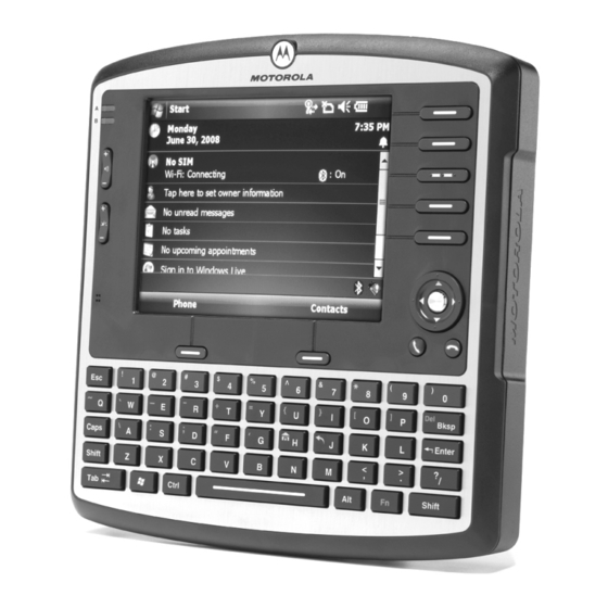
Yes (802.11a/b/g) Cellular Radio Yes (Voice and data) (HSDPA, UMTS, GSM, GPRS, EDGE) Vehicle Telemetry Features The VC6000 Series has the following features: • Ergonomic design with a color LCD touch screen • Windows Mobile 6.1 operating system • Internal Bluetooth radio to enable wireless connection to a Bluetooth printer, bar code scanner, headset and other Bluetooth peripherals •... - Page 22 1 - 4 VC6000 Series Product Reference Guide Power Button with System Indication LED Application LEDs - two Green LEDs Driven by Application Touch Screen Volume up/down Key Function Keys Brightness up/down Key Speaker (embedded) Microphone (embedded) Select Key Navigation Key...
- Page 23 Getting Started 1 - 5 USB Port, Type A M4 Screw Mounting Bosses Mini USB Port, Type B M4 Ground Screw Boss USB Port, Type A Power Connector Cable Retention Bracket SD Memory Card Slot SIM Card Slot (used in VC6096 only) GPS Antenna Connector (used in VC6096 only) Auxiliary Port...
-
Page 24: System Indication Led
The VC6000 Series may turn off. Application LEDs The Application LEDs are located on the upper left hand side of the VC6000 Series front panel. To know more about the function of Application LEDs, refer to the operating manual provided by your organization. -
Page 25: Getting Started
Torque the T8 screw to 3.4 kgf-cm (3 in-lbs). SIM Slot SIM Card T8 Screw SIM Card Door SIM Card Installation Figure 1-3 CAUTION Ensure to torque the screw to seal the VC6000 Series properly. Otherwise, sealing can be compromised. -
Page 26: Installing An Sd Memory Card
Lift up the Protective Rubber Cap that covers the Memory Card Slot. Position the SD memory card with the contacts facing the back of the VC6000 Series and insert into the Memory Card Slot. The corner notch of the SD memory card fits into the Memory Card slot only one way. -
Page 27: Starting With The Vc6000 Series
Starting with the VC6000 Series The VC6000 Series is automatically powered on when connected to the vehicle. The VC6000 Series turns to Standby mode when the vehicle is turned off. In Standby mode, the screen automatically turns off after some time. -
Page 28: Resetting The Vc6000 Series
VC6000 during a clean boot may render the VC6000 inoperable. Clean boot may become necessary when your VC6000 Series is jammed and does not respond to cold boot. A clean boot resets the VC6000 Series to the factory default settings. All applications installed by your organization are erased and should be re-installed on the VC6000 Series. - Page 29 Chapter 2 Installation Introduction This chapter describes how to install the VC6000 Series in a vehicle or on a desktop and connecting the VC6000 Series to a power source. This chapter also describes how to install the various accessories for the VC6000 Series.
-
Page 30: Guidelines For Routing Cables
VC6000 Series. • If you must re-position the VC6000 Series occasionally, ensure there is enough slack in the cable to accommodate movement without putting tension on the cable. •... -
Page 31: Connecting The Vehicle Power Cable
Installation 2 - 3 Connecting the Vehicle Power Cable CAUTION DO NOT install the VC6000 Series in a vehicle with a positive ground electrical system. To connect the power cable (see Figure 2-2): Disconnect the power terminals from the vehicle battery. -
Page 32: Telemetry Cables
Vehicle telemetry information is also used for maintenance and diagnose of the vehicle condition The VC6000 Series is equipped with a built in (on–board) capability to interface with Heavy-Duty type bus (SAE J1708, J1939) without an external adapter. Vehicle bus type can be selected manually or automatically via API. - Page 33 Installation 2 - 5 9 Pin Deutsch Cable Connect J1 connector into the Auxiliary port of the VC6000 Series (see Figure 2-4). Fasten the connector’s screws. Connect J2 - J3 plugs to the telemetry receptacles of your vehicle data bus.
- Page 34 NOTE The 6 Pin Deutsch Telemetry Cable only supports heavy-duty vehicle bus type SAE J1708. The 6 Pin Deutsch Telemetry Cable supports protocol 1708 interface with Heavy-Duty type bus (SAE J1708) Connect J1 serial connector into the Auxiliary port of the VC6000 Series (see Figure 2-6).
- Page 35 The 50 Pin Accessory Cable serves as an adaptor cable betwwen the 9 Pin Deutsch Telemetry Cable (P.N 3089906Y63) or 6 Pin Deutsch Telemetry Cable (P.N 3089906Y63) and the VC6000 Series. Connect the cable into the Auxiliary port of the VC6000 Series (see Figure 2-8).
- Page 36 2 - 8 VC6000 Series Product Reference Guide Auxiliary Connector Pinout Details (Continued) Table 2-2 Pin # Name Functionality General purpose digital input port (switch detect, 5,12 or 24V inputs). Negative sense to either vehicle Ground or battery negative terminal.
- Page 37 J1939 telemetry communication port (negative terminal) CAN_Shield CAN Shield (RC to GND) To program the operation of input/output, refer to Enterprise Mobility Developer Kits (EMDKs). To program minimum and maximum thresholds for port notification, refer to the VC6000 Series Software Developer Kit for C (SDK).
-
Page 38: Mounting The Combination Antenna (Vc6096 Only)
2 - 10 VC6000 Series Product Reference Guide Mounting the Combination Antenna (VC6096 only) The Combination Antenna is an optional omni-directional WWAN and WLAN antenna used with the VC6096. The antenna mounts inside/outside the vehicle cabin or indoors/outdoors (see Figure 2-10). - Page 39 Installation 2 - 11 Combination antenna installation guidelines (see Figure 2-10): For best performance, it is recommended to install the antenna outside of the cabin. When installing the antenna in the vehicle cabin or indoors, keep a minimum distance of 70 cm (2.3 ft.) between the antenna and the VC6096.
-
Page 40: Installing The Gps Antenna
Connect the cable connector of the GPS antenna to the GPS connector at the back of the VC6096 (see Figure 1-2 on page 1-5). CAUTION To avoid damage to the VC6000 Series, disconnect the power cable from the VC6000 Series before connecting the antenna cable. GPS antenna Installation guidelines (see Figure 2-11): Recommended GPS antenna - Motorola part number 8508851K59. -
Page 41: Using The Vc6000 Series Indoor
Installation 2 - 13 Using the VC6000 Series Indoor When using the VC6000 Series indoor, the VC6000 Series can be placed on a desk and powered using an Indoor Power Supply Unit. To connect the VC6000 Series indoor (see Figure 2-12): Connect a ground wire between the VC6000 Series and the facility ground system. -
Page 42: Optional Mounting
A single adjustment knob enables simultaneous adjustment of both upper and lower ball joints. The mount affixes to the VC6000 Series using the M4 screws, included inside the hardware kit, and to the vehicle’s dashboard using self tapping screws or bolts, provided by the mount manufacturer. -
Page 43: Mounting Bracket Template For The Vc6000 Series
The Desk Mount (see Figure 2-14) allows the VC6000 Series to be easily placed on a desk and adjusted to a most comfortable screen view position. A single adjustment knob enables adjustment of both upper and lower ball joints simultaneously. The mount affixes to the VC6000 Series using the M4 screws, included inside the hardware kit. - Page 44 All nuts and bolts must be checked periodically and tightened if required. • When installing the VC6000 Series, care must be taken to ensure that the mounting bracket footprint is fully supported. Additional plates may be required to achieve this.
- Page 45 Chapter 3 Getting Started Series Introduction This chapter explains the keyboard, buttons, status icons and controls on the VC6000 Series, and provides basic instructions for using the VC6000 Series, including powering on and resetting the VC6000 Series, and entering and capturing data.
-
Page 46: Using The Keyboard
3 - 2 VC6000 Series Product Reference Guide Using the Keyboard QWERTY of the VC6000 or VC6096 can be used with the full-screen VC6000 Series. For keyboard functionality, Refer to Figure 3-1 Figure 3-1 for a description of the keys. -
Page 47: Keyboard Functionality
To program the operation of Function keys, refer to Enterprise Mobility Developer Kits (EMDKs). Soft Keyboard The VC6000 Series contains two on-screen Soft Input Panel (SIP) keyboards (see Figure 3-2). The Microsoft SIP looks and functions like a standard keyboard. The VC6000 Series SIP looks and functions like the optional keyboard. - Page 48 3 - 4 VC6000 Series Product Reference Guide To display the Microsoft SIP keyboard, tap the Input Panel icon in the task tray and select Keyboard from the pop-up menu. Soft Input Panel (SIP) Input Panel icon Soft Input Panel Keyboard...
-
Page 49: Starting The Mobile Computer Boot Up
The VC6000 Series starts automatically as soon as power is applied; either with a connection to the vehicle power system or when connected to the Indoor Power Supply Unit. If the VC6000 Series does not power on, perform a cold boot. -
Page 50: Status Icons
3 - 6 VC6000 Series Product Reference Guide To customize the Today screen, tap Start > Settings > Today icon. Use the Appearance tab to customize the background and the Items tab to change the list and order of items that appear on the screen. - Page 51 Getting Started 3 - 7 Status Icons (Continued) Table 3-2 Icon Function Description Speaker All sounds are on. All sounds are off. Time and Next Displays current time in analog or digital format. Appointment...
- Page 52 Bluetooth radio is off. Bluetooth Connection Bluetooth radio is connected to another Bluetooth device. ActiveSync Active serial connection between the VC6000 Series and the host computer. Programs Table 3-4 lists the default programs on the Start menu. Programs in the Start Menu...
- Page 53 Programs in Program Window Table 3-5 Icon Name Description ActiveSync Synchronize information between the VC6000 Series and a host computer or the Exchange Server. AirBEAM Allows specially designed software packages to be transferred between a host server and the VC6000 Series. BTExplorer Manages Bluetooth connections.
- Page 54 Windows Media Player Play back audio and video files. Mobile Settings Table 3-6 lists control applications pre installed on the VC6000 Series. Tap Start > Settings to open the Settings Settings in the Setting Window Table 3-6 Icon Name Description...
- Page 55 Backlight Set the display backlight time-out and adjust brightness. Certificates See information about certificates installed on the VC6000 Series. Clock & Alarms Set the device clock to the date and time of your locale or to a visiting time zone when you’re traveling. Alarms can also be set at specified days and times of a week.
- Page 56 Displays the VC6000 Series’s software and hardware information. Windows Update Link to Microsoft's web site and update Windows Mobile® on your VC6000 Series with the latest security patches or fixes. Do not use. Obtain updates from Motorola. Connections Tab Beam Set the to receive incoming IrDA beams (not aplicable for the VC6000 Series).
- Page 57 Wi-Fi Setup wireless network connection and customize settings (VC6096 only). Wireless Manager Enables or disables the VC6000 Series wireless radios and customizes Wi-Fi, Bluetooth and Phone settings. The VC6000 Series factory default radio states are: Wi-Fi - ON. Bluetooth - OFF.
-
Page 58: Adjusting Volume
Select the On or Off radio button to turn the volume on or off. You can also adjust the system volume using the Sounds & Notifications window, or use the Up/Down button on the left hand side of the VC6000 Series front panel. -
Page 59: Accessing The Phone Keypad
Chapter 4 Using the Phone Introduction Use the VC6000 Series to make phone calls, set up speed dials, keep track of calls, and send text messages. Your wireless service provider may also provide other services such as voice mail, call forwarding, and caller ID. -
Page 60: Turning The Phone On And Off
4 - 2 VC6000 Series Product Reference Guide The VC6000 Series receive calls when the is in Suspend mode, leave the phone radio turned on. Turning the Phone On and Off Windows Mobile 6.1 devices include Wireless Manager, which provides a simple method of enabling and disabling the phone. -
Page 61: Using A Bluetooth Headset
NOTE Ensure that the Bluetooth headset is set to stay on. When using a Bluetooth headset, during a call the VC6000 Series power button is disabled and the VC6000 Series will not go into suspend mode. Once the call is completed, the power button functionality is enabled. -
Page 62: Making A Call
4 - 4 VC6000 Series Product Reference Guide Making a Call NOTE You can make emergency calls even when the VC6000 Series is locked or when a SIM card is not installed. Making an Emergency Call on page 4-5 for more information. -
Page 63: Making A Speed Dial Call
Tap the phone icon next to the number to begin dialing and return to the phone keypad. Tap End or press the red phone key on the VC6000 Series keypad to stop dialing or end the call. Making a Speed Dial Call Use Speed Dial to call someone saved in the speed dial directory. -
Page 64: Answering A Call
Answering a Call A dialog box appears on the VC6000 Series when it receives an incoming call. If the phone is set to ring, a ring tone sounds. Answer or ignore the incoming call. To answer an incoming call tap Answer on the Phone > Incoming... dialog or press the green phone key on the VC6000 Series keypad. -
Page 65: Smart Dialing
Using the Phone 4 - 7 Smart Dialing Smart Dialing makes it easy to dial a phone number. When you start entering numbers or characters, Smart Dialing automatically searches and sorts the contact entries on the SIM card, in Contacts, and the phone numbers in Call History (including incoming, outgoing, and missed calls). -
Page 66: Muting A Call
This is useful when there is conversation or background noise on your end. To mute or unmute a call: Tap Start > Phone or press the green phone key on the VC6000 Series’s keypad. Make a call. -
Page 67: Using Speed Dial
To add a speed dial entry from the phone keypad: Ensure the contact and phone number are in the Contacts list. Tap Start > Phone or press the green phone key on the VC6000 Series’s keypad. Tap Start > Speed Dial > Menu > New. -
Page 68: Editing A Speed Dial Entry
Tap the up/down arrows to select an available location to assign as the new speed dial entry. The first speed dial location is reserved for voice mail. Tap ok. Editing a Speed Dial Entry Tap Start > Phone or press the green phone key on the VC6000 Series’s keypad. -
Page 69: Deleting A Speed Dial Entry
Contacts > Deleting a Speed Dial Entry Tap Start > Phone or press the green phone key on the VC6000 Series’s keypad. Tap Menu > Speed Dial. Tap and hold the contact name. Speed Dial Delete Menu Figure 4-18 Tap Delete. -
Page 70: Using Call History
Change views, reset the call timer, and delete calls to manage the calls stored in Call History. Changing the Call History View Tap Start > Phone or press the green phone key on the VC6000 Series’s keypad to display the Phone keypad. From the Phone keypad, tap Call History. -
Page 71: Deleting Call History Items By Call Date
Tap ok to exit the Call Timers window. Deleting Call History Items by Call Date Tap Start > Phone or press the green phone key on the VC6000 Series’s keypad to display the Phone keypad. From the Phone keypad, tap Call History. -
Page 72: Viewing Call Status
Tap ok to exit the Call History window. Viewing Call Status Tap Start > Phone or press the green phone key on the VC6000 Series’s keypad to display the Phone keypad. From the Phone keypad, tap Call History. Tap an entry. The Call Status window appears. -
Page 73: Using The Call History Menu
Use the Call History menu to dial voice mail, access the Activation Wizard, save to contacts, view a note, delete a listing, send an SMS, and make a call. Tap Start > Phone or press the green phone key on the VC6000 Series’s keypad to display the Phone keypad. From the Phone keypad, tap Call History. -
Page 74: Conference Calling
To create a conference phone session with multiple people: Tap Start > Phone or press the green phone key on the VC6000 Series’s keypad to display the Phone keypad. Enter the first phone number and press Talk. When the call connects, Hold appears on the keypad. -
Page 75: Text Messaging
After the call is answered, tap Menu > Conference to place all the calls in conference mode. Repeat steps 6 through 8 for up to six phone numbers. Tap End or press the red phone key on the VC6000 Series keypad to end the conference call. Menu... - Page 76 4 - 18 VC6000 Series Product Reference Guide Text Message Notification Icon New Text Message Notification Figure 4-32 The Caller Identification feature matches incoming text message numbers with those stored in Contacts so you know who is sending you a message. Furthermore, the New Text Message dialog box gives you the option to call the sender or save, dismiss, or delete the message.
-
Page 77: Sending A Text Message
Using the Phone 4 - 19 Tap to reply the message. Text Messages List Figure 4-36 NOTE If the phone is turned off and you tried to call the sender, send a reply, or forward the message, you are prompted to turn the phone function on. Sending a Text Message To create a text message: On the Phone screen, select a contact name that you want to send a message to. - Page 78 If you are out of coverage area, the message is saved in the Drafts folder and sent when you return to a coverage area. NOTE On VC6000 Series, the message remains in the Drafts folder and has to be manually re-sent when you return to a coverage area.
-
Page 79: Chapter 5: Wireless Applications Introduction
Wireless Local Area Networks (LANs) allow mobile computers to communicate wirelessly and send captured data to a host device in real time. Before using the VC6000 Series on a WLAN, the facility must be set up with the required hardware to run the wireless LAN and the VC6000 Series must be configured. Refer to the documentation provided with the access points (APs) for instructions on setting up the hardware. -
Page 80: Signal Strength Icon
5 - 2 VC6000 Series Product Reference Guide Wireless Applications Menu Figure 5-1 Signal Strength Icon icon in the task tray indicates the VC6000 Series’s wireless signal strength as follows: Signal Strength Signal Strength Icon Table 5-1 Icon Status Action Excellent signal strength Wireless LAN network is ready to use. -
Page 81: Turning The Wlan Radio On And Off
Wireless Applications 5 - 3 Turning the WLAN Radio On and Off To turn the WLAN radio off tap the icon and select Signal Strength Disable Radio Disable Radio Figure 5-2 To turn the WLAN radio on tap the icon and select Signal Strength Enable Radio Enable Radio... - Page 82 5 - 4 VC6000 Series Product Reference Guide...
-
Page 83: Chapter 6: Using Bluetooth Introduction
Hop Sequence Modification - Avoids interference by selectively reducing the number of hopping channels. • Channel Maintenance - A method for periodically re-evaluating the channels. When AFH is enabled, the Bluetooth radio “hops around” (instead of through) the 802.11b high-rate channels. AFH coexistence allows Motorola mobile computers to operate in any infrastructure. -
Page 84: Security
VC6000 Series Product Reference Guide The Bluetooth radio in this VC6000 Series operates as a Class 2 device power class. The maximum output power is 2.5mW and the expected range is 32.8 feet (10 meters). A definition of ranges based on power class is difficult to obtain due to power and device differences, and whether one measures open space or closed office space. -
Page 85: Turning The Bluetooth Radio Mode On And Off
Turn off the Bluetooth radio to save power or if entering an area with radio restrictions (e.g., an airplane). When the radio is off, other Bluetooth devices cannot see or connect to the VC6000 Series. Turn on the Bluetooth radio to exchange information with other Bluetooth devices (within range). -
Page 86: Bluetooth Power States
Cold Boot Performing a cold boot on the VC6000 Series turns off Bluetooth after initialization (which takes a few moments). It is normal to see the Bluetooth icon appear and disappear, as well as a wait cursor, when initialization proceeds in all modes. - Page 87 Using Bluetooth 6 - 5 Explorer Mode Window Figure 6-3 You can also use the “tap and hold” technique to view available options. Scroll bars and view options are similar to those on the Windows desktop. The tree structure lists the following sub-items: •...
-
Page 88: Discovering Bluetooth Device(S)
Ensure that Bluetooth is enabled on both devices. Ensure that the Bluetooth device to discover is in discoverable and connectable modes. Ensure that the require profile is enabled on the VC6000 Series. See Profiles Tab on page 6-32 for more information. - Page 89 Using Bluetooth 6 - 7 The following actions are available in the drop-down list (actions may vary depending upon configurations): • Explore Services on Remote Device • Pair with a Remote Device • Active Sync via Bluetooth • Browse Files on Remote Device •...
- Page 90 6 - 8 VC6000 Series Product Reference Guide Select Remote Device Window Figure 6-6 Select a device from the list and tap Next. The VC6000 Series searches for services on the selected Bluetooth device. Device Services Figure 6-7 NOTE If the VC6000 Series discovers a service but the service is not supported, the service icon is grayed-out.
-
Page 91: Available Services
See the following sections for information on these services. File Transfer Services NOTE Shared folders are a security risk. To transfer files between the VC6000 Series and another Bluetooth enabled device: Ensure the VC6000 Series is discoverable and connectable. See Device Info Tab on page 6-23. - Page 92 6 - 10 VC6000 Series Product Reference Guide Ensure that OBEX File Transfer profile is enabled on the VC6000 Series. See Profiles Tab on page 6-32 for more information. NOTE If favorite connections have already been created, the Favorites screen displays. If no favorite connections have been created, the New Connection Wizard screen displays.
-
Page 93: Connecting To The Internet Using An Access Point
Internet Explorer to connect to a server. Ensure the VC6000 Series is discoverable and connectable. See Device Info Tab on page 6-23. Ensure that the Personal Area Networking profile is enabled on the VC6000 Series. See Profiles Tab on page 6-32 for more information. -
Page 94: Dial-Up Networking Services
NOTE Network Access profile is not supported. Dial-Up Networking Services Dial-up networking allows the user to connect a PC or laptop to the VC6000 Series and use the VC6000 Series as a modem to connect to an office network or ISP. -
Page 95: Object Exchange Push Services
To exchange contact information with another Bluetooth enabled device: Ensure the VC6000 Series is discoverable and connectable. See Device Info Tab on page 6-23. Ensure that the OBEX Object Push profile is enabled on the VC6000 Series. See Profiles Tab on page 6-32 for more information. - Page 96 6 - 14 VC6000 Series Product Reference Guide Select Contact Entry Window Figure 6-14 Select a contact to send to the other device. Tap OK. Tap OK to send the contact to the other device and display a confirmation dialog box on the other device to accept the contact.
- Page 97 Using Bluetooth 6 - 15 Select Contact Entry Window Figure 6-16 Select a contact to send to the other device. Tap OK. Tap OK to swap contacts with the other device and display a confirmation dialog box on the other device to accept the contact.
-
Page 98: Headset Services
6 - 16 VC6000 Series Product Reference Guide Tap and hold on OBEX Object Push and select Connect. The OBEX Object Push window appears. OBEX Object Push Window Figure 6-18 In the Action: drop-down list, select Send A Picture. . The Send Local Picture window appears. -
Page 99: Hands-Free Services
Hands-free profile does not support 3-way calling. Ensure the VC6000 Series is discoverable and connectable. See Device Info Tab on page 6-23. Ensure that the Hands Free profile is enabled on the VC6000 Series. See Profiles Tab on page 6-32 for more information. -
Page 100: Serial Port Services
To establish a serial port connection: Ensure the VC6000 Series is discoverable and connectable. See Device Info Tab on page 6-23. Use the Connection Wizard to search for a Bluetooth serial device. - Page 101 To establish an ActiveSync connection: Ensure the VC6000 Series is discoverable and connectable. See Device Info Tab on page 6-23. Ensure that the Sync profile is enabled on the VC6000 Series. See Profiles Tab on page 6-32 for more information.
-
Page 102: Personal Area Network Services
IrMC synchronization: Ensure the VC6000 Series is discoverable and connectable. See Device Info Tab on page 6-23. Ensure that the Sync profile is enabled on the VC6000 Series. See Profiles Tab on page 6-32 for more information. Tap Menu > Settings > Services tab. - Page 103 Using Bluetooth 6 - 21 To bond with a discovered Bluetooth device: NOTE If favorite connections have already been created, the Favorites screen displays. If no favorite connections have been created, the New Connection Wizard screen displays. Tap the Bluetooth icon and select Show BTExplorer. The BTExplorer window appears. Tap Menu >...
- Page 104 A confirmation dialog appears. Tap Yes. Accepting a Bond When a remote device wants to bond with the VC6000 Series, enter a PIN when requested to grant permission. Ensure that the VC6000 Series is set to discoverable and connectable. See Bluetooth Settings on page 6-23.
-
Page 105: Bluetooth Settings
Using Bluetooth 6 - 23 Tap OK to create the bond. The VC6000 Series can now exchange information with the other device. Bluetooth Settings Use the BTExplorer Settings window to configure the operation of the BTExplorer application. Tap Menu >... - Page 106 6 - 24 VC6000 Series Product Reference Guide To add a service: Tap Add. The Add Local Service window displays. Add Local Service Window Figure 6-29 In the list, select a service to add. Tap OK. The Edit Local Service window displays for the selected service.
- Page 107 Using Bluetooth 6 - 25 Local Service items Table 6-1 Item Description Local COM Port Select the COM port. Local Baud Rate Select the communication baud rate. Local Port Options Select the port option. File Transfer Service File transfer allows other Bluetooth devices to browse files. BTExplorer Settings - File Transfer Information Figure 6-31 File Transfer Information Data...
- Page 108 6 - 26 VC6000 Series Product Reference Guide Hands-Free Audio Gateway Service Hands-Free Service Audio Gateway allows connection to hands-free devices. BTExplorer Settings - Hands-Free Audio Gateway Figure 6-32 Hands-Free Audio Gateway Data Table 6-3 item Description Service Name Lists the name of the audio service.
- Page 109 Select the type of security from the drop-down list. Options are None, Authenticate, or Authenticate/Encrypt. Phonebook Select the Phonebook checkbox to allow synchronization with the VC6000 Series’s contacts. Select Read, Write, Create and/or Delete to allow phonebook permissions. OBEX Object Push Service OBEX Object Push allows other Bluetooth devices to push contacts, business cards, pictures, appointments, and tasks to the VC6000 Series.
- Page 110 Select the type of security from the drop-down list. Options are None, Authenticate, or Authenticate/Encrypt. Do not allow clients to push objects Disables clients from pushing objects to the VC6000 Series. Inbox Directory Select a directory where another Bluetooth device can store files.
-
Page 111: Security Tab
Using Bluetooth 6 - 29 Personal Area Networking Data Table 6-7 Item Description Service Name Displays the name of the service. Service Security Select the type of security from the drop-down list. Options are None, Authenticate, or Authenticate/Encrypt. Support Group Ad-Hoc Select to enable Ad-Hoc networking. -
Page 112: Discovery Tab
6 - 30 VC6000 Series Product Reference Guide BTExplorer Settings - Security Tab Figure 6-38 Authenticate Authenticate/Encrypt NOTE To use PIN Code, select from the Service Security drop-down list on each local service. Security Tab Data Table 6-9 Item Description Use PIN Code (Incoming Select for automatic use of the PIN code entered in the PIN Code text box. -
Page 113: Virtual Com Port Tab
Table 6-10 Item Description Inquiry Length Sets the amount of time the VC6000 Series takes to discover Bluetooth devices in the area. Name Discovery Mode Select either Automatic or Manual to automatically attempt to discover a Bluetooth device's name after finding the device. -
Page 114: Hid Tab
6 - 32 VC6000 Series Product Reference Guide HID Tab Use the HID tab to select The Human Interface Device Profile programming interface defines the protocols and procedures to be used to implement HID capabilities. Provides support for devices such as mice, joysticks, keyboards. -
Page 115: System Parameters Tab
Link Supervision Timeout Sets the amount of time that the VC6000 Series will wait for a device to come back into range after it has gone out of range. If the device does not come back into range by the set time, the VC6000 Series drops the connection. - Page 116 6 - 34 VC6000 Series Product Reference Guide Miscellaneous tab Data Table 6-14 Item Description Highlight Connections Select the connection type to highlight when connected. In the Wizard Mode, the only options are Favorites or None. In the Explorer Mode the options are None, Tree View Only, List View Only, or Tree and List View.
-
Page 117: Quick Startup Steps
ID, depending on the type of service. Also use the integrated phone as a modem to connect the VC6000 Series to an ISP or work network. The GSM enabled VC6000 Series can connect to the Internet or work network using Cellular Line, or using the modem specified by the mobile phone service provider. -
Page 118: Vc6000 Series Service Verification
VC6000 Series Service Verification VC6000 Series phone and data services require a live SIM card, obtained from a service provider, installed in the VC6000 Series phone. The SIM card has embedded circuitry on one side of its surface which, when inserted into an VC6000 Series phone, provides phone service. -
Page 119: Configuring A Data Connection
GSM Configuration 7 - 37 Phone Settings Window - Network Tab Figure 7-2 Ensure the service provider’s network appears in the field. Current network: If the network does not appear, tap . If the network still does not appear, verify that the SIM Find Network card was installed correctly. -
Page 120: Establishing A Data Connection
Enter a domain name in the Domain text box, if required by the service provider. Finish to exit Connections Establishing a Data Connection Ensure a SIM card is installed in the VC6000 Series. Configure a GPRS data connection. See Configuring a Data Connection on page 7-37. Tap the connectivity icon at the top of the screen. -
Page 121: Ending A Data Connection
GSM Configuration 7 - 39 Tap and hold on the data connection until a menu appears. Data Connection Figure 7-8 Select Connect Connecting Using GPRS Figure 7-9 If the SIM card is protected with a Personal Identification Number (PIN), a dialog box pops up requesting the appropriate PIN to unlock the SIM card. - Page 122 7 - 40 VC6000 Series Product Reference Guide NOTE Tapping Disconnect during an active data transfer (e.g., downloading a web page) automatically reconnects the connection. You cannot disconnect the connection until the data transfer is complete...
-
Page 123: Vc6000 Series Settings
NOTE To use custom .wav, .mid, or .wma files as ring tones, use ActiveSync on the host computer to copy the file to the /Windows/Rings folder on the VC6000 Series. Then select the sound from the ring tone list Select a keypad tone from the drop-down list. - Page 124 7 - 42 VC6000 Series Product Reference Guide Security Enabling a PIN NOTE Place emergency calls at any time, without requiring a PIN or a SIM card To require a PIN when using the phone: From the (Figure 7-11), select the...
- Page 125 Start Phone Menu Options Services VC6000 Series Phone Window - Services Tab Figure 7-13 Select a service from the list and tap Get Settings... Change services settings as follows. Call Barring (Call Blocking) Use call barring to block certain types of incoming and/or outgoing calls. Select the type of incoming and/or outgoing calls to block.
- Page 126 7 - 44 VC6000 Series Product Reference Guide Caller ID Figure 7-15 Call Forwarding NOTE Call Forwarding may not be available on all networks. Check with your service provider for availability. Use call forwarding to forward incoming calls to a different phone number.
- Page 127 GSM Configuration 7 - 45 Call Waiting Figure 7-17 Voice Mail and Text Messages To use voice mail and send short messages, enter the voice mail and/or text message phone number in the appropriate text boxes. Voice Mail and Text Messages Figure 7-18 Fixed Dialing Use Fixed Dialing to restrict the phone to dial only the phone number(s) or area code(s) specified in a Fixed Dialing...
- Page 128 The current network remains active until it’s changed, the signal is lost, or the SIM card is changed. The network the VC6000 Series currently uses appears in the field at the top of the window.
- Page 129 From the window, select the network to use. Choose Network Setting Preferred Networks Set networks in a preferred order of access. Setting preferred networks allows the VC6000 Series to access a second preferred network if the first is unavailable. > >...
-
Page 130: Phone Info
Figure 7-26 to exit settings. Network Time Synchronization The VC6000 Series can be configured to synchronize the clock with the time from the carrier network. A registry key on the VC6000 Series has to be created to enable this feature. -
Page 131: Enhanced Operator Name String
After setting the registry key, warm boot the VC6000 Series. Enhanced Operator Name String The VC6000 Series is enabled to download and display the name of the GSM network currently logged in to. Four registry keys on the VC6000 Series have to be edited to disable this feature. - Page 132 7 - 50 VC6000 Series Product Reference Guide...
-
Page 133: Software Installation
WARNING When using the VC6000 Series in a vehicle, it is the user’s responsibility to place, secure and use in a manner that will not cause accidents, personal injury or property damage or obstruct their view. -
Page 134: Gps Maps On Microsd Cards
Once you end the phone call, press the End Call button to resume the audio on the GPS software. NOTE Anytime you are using GPS on the VC6000 Series and you receive a phone call, the audio on the GPS navigation software is muted until you finish the call. - Page 135 Using GPS Navigation 8 - 3 A-GPS follows the Secure User Plane Location (SUPL) protocol which allows a mobile device to communicate with a location server. Refer to the EMDK Help file for information on setting up SUPL on the VC6000 Series.
- Page 136 8 - 4 VC6000 Series Product Reference Guide...
-
Page 137: Installing And Setting Up Activesync
You can use Microsoft® ActiveSync version 4.5 or above to synchronize information between the VC6000 Series and a host computer. ActiveSync enables to view the VC6000 Series directories and files on the host computer screen, transfer files, download and run applications. -
Page 138: Routine Sync Connection
Routine Sync Connection Once Microsoft® ActiveSync is installed on your host computer, you can connect it to the VC6000 Series and sync. Turn on the VC6000 Series. Connect the VC6000 Series to your host computer using a USB cable and follow the instructions on the host computer screen - The ActiveSync icon A, located on the host computer Taskbar, becomes green and a partnership window appears. -
Page 139: Maintaining The Vc6000 Series
In general, treat the VC6000 Series as you would any other electronic device. • The screen of the VC6000 Series is glass. Do not to drop the VC6000 Series or subject it to strong impact. • Do not store or use the VC6000 Series in any location that is extremely dusty, damp, or wet. -
Page 140: Materials Required
10 - 2 VC6000 Series Product Reference Guide • A screen protector is installed to the VC6000 Series screen. The protector minimizes wear and tear. Screen protectors enhance the usability and durability of touch screen displays. Benefits include: • Protection from scratches and gouges •... - Page 141 Dip the cotton portion of the cotton tipped applicator in isopropyl alcohol. Rub the cotton portion of the cotton tipped applicator back-and-forth across the connector on the bottom and back of the VC6000 Series. Do not leave any cotton residue on the connector. Repeat at least three times.
-
Page 142: Troubleshooting
System crash. Press the Power button. If the VC6000 Series still does not turn on, Perform a warm boot. If the VC6000 Series still does not turn on, perform a cold boot. (see Resetting the VC6000 Series on page 1-10). - Page 143 System crash. Press the Power button. If the VC6000 Series still does not turn on, Perform a warm boot. If the VC6000 Series still does not turn on, perform a cold boot. (see Resetting the VC6000 Series on page 1-10).
-
Page 144: Bluetooth Connection
10 - 6 VC6000 Series Product Reference Guide Bluetooth Connection Troubleshooting Bluetooth Connection Table 10-2 Problem Cause Solution VC6000 Series cannot Too far from other Move closer to the other Bluetooth device(s), within a range of find any Bluetooth devices Bluetooth devices. - Page 145 Appendix A Specifications VC6096/VC6000 Specifications VC6096/VC6000 Specifications Table A-1 Physical and Environmental Characteristics Dimensions: 9.53 in. H x 9.25 in. W x 1.95 in. D 24.2 cm H x 23.5 cm W x 4.95 cm D Weight: 4.85 lbs./2.2 kg External Keyboard: Full backlit QWERTY, 65-key with tactile feedback and audible key beep Dedicated Send and End Call buttons on VC6096...
- Page 146 A - 2 VC6000 Series Product Reference Guide VC6096/VC6000 Specifications Table A-1 Interface Ports: (2) USB 1.1 host Type A connectors (1) USB 1.1 device Type mini-B connector (1) 10/100 Base-T Ethernet port (1) 50 pin auxiliary port to support:...
- Page 147 Getting Started A - 3 VC6096/VC6000 Specifications Table A-1 Altitude: Operating range: 1,200 ft./365 m below sea level to 15,000 ft./4,572 m above sea level Wireless LAN Data Communications (VC6096 only) WLAN: IEEE 802.11a/b/g* Wi-Fi radios WLAN Security: WPA2, WEP (40 or 128 bit), TKIP, TLS, TTLS (MS-CHAP), TTLS (MS-CHAP v2), TTLS (CHAP), TTLS-MD5, TTLS-PAP, PEAP-TLS, PEAP (MS-CHAP v2), AES, LEAP Wireless WAN Data Communications (VC6096 only) WWAN Radio:...
- Page 148 A - 4 VC6000 Series Product Reference Guide...
- Page 149 Index calendar ........3-8 call blocking See call barring ....7-43 ActiveSync .
- Page 150 Index - 2 VC6000 Series Product Reference Guide Function Keys ......1-10 Keypad Illumination .
- Page 151 Index - 3 pictures ........3-9 screen .
- Page 152 Index - 4 VC6000 Series Product Reference Guide internet ....... 7-37 Wireless Manager .
- Page 153 Index - 5...
- Page 154 Index - 6 VC6000 Series Product Reference Guide...
- Page 155 Glossary API. An interface by means of which one software component communicates with or controls another. Usually used to refer to services provided by one software component to another, usually via software interrupts or function calls Application Programming Interface. See API. ANSI Terminal.
- Page 156 Glossary - 2 VC6000 Series Product Reference Guide boot or boot-up. The process a computer goes through when it starts. During boot-up, the computer can run self-diagnostic tests and configure hardware and software. CDRH. Center for Devices and Radiological Health. A federal agency responsible for regulating laser product safety. This agency specifies various laser operation classes based on power output during operation.
- Page 157 Glossary - 3 Element. Generic term for a bar or space. Encoded Area. Total linear dimension occupied by all characters of a code pattern, including start/stop characters and data. ENQ (RS-232). ENQ software handshaking is also supported for the data sent to the host. ESD.
- Page 158 Glossary - 4 VC6000 Series Product Reference Guide IEC (825) Class 1. This is the lowest power IEC laser classification. Conformity is ensured through a software restriction of 120 seconds of laser operation within any 1000 second window and an automatic laser shutdown if the scanner's oscillating mirror fails.
- Page 159 Glossary - 5 Light Emitting Diode. See LED. MC. Mobile Computer. MDN. Mobile Directory Number. The directory listing telephone number that is dialed (generally using POTS) to reach a mobile unit. The MDN is usually associated with a MIN in a cellular telephone -- in the US and Canada, the MDN and MIN are the same value for voice cellular users.
- Page 160 Glossary - 6 VC6000 Series Product Reference Guide PAN . Personal area network. Using Bluetooth wireless technology, PANs enable devices to communicate wirelessly. Generally, a wireless PAN consists of a dynamic group of less than 255 devices that communicate within about a 33-foot range.
- Page 161 Glossary - 7 code,; 2) Photodetector - registers the difference in reflected light (more light reflected from spaces); 3) Signal conditioning circuit - transforms optical detector output into a digitized bar pattern. SDK. Software Development Kit Self-Checking Code. A symbology that uses a checking algorithm to detect encoding errors within the characters of a bar code symbol.
- Page 162 Glossary - 8 VC6000 Series Product Reference Guide TSR. See Terminate and Stay Resident. UPC. Universal Product Code. A relatively complex numeric symbology. Each character consists of two bars and two spaces, each of which is any of four widths. The standard symbology for retail food packages in the United States.
- Page 164 1-800-927-9626 http://www.motorola.com/enterprisemobility MOTOROLA and the Stylized M Logo and Symbol and the Symbol logo are registered in the U.S. Patent and Trademark Office. All other product or service names are the property of their registered owners. © Motorola, Inc. 2008...
Need help?
Do you have a question about the VC6000 Series and is the answer not in the manual?
Questions and answers