Sign In
Upload
Manuals
Brands
Mircom Manuals
Control Panel
FA-300-6L Series
Mircom FA-300-6L Series Manuals
Manuals and User Guides for Mircom FA-300-6L Series. We have
1
Mircom FA-300-6L Series manual available for free PDF download: Installation And Operation Manual
Mircom FA-300-6L Series Installation And Operation Manual (76 pages)
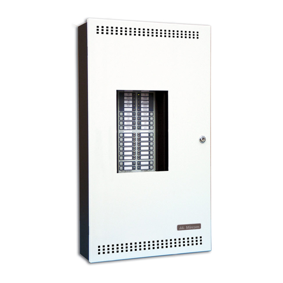
LED Fire Alarm Control Panel
Brand:
Mircom
| Category:
Control Panel
| Size: 1 MB
Table of Contents
Table of Contents
3
Industry Canada and FCC Notice
7
Introduction
8
Overall Features
8
Conventions
9
Circuits
9
Zone
9
Display Points
9
Wiring Styles
9
System Components
10
Main Fire Control Panel
10
Relay Modules: Six Relays
10
Polarity Reversal/City Tie
10
Remote Annunciator
11
Smart Relay Module
11
Input Class a Converter: Six Circuits
12
Output Class a Converter: Two Circuits
12
Active End-Of-Line
12
RAM-216 Remote Annunciator
12
Additional Fire Alarm System Accessories
12
Mechanical Installation
13
Installing the Enclosure
13
Figure 1: Box Dimensions, Surface Mount
13
Installing the Adder Modules
14
Figure 2: Installation of Adder Modules
14
Cable and Jumper Connections for Main Board and Adder Modules
15
Main Fire Alarm Board
15
Figure 3: Main Fire Alarm Board Cable Connector and Jumper Settings
15
ICAC-306 Input Class-A Converter Adder Module
16
Table 1: Connectors and Jumpers on the Main Fire Alarm Board
16
Figure 4: Icac-306 Input Class-A Converter Adder Module
16
OCAC-302 Output Class-A Converter Adder Module
17
Figure 5: Ocac-302 Output Class-A Converter Adder Module
17
RM-306 Six Relay Adder Module
17
Figure 6: Rm-306 Six Relay Adder Module
17
Figure 7: Rm-306 Relay Programming
18
Polarity Reversal and City Tie Module (Model PR-300)
18
Figure 8: Polarity Reversal and City Tie Module
18
Table 2: Pr-300 Jumper Settings
18
Field Wiring
19
Main Fire Alarm Board Field Wiring
19
Figure 9: Initiating Circuit – Class B or Style B Wiring
19
Figure 10: Initiating Circuit– Class a or Style D Wiring
20
Figure 11: Indicating Circuit – Class B or Style y Wiring
20
Figure 13: Four-Wire Smoke Detector Wiring
21
Figure 12: Indicating Circuit –Class a or Style Z Wiring
21
Relay Adder Module Wiring
22
Figure 14: Dialer Wiring
22
Figure 15: Relay Per Zone (Rm-306) Terminal Connection
22
Polarity Reversal and City Tie Module (PR-300) Wiring
23
Figure 16: Polarity Reversal and City Tie Module Terminal Connection
23
Power Supply Connection
24
Figure 17: Power Supply Connection
24
Wiring Tables and Information
25
Table 3: Initiating Circuit Wiring
25
Table 4: Indicating Circuit Wiring
25
Four-Wire Smoke Power (Regulated)
25
Supervised Auxiliary Power (Regulated)
25
Auxiliary Power (Unfiltered)
25
System Checkout
26
Before Turning the Power "ON
26
Power-Up Procedure
26
Troubleshooting
26
Indicators, Controls and Operations
27
Figure 18: Led Indicators and Control Buttons
27
Common Indicators
28
Alarm Circuit Indicators
29
Supervisory Circuit Indicators
29
Monitor Circuit Indicators
30
Trouble-Only Circuit Indicators
30
Signal Circuit Indicators
30
Common Controls
31
Circuit (Zone) Disconnect Buttons
32
Common Relays
32
Circuit Types
33
Evacuation Codes
34
Single Stage Operation
35
Figure 19: Evacuation and Alert Codes
35
Supported Protocols/Devices
36
Synchronous Strobes
36
System Sensor's I3 Devices
36
Configuration and CFG-300 LCD Service Tool
38
Figure 20: Fa-300 Configuration
38
Entering the Passcode
39
Command Menu
39
How to Use the Keypad to Program the FA-300
40
PANEL CONFIG (Command-Menu)
40
Default Configuration
48
Config Info
49
Set Time (Command-Menu)
50
Set Password (Command-Menu)
51
View Event Log (Command-Menu)
51
Clear Event Log (Command-Menu)
52
Walk Test (Command-Menu)
53
I3 Loop Test (Command-Menu)
54
Dialer Config (Command-Menu)
55
Test Dialer (Command-Menu)
60
Exit (Command-Menu)
62
CFG-300 LCD Service Tool Operation
62
Battery Trouble
63
Appendix A: Compatible Receivers
66
Appendix B: Reporting
67
Ademco Contact-ID
67
Security Industries Association SIA-DCS
68
Appendix C: Specifications
69
Appendix D: Power Supply and Battery Calculations (Selection Guide)
70
Warranty & Warning Information
71
Warning Please Read Carefully
71
Limited Warranty
73
Warranty Procedure
73
Disclaimer of Warranties
73
Out of Warranty Repairs
74
Advertisement
Advertisement
Related Products
MirCom FA-300 Series
Mircom FA-300-6LDR
Mircom FA-300-6LDW
Mircom FA-300-6DR
Mircom FA-300-6DDR-CG
Mircom FA-301-8LDW
Mircom FA-1000 SERIES
Mircom FA-101U
Mircom FA-1008KA
Mircom FA-204E
Mircom Categories
Control Panel
Intercom System
Fire Alarms
Smoke Alarm
Security System
More Mircom Manuals
Login
Sign In
OR
Sign in with Facebook
Sign in with Google
Upload manual
Upload from disk
Upload from URL