Table of Contents
Advertisement
Quick Links
Freescale Semiconductor, Inc.
User's Guide
Freedom KE06 User's Guide
1
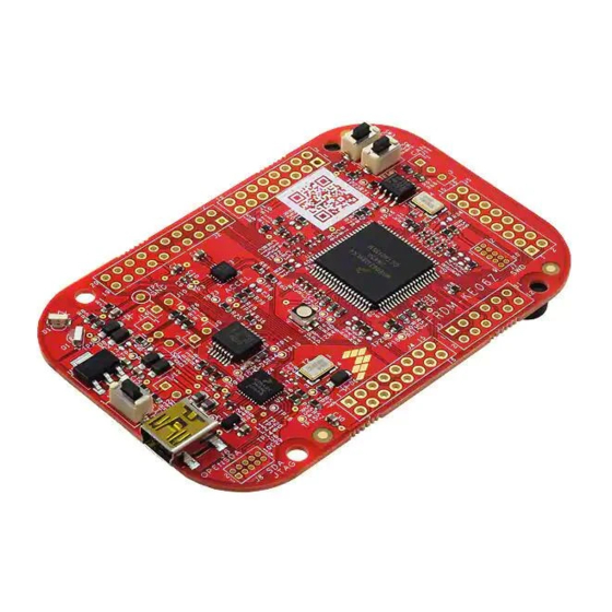
FRDM-KE06 hardware
overview
The FRDM-KE06 Freedom development platform
microcontroller board is assembled with the following
features:
•
Kinetis E series KE06 MCU in an 80-pin LQFP
package
•
On-board serial and debug adapter (OpenSDA)
•
I/O headers for easy access to MCU I/O pins
•
Freescale inertial sensor, MMA8451Q
•
Reset push button
•
RGB LED
•
Infrared communication
•
One thermistor
•
Motor control function for simple BLDC motor
control on APMOTOR56F8000E
•
CAN communication
Figure 1
shows a block diagram of the FRDM-KE06 board.
© 2014 Freescale Semiconductor, Inc.
Document Number: FRDMKE06UG
Rev. 0, 03/2014
Contents
1. FRDM-KE06 hardware overview . . . . . . 1
2. FRDM-KE06 hardware description . . . . . 2
2.1. Power supply . . . . . . . . . . . . . . . . . . 2
3.1. Debugging interface . . . . . . . . . . . . . 5
3.2. Virtual serial port . . . . . . . . . . . . . . . 6
3.3. KE06 microcontroller . . . . . . . . . . . . 6
3.4. Thermistor . . . . . . . . . . . . . . . . . . . . 7
3.5. Infrared port . . . . . . . . . . . . . . . . . . . 8
3.6. Key buttons . . . . . . . . . . . . . . . . . . . . 8
3.7. Three-axis accelerometer . . . . . . . . . 9
3.8. RGB LED . . . . . . . . . . . . . . . . . . . . 10
3.9. CAN . . . . . . . . . . . . . . . . . . . . . . . . 11
3.10. Input/Output headers . . . . . . . . . . 12
3.11. Arduino compatibility . . . . . . . . . . 13
Advertisement
Table of Contents

Related Manuals for Freescale Semiconductor FRDM-KE06


Summary of Contents for Freescale Semiconductor FRDM-KE06
-
Page 1: Table Of Contents
Freedom KE06 User’s Guide FRDM-KE06 hardware Contents 1. FRDM-KE06 hardware overview ..1 overview 2. FRDM-KE06 hardware description ..2 2.1. Power supply ....2 The FRDM-KE06 Freedom development platform 3. -
Page 2: Frdm-Ke06 Hardware Description
FRDM-KE06 hardware description Power supply The FRDM-KE06 offers a design with multiple power supply options. It can be powered from the USB connector, the V pin on the I/O header, an off-board 1.71-3.6V supply from the 3.3V pin on the I/O header or 3.3V from motor control board. - Page 3 FRDM-KE06 hardware description Figure 2. FRDM-KE06 power supply Table 1 provides the operational details and requirements for the power supplies. Table 1. Power supply requirements Regulated Supply source Valid range OpenSDA operational? on-board? OpenSDA USB (J6) Pin on I/O header 4.3-9V...
-
Page 4: Serial And Debug Adapter (Opensda)
Serial and Debug Adapter (OpenSDA) OpenSDA is an open-standard serial and debug adapter. It bridges serial and debug communications between a USB host and an embedded target processor as shown in Figure FRDMKE06UG, Freedom KE06 User’s Guide, Rev. 0, 03/2014 Freescale Semiconductor, Inc. -
Page 5: Debugging Interface
MCU connected to J7. When KE06 on FRDM board is 5V powered, and the OpenSDA is power off, there need to connect an external debugger to debug KE06 on board. FRDMKE06UG, Freedom KE06 User’s Guide, Rev. 0, 03/2014 Freescale Semiconductor, Inc. -
Page 6: Virtual Serial Port
The Kinetis KE06 microcontrollers feature an on-chip oscillator compatible with two ranges of input crystal or resonator frequencies: 32 kHz (low frequency mode), 4-20 MHz (high frequency mode). The KE06 on the FRDM-KE06 is clocked from an 8 MHz crystal. 3.3.2 Serial port The serial port interface signals used with OpenSDA are UART1 pin PTC7 (TXD1) and PTC6 (RXD1). -
Page 7: Thermistor
The sole debug interface on all Kinetis E Series devices is a Serial Wire Debug (SWD) port. The primary controller of this interface on the FRDM-KE06 is the onboard OpenSDA circuit. However, a 2x5-pin (0.05”) Cortex Debug connector, J7, provides access to the SWD signals for the KE06 MCU. The following table shows SWD connector signals description for KE06: Table 3. -
Page 8: Infrared Port
Two key buttons are connected to PTH3/4 to demonstrate KBI function of KE06, which can capture both falling edge and rising edge of key button input, as shown in the following figure. FRDMKE06UG, Freedom KE06 User’s Guide, Rev. 0, 03/2014 Freescale Semiconductor, Inc. -
Page 9: Three-Axis Accelerometer
GPIO signals as shown in the following table. By default, the I C address is 0x1D (SA0 pulled high). Table 4. Accelerometer signal connections KE06 MMA8451Q PTA3 PTA2 PTD4 INT1 PTD3 INT2 FRDMKE06UG, Freedom KE06 User’s Guide, Rev. 0, 03/2014 Freescale Semiconductor, Inc. -
Page 10: Rgb Led
Three PWM-capable pins are connected to a red, green, blue LED. The signal connections are shown in the table below. Table 5. RGB LED Signal Connections RGB LED KE06 Red Cathode PTG5/FTM2CH3 Green Cathode PTG6/FTM2CH4 Blue Cathode PTG7/FTM2CH5 FRDMKE06UG, Freedom KE06 User’s Guide, Rev. 0, 03/2014 Freescale Semiconductor, Inc. -
Page 11: Can
Serial and Debug Adapter (OpenSDA) Figure 9. RGB LED connection The CAN phy on KE06 FRDM board is 3.3 V powered. Table 6. CAN signal connection CAN Phy KE06 CAN_TX CAN_RX FRDMKE06UG, Freedom KE06 User’s Guide, Rev. 0, 03/2014 Freescale Semiconductor, Inc. -
Page 12: Input/Output Headers
I/O headers (J1, J2, J3, J4 and J5). J1 and J2 also function as motor control headers to provide access to a motor control board such as simple BLDC motor driving board APMOTOR56F8000E. FRDMKE06UG, Freedom KE06 User’s Guide, Rev. 0, 03/2014 Freescale Semiconductor, Inc. -
Page 13: Arduino Compatibility
3.11 Arduino compatibility The I/O headers on the FRDM-KE06 are arranged to allow compatibility with peripheral boards (known as shields) that connect to Arduino and Arduino-compatible microcontroller boards. The pins on the headers share the same mechanical spacing and placement as the I/O headers on the Arduino Uno Revision 3 board design. - Page 14 Semiconductor, Inc., Reg. U.S. Pat. & Tm. Off. All other product or service names are the property of their respective owners. ARM and Cortex are registered trademarks of ARM Limited (or its subsidiaries) in the EU and/or elsewhere. All rights reserved. © 2014 Freescale Semiconductor, Inc. Document Number: FRDMKE06UG Rev. 0...
Need help?
Do you have a question about the FRDM-KE06 and is the answer not in the manual?
Questions and answers